Note: Descriptions are shown in the official language in which they were submitted.
SU13STRATES FOR SUPPORTING ELECTRICAL TRACKS AND/OR COMPONENTS
This invention relates to substrates intended to support
electrical components, for example thick film resistive heating
elements, and it relates especially, though not exclusively, to
such substrates which comprise a metallic plate member coated on
one or both of its flat surfaces with a glass ceramic material.
The invention also provides a method of manufacturing such
substrates.
Such substrates are known, one being available under the
trade name KERALLOY from Wade Potteries plc, and have been
proposed for use in supporting resistive heating elements
applied, for example, as thick films by screen printing, and
intended for domestic usage, for example as hob heating elements.
Gs 9900~3 tAssociated Electrical Industries Limited), for
example, discloses a printed electrical heater assembly
comprising a metal backing membçr, a heat resistant electrically
insulating coating formed of e.g. a ceramic on at least one
surface of said metal and a conductive coating formed on said
insulating layer or layers of a material having a suitable
conductivity and pattern to form an electrical heater circuit or
circuits. The metal backing member having a heat resistant
electrically insulating coating on at least one surface provides
the substrate for the conductive coating.
DifficuIties arise in practice, however, with the use of
such subs~rates under the exacting operational conditions
associated with hob units. In particular, it has been found
~,
~2~7%3~
: 2
that electrical breakdown can occur b~tween the thick film
resistive heater and the metallic plate memb0r included in the
substrate, which is senerally held at earth potential, when
mains voltage is applied to the track. Fu{thermore, the thick
e;lm resistive heater track can exhibit lack of adhesion to the
glass ceramic material.
It has been determined by the inventor that both the
above-identified difficulties can be substantially reduced or
eliminated by ensuring that the percentage porosity of the glass
ceramic coating material, as deined hereinafter, is rendered
less than or equal to 2.5 and the invention provides a substrate
having a glass ceramic coating of such low porosity and a method
of producing such a substrate.
According to the present invention~ there is provided a
substrate for Rupporting electrical components, said substrate
comprising a plate member having on at least one surface a layer
of a glass ceramic material wherein the percentage porosity of
the glass ceramic layer, as defined hereinafter, is equal to or
less than 2.5.
By percentage porosity is meant the porosity at a random
cross-sectional plane through the Rubstrate perpendicular to the
plate member expressed as the percentage ratio of the
cross-sectional area of pores on the plane to the
cross~sectional area of the rem~inder of the gla~s ceramic layer
on that plane.
In order that the invention ~ay be clearly under~tood and
readily carried into effect, embodiments thereof will now be
described, by way of example only, with reference to the
accompanying drawings of which:
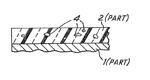
Figure 1 shows, in perspective view, a substrate in
accordance with one example of the invention.
Figure 2 shows a cross-sectional view, on a magnified
~cale, of the substrate shown in Figure 1, and illustrates how
the degree of poros$ty of the glass ceramic layer is specified,
and
Figures 3a and 3b show, in plan view, substrates of the
~25~%3~3
: 3
kind shown in Plgure 1, bearing a re~i~tive heating track
suitable for use on a hob unit.
Referring now to Figure 1, there is shown a substrate
including a support plate 1, made of e.g. metal or a glass
ceramic material oE suitable thickness to provide rigidity,
coated on either side with a glass ceramic material 2,3, such
as a calcium magnesium alumina silicate. The glass ceramic
coatings 2,3 are applied by screen printing powdered glass
ceramic material on to the support plate, or by
electrophoresis. It is a cbaracteristic of glass-ceramic
materials that they can be caused to crystallise by the
application of heat, and it is usual in this field for the
powdered coatings of amorphous glass to be caused to
crystallise, thus converting them into continuous glas~ ceramic
layers, by heating the entire ~ubstrate, in a single-stage
process, up to a temperature in excess of 1000 C, above the
materlal's softening point, at which it crystallises rapidly.
The material is then allowed to cool.
Substrates prepared in this way, however, tend to exhibit
an undesirably high degree of porosity, the percentage porosity
value being determined e.g. as ~hown in Figure 2 by making a
random cro~s-sectional cut through the substrate perpendicular
to the plane of the support plate. The ratio of the area of all
pores such as 4 sliced through by the cut to that of the
remainder of the glass ceramic layer in the plane of the cut i~
called the porosity ratio and is conveniently expressed a~ a
percentage (P). It is a characteristic of tnis invention that
the value of P is equal to or less than 2.5. This compares with
values of P of 4~0 or more achievable by more conventional
processing.
The desirably low values of P required by the invention are
achievable, the inventor has determined, by observing tha~ the
powdered glass ceramic coati~g can be converted into a
continuous layer by means of a two-stage heating process, in the
first stage of which the substrate i8 heated, not to the
aforementioned temperature in exce s of 1030 C, at which
3~3
~l
crystalllsation OCCUt8 rapidly, but rather to ~ te~perature
above the softening temperature of the glass c~ramic material,
but below th~ temperature at which rapid cry~tallisatlon occurs,
e.g. in the range of from 800 C to 890 C, prefe!rably in the
range of from 800 C to 875 C for the aforementioned calcium
magnesium alumina silicate, at which the material has softened
appreciably but crystallises only slowly, for a time dependent
upon the temperature concerned, but typically of the order of
five to thirty minutes. This time is dependent upon the rate of
crystallisation and the viscosity of the material in its
softened state~ At the lower end of this range, the viscosity
of the coating material is high, but crystallisation is 810w and
an extended time may be allowed for pores to close. At the
upper end of the range, the viscosity of the coating is markedly
reduced, and, although, crystallisation is relatively rapid, the
majority of pores are found to close before an appreciably
crystalline layer is formed. For the aforementioned calcium
magnesium alumina silicate, in the first stage of the pr~cess
the material is preferably heated at 875 C for 7 minutes. The
mechanism of pore closure is believed to be primarily that of
surface tension.
~ he second stage of the process, which involves the
rendering permanent of the glass ceramic sta~e by heat
treatment, ~imilar to that conYentionally u~ed, and as mentioned
above, is ~o raise the coating temperature to a value ~e.g~ in
e~cess of 1000 C for the aforementioned calcium cagnesium
alumina silicate) at which rapid crystallisation occurs, but
below that at ~hich the crystal~ redissolve, the rapid
crystallisation producing a glass ceramic layer. The end result
is the production of a substrate in which the glass ceramic
layers exhibit percentage porosities of 2.5 or less. This is
found to reduce con~iderably the incidence of failure o~ heater
units by electrical breakdown and alqo improves adhesion of the
thick film resistive heater track to the glass ceramic material.
In another method the substrate is produced by the
application of a plurality of glas~ ceramic layers to the
1~:723~3i3
support plate, each individual l~yer belng produced by the
two-stage heatlng pr~cess. ~he lnventor ha~ found tha~ the
electrical bre~kdown characteristics of the substra~e depend
markedly on and are improved by the number of glass ceramic
layers used, even if the overall thickne~s of the composite is
the same. The reason for this appears to be that pinboles may
be produced during the formation of a layer which are too large
to be completely closed during the first stage of the two stage
heating process, but that there is a ve~y small chance that
pinholes in successive layess will coincide to provide a
complete path trom the electrical component to the metallic
support plate.
It is also possible to produce the substrate by applying a
plurality of glass ceramic layers, each individual layer being
treated using the first stage of the heating process before the
next layer is applied. The composite layer may then be rendered
per~anent using the second stage of the two-stage heating
process. Substrates produced using this method do exhibit some
improvement in their electrical characteristics.
The use of screen printing to apply glass ceramic coatings
to produce the substrate is particularly applicable to the
methods as described in accordance ~ith the present in~ention.
To provide a glass reramic layer of ~ui~able thickness, e.g.
100 ~ m, four coatings of glass ceramic material are printed onto
th~ support plate, the whole then being fired using the
two-stage heating process. Alternatively, the two-stage heatiDg
firing is used to produce a first glass ceramic layer after two
coatings have been printed, following which a subsequent two
coatings are printed and fired by the two-stage heating
process. The resultiny glass ceramic layer produced in this
method is of the same thickness as that produced by the
aforementioned me~hod but has significantly improved electrical
breakdown characteristics.
In another method using screen printing, two coating~ are
printed and then Eired using the two-stage heating proceæs.
m is is repeated a ~urther two time~ to produce a gla~s ceramlc
~723~3
o 6
layer of greater thickness e.g. 150 ~ . The further slgnificant
improve~ent in electrical breakdown characterl~tics for the
glass ceramic layer produced by this method is believed to be
caused by the combination of multiple firings and the greater
s thickness of the glass ceramic layer.
In producing substrates using screen printing, it has been
found that, provided that the composite glass ceramic layer on
the substrate is of suitable thickness, two is the optimum
number of coatings to be prin~ed and then fired at the same time
using the two-stage heating process. The advantage of this may
be in the production of a glass ceramic layer of sufficient
thicknes~ whose state, including the position of any pinholes,
has been rendered permanent, before the next layer is applied.
It is possible that, if an individual glass ceramic layer,
applied and fired using the two-stage heating process, is not of
sufficient thickness, the benefit of using multiple firings is
lessened.
Figures 3a and 3b show typical thick film tesistive heating
tracks 10 and 20 printed in known manner on to the coated
surface 2 of a substrate of the kind shown in Figure lo The
track can be of precious metal or any other suitable mat~rial
kno~n to those in the art and the entire unit as shown in
Figures 3a or 3b is preferably overglazed with glass ceramic
material.
In use, a unit such as that shown in Pigures 3a or 3b, or a
larger substrate containingl say, four individually energisable
heating tracks may be deployed either beneath a conventional
glass cPramic hob top to provide the heater units o~ a domestic
hob or cooker, or as a hob unit itself. ~eater units so
provided have low thermal mass, and correspondingly a thermal
response which is considerably faster than that o~ conventional
cooker elements and can approach that of the recently developed
technology which utilises halogenated tungsten filament lamps as
heat source~.
Clearly, the inventlon's u~e is not restricted to hobs and
cookers~ qhere are many domesti~ and industrial heati~g
23~
: 7
applications for which the invention would be suitable. Some
non-llmitative exampleR are ,;ettle ~U99, electric irons, space
heaters, tumble dryers, and ovens.
It will be appreciated that the heater units need not be
formed as, or retained in the form of, a flat plate and other
substrate configurations, such as cylinders and cones, can be
used for certain applications if desired. Air can be forced
over and/or through a suitably shaped heater unit, if desi}ed,
to distribute heated air to locations other than the im~ediate
vicinity of the heater unit itself.
The invention can also be used in low-power applications,
where for example, resistive components desposited on a
substrate need to be laser trimmed to a predetermined value of
resistance. The low porosity exhibited by the glass ceramic on
a substrate in accordance with the invention is beneficial
because it reduces the incidence of uncontrolled rupture of a
component beiny trimmed by a laser beam which can occur if the
beam punctures a pore in the vicinity of the component. Such
rupture usually causes the resistance value of the component to
depart from tolerance and thus necessitates the scrapping, or at
least reprocessing, of the unit.