Note: Descriptions are shown in the official language in which they were submitted.
~88~Z
DOL 081 PA -1-
PORTA~3LE AD~USTABLE CHILD'S ~HAIR
Backqround of the Invention
This invention relates to a portable adjustable
child~s chair having a means for adjusting seat panel
elevation and back panel depth to form a chair of desired
height and depth. It also relates to a portable adjustable
child~s chair which is convertible into a booster seat or
high chair.
Booster seats are well known as a means of
seating children in conventional chairs at tables of
various height. While individual booster seats have been
manufactured in different sizes to accommodate smaller or
larger children, none adapt to accommodate children as
they grow in size.
Combination chair assemblies are also well known.
wherein a chair, in combination with various support
structures, serves a plurality of purposes, including use
as a high chair. For example, U.S. Patent No. 2,530,474
shows a chair assembly functioning as a rocking chair,
swing, high chair with removable tray, or straight chair.
The chair seat, removable to allow the straight chair
configuration to function as a nursery toilet, performs no
adjustment function. U.S. Patent No. 3, 078,101 shows a
chair that may also serve as a high chair, stroller, and
lounge chair. Again. this chair seat, while removable,
performs no adjustment function. The back panel, however,
does recline by means of a hinge and support. While
versatile, the '474 and '101 patents do not teach the
removal or adjustment of seat or back panels as a means to
adjust the height and depth of chair size.
However, chair arrangements are known having
means for adjusting seat panel elevation to adapt to
128~
DOL 081 PA -2-
growing children. U.S. Patent No. 3,575,465 shows a
modular construction adaptable for a multitude of
fu~niture purposes including chairs, shelves, bookcases,
beds, clothes racks, tables, and dividers. The '465
patent includes as a feature the use of a plurality of
spaced grooves or channels which slidably receive and
maintain planar accessory elements to permit variation of
seat level when the modular construction is used as a
chair. So used, the back is rigid and not susceptible of
any adjustment.
U.S. Patent No. ~,109,961 shows an adjustable
chair having a plurality of horizontal grooves or channels
on uprights which permit the variation of seat level of
the chair. The '961 patent teaches the use of a second
plate, interchangeable with the seat panel, to serve as a
footrest and support which enables children of any age and
size to use ~he chair. The chair stands on its own and
accommodates, by varying the seat and footrest height, ~he
seating of its occupant at standard tables. This
invention also includes a seat belt for use by young
children, but no tray. The uprights shown in the '961
patent are connected at three points: at their lower ends
by a cross piece, at their middle by a cross bar, and most
notably at the upper end by a back rest plate. Screw nuts
at these connections provide, when tightened, the pressure
necessary to retain the seat and footrest plates.
Accordingly, in all instances, the back rest plate remains
fixed.
Additionally, the use of removable trays, seat
belts, and straps for securing seats to supports in
combination with children's chairs are known in the prior
art. Removable trays are shown by U.S. Patent Nos. Des.
148,380: Des. 152,383; Des. 157,959: 2,530,470; 3,078,101;
~8~30~2
DOL 081 PA -3-
3,335,434; Des. 246,642: and 4,453,764. Seat belts are
shown by U.S. Patent Nos. 3,335,434 and 4,109,961, and
fabric straps for attachment to an existing base are shown
by Patent No. 3,335,434.
As can be seen the prior art reveals a long-time
concern with versatility of ~unction in children's
furniture. But, a drawback has been the need to transport
support bases with seats outside the home and a lack of
suitability for children of different sizes. More
recently, the focus has been on the adjustability of
children's chairs. However, known chairs, while somewhat
adjustable, still lack portability and, as complete pieces
of furniture, may be aesthetically incompatible with
existing furniture.
Accordingly, there remains a need for portable,
adjustable, combination child's chair, booster seat and
high chair which may be used with existing furniture and
which may be easily stored when not in use.
SummarY of the Invention
The portable, adjustable combination child's
chair, booster seat and high chair of the present
invention features side panels having a series of
generally horizontal and vertical grooves or channels on
their inner surfaces into which separate back and seat
panels may be variously inserted to form a chair of
desired height and depth. The side panels are separated
and supported by means which, in combination with the side
panels, form a stable rigid frame. The overall structure
3~ therefore permits the child's chair to be easily adjusted
to accommodate growing children. Its size makes it
readily portable and easily stored.
Additionally, means for retaining the occupant in
the chair, such as an adjustable seatbelt, may be used.
~288~
DOL 081 PA -4-
Further, means for securing the child's chair to an
existing chair or support, such as adjustable straps, may
be used to convert the chair to a booster seat. Finally,
a serving tray may be removably attached to the side
panels for the use by the occupant.
So used, the portable adjustable child's chair may
function as a play chair, and when secured to an existin~
chair or suppoet, function as a high chair.
DesceiPtion of the Deawinas
Figure 1 is a peespective view of the child's
chaie of the present invention showing the seat panel low
and back panel rearward.
Figure 2 is a peespective view of the child's
chair of Fig. 1 incoepoeating the teay and showing the
seat panel elevated and back panel foewaed.
Figure 3 is an exploded perspective of the
child~s chaie of the peesent invention showing the
eelationship of the vaeious panels and structure.
Figure 4 is a cross-sectional view taken along
line 4 - 4 of Fig. 2 showing means of supporting the side
panels and attachment theeeto.
Figuee 5 is a ceoss-sectional view taken along
line 5-5 of Fig. 2 showing the side panel notch and teay
2s latch.
DescriPtion of the Peefereed Embodiments
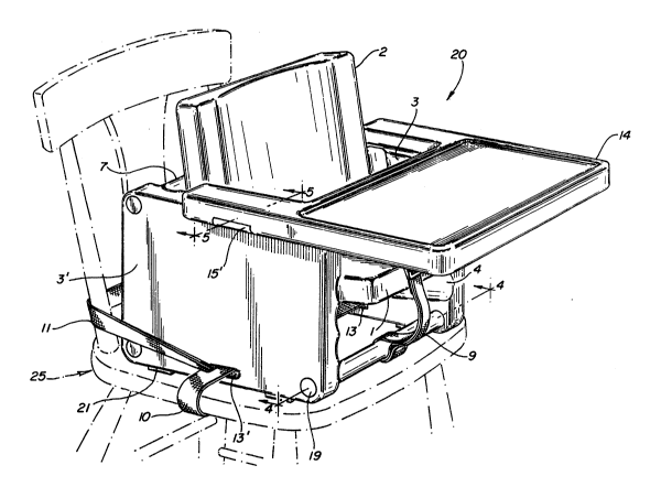
Refeering to the drawings, Figuees 1 and 2 show
the portable, adjustable child's chair, generally
indicated at 20. Figures 1 and 2 comprise separate
embodiments of the present invention. While shown
functioning in Figures 1 and 2 as a booster chair and high
2S8032
DOL 081 PA -S-
chair, respectively, the child's chair 20 may be also used
separately on the floor as a play chair, with or without
tray 14, ideal for meals, crafts, or watching television.
Briefly, referring to Figures 1 and 3, child~s
chair 20 includes two side panels 3, 3' which in
combination with tubular supports 7 and tie rods 8 form a
frame into which a seat panel 1 and a back panel 2 may be
slidably inserted.
The side panels 3 and 3' each have a plurality of
generally hoeizontal grooves or channels 4 and generally
vertical grooves or channels 5 for adjusting the height
and depth of the seat panel 1 and back panel 2
respectively. It should be noted that the grooves 4 and 5
can be varied in angle from precise horizontal and
vertical orientation, preferably being angularly displaced
to recline somewhat the seat panel 1 and back panel 2
panels as shown in Figures 1-3. Further, while the
preferred embodiment shows only three horizontal grooves 4
and three vertical grooves 5, the number of grooves or
channels may be varied to provide greater or lesser
adjustability.
To enhance the portability of the child~s chair
ZO, the side panels 3, 3', seat panel 1, and back panel 2,
are made of lightweight material, such as plastic,
blow-molded in a manner generally known in the art.
Similarly, the three tubular supports 7 are lightweight,
made of commercially available plastic tube, molded or
extruded in a manner generally known in the art.
The tubular supports 7 and tie rods 8 work in
combination to separate and support the side panels 3, 3~
to form a stable rigid frame. Referring to Figures 3 and
4 the tie rod 8, made of commercially available metal
288~32
DOL 081 PA -6-
pipe or rod, preferably steel,has a circumferential bead
at one end and is threaded at the other. So made, tie rod
8 may be fitted with a washer 17 at the beaded end and the
threaded end passed first through one side panel, through
tubular support 7 through the second side panel, and
finally fitted with washer 17, and screw nut 18.
Screw nuts 18, when tighted, compress the tubular
supports 7 separating the side panels 3, 3', and thereby
form a stable rigid frame. The openings on the outer
surfaces of side panels 3 and 3' are then covered by
molded plastic caps 19.
The seat panel 1 and back panel 2 are contoured
as illustrated by numeral 6 for the comfort and safety of
the occupant. The contour 6 aids in retaining the
occupant in the child~s chair 20 by friction which is
further enhanced when the seat panel 1 is slightly
reclined.
The ~emaining elements of the invention, soft
rubber feet 21, a seat belt 9, chair straps 10 and 11, and
a serving tray 14 are optional, although desirable and
preferred in practicing the invention. Commercially
available, four soft rubber feet 21, two each attached to
the bottom edges of side panels 3, 3', add stability and
skid-resistan~e to child's chair 20 and protect existing
chairs 25 or supports, as shown in Figures 1 and 2. A
seat belt 9 for retaining the occupant in the child's
chair 20 is shown in Figures 1-3. Commercially available
fabric seat belts 9 having adjustable interlocking ends 12
and 12' may be used. As shown in Figures 1 and 3, two
segments of the seat belt 9 may be passed between seat
panel 1 and back panel 2 and looped around rear tubular
support 7 to provide waist restraint, while the third
segment is looped around front tubular support 7 to
~ \
~2~8032
DOL 081 PA -7-
provide crotch restraint for the occupant. Preferably, the
seat belt loops are sewn and looped around tubular
supports 7 during assembly.
Referring to Figure 1, fabric chair straps 10 and
11 are threaded side-to-side through slots 13 and 13'
centrally located along the bottom edge of each of side
panels 3 and 3'. Chair straps 10 and 11 are then passed
under and around an existing chair 25 or other support to
secure the child~s chair 20 onto ~he existing chair 25
where it functions as a booster seat. Such fabric straps
are commercially available and have interlocking ends 12
and 12' as shown in Fig. 3. Such interlocking ends 12
and 12' also preferably have means for adjusting the
length of the strap. Alternatively, the either chair
strap 10 or 11 could be threaded front to back by removing
the strap from slots 13 and 13', passing the strap below
the seat panel 1, looping the strap around each of the two
bottom support tubes 7, and thence under the existing
chair 25. In either case, the chair straps 10 and 11 are
adjusted to secure the booster seat snugly to an existing
chair 25 or support.
With reference to Figure 2, a serving tray 14 is
attached to and supported by the top edges of the side
panels 3 and 3'. In this embodiment the child's chair 20
is converted into a high chair. Latches 15 and 15' on
each arm of the tray 14 snap into notches 16 and 16' near
the top outer edge of each side panel as shown in Figure
5. The bottom surfaces of the tray arms are indented to
conform to the top edge of the side panels upon which the
tray rests to add stability to the assembly. Fi~ure 3
shows a single notch 16 and 16' in each side panel,
preferable to afford both stability to the tray 14 and a
``` " 1288032
DOL 081 PA -8-
fu:Ll eange of seat adjustment. Multiple sets of notches,
to permit adjustment of tray location, are also possible.
The tray 14 is made of blow-molded plastic, and its light
weight enhances its portability, use, and storage.
Having described the invention in detail, what is
claimed is: