Note: Descriptions are shown in the official language in which they were submitted.
-1- 1~5?1~7'7
CHOKE AND IMPROVED NEEDLE TIP THEREFOR
Background
Chokes are used in flow lines to create a restriction
in the flow. In many applications of chokes, the high
05 velocity flow or the entrained moisture or particles are
particularly damaging to the tip of the choke valve
member. In such applications, the tip is made of an
erosion resistant material, such as tungsten carbide.
Rather than make the whole of the needle or valve member
out of the erosion resistant material, the tips are made
to be replaced.
Prior to the present invention, such tips have been
silver brazed onto the needle stem. Few are qualified to
perform this silver brazing so that it is difficult to
replace a tip and have it properly installed.
Threading of the tungsten carbide tip would be
advantageous except that forming threads in tungsten
carbide is an expensive operation.
U. S. Patent No. 852,644 discloses a refractory
stopper which includes internal threads and a nut embedded
in the stopper through which the threads extend so that
the stopper can be threaded onto the stem.
U. S. Patent No. 1,499,433 discloses a throttle valve
in which the tip is attached to the stem with a ring
positioned in a groove in the stem and a plug threaded
into the tip and engaging the ring to thereby secure the
tip to the stem.
U. S. Patent No. 1,831,713 discloses a choke or
adjustable flow bean in which the tip is threaded onto the
stem into abutment with disc which is secured to the stem
with a set screw being used to prevent the unthreading of
the tip from the head.
U. S. Patent No. 1,911,905 discloses a choke or
adjustable flow bean in which the tip is secured to the
77
--2--
stem by a pin extending through the stem and through the
outer portion of the tip which surrounds the stem and
through the stem.
05 U. S. Patent No. 3,262,673 discloses another stopper
structure which includes a split sleeve positioned in a
stem groove and having external threads which are adapted
to engage within internal threads in the stem opening in
the stopper.
U. S. Patent No. 3,693,732 discloses a well control
choke in which the stem is surrounded by a sleeve which
receives a plug in an enlarged recess in its outer end
which extends beyond the end of the stem and is held in
position by the threading of the plug onto the end of the
stem.
U. S. Patent No. 3,761,053 discloses a needle valve
in which the needle is replaceable and is provided with a
spherical end which is received within a slot in the stem
or is secured by a collar retaining it against the end of
the stem.
U. S. Patent No. 4,337,920 discloses another method
of securing a wear-resistant, sleeve-type valve member to
its stem in a choke which is subject to high temperatures
and extreme erosion conditions. This includes the utili-
zation of annular springs positioned around the stem andwithin the wear-resistant sleeve.
Summary
The present invention relates to an improved choke
with an improved wear resistant tip which is easily and
quickly fastened to the choke stem. The improved choke
includes a body with an internal valve chamber, an inlet
and an outlet communicating through the body into the
valve chamber, a valve seat surrounding the opening of the
outlet into the valve chamber, and a valve member mounted
within said body to move toward and away from said valve
seat to control flow therethrough, means for moving the
valve member in said body, the valve member having a stem
and a replaceable, wear-resistant tip which is provided with a
sleeve insert secured within the stem opening and having internal
threads which mate with external threads on the end of the stem,
the tip recess includes a groove into which a portion of the
sleeve insert is swaged to secure it tightly into the tip.
In one aspect, the invention provides a choke comprising
a body having an internal valve chamber with an inlet and an
outlet communicating through the body into the valve chamber, a
seat positioned within said valve chamber surrounding the opening
of the outlet into the valve chamber, a valve member positioned
within said valve chamber and including a stem and a wear-
resistant tip, means connected to said stem to move said stem and
said tip toward and away from said seat to control flow
therethrough, said stem being threaded on its end for fastening to
said tip, said tip having an internal cylindrical recess with an
annular groove in the surface of said recess, a sleeve insert
having internal threads mating with the threads on the stem and
having a shank portion swaged into the groove in said recess to
secure said sleeve insert within said recess.
In a further aspect, the invention provides a
replaceable choke tip comprising a tip body having an exterior
surface adapted to coact to control flow through a choke, a bore
into the end of the tip body opposite to said exterior surface and
a groove in said bore space inwardly from said surface, and a
sleeve inserted into said bore and having internal threads and
having a portion of its exterior swaged into said groove to secure
said sleeve within said bore.
The present invention offers the advantage of providing
A
~ f 7
3a
an improved choke in which a wGrn, wear-resistant valve member tip
is easily and quickly replaceable.
A further advantage is the provision of an improved
choke in which a worn valve member tip of wear-resistant material
may be replaced with another wear-resistant valve member tip which
has a relatively inexpensive and simple means
for securing it to the valve stem.
Still another advantage of the invention is the
provision of an improved replaceable, wear-resistant tip for a
choke which is readily removed and replaced and has a reliable and
inexpensive means for securing it to the end of the valve stem.
Brief DescriDtion of the Drawinas
These and other objects and advantages are hereinafter
set forth and explained with respect to the drawings wherein:
FIGURE 1 is a sectional view of the improved choke of
the present invention.
FlGURE 2 is a sectional view of the improved replaceable
wear-resistant tip of the present invention.
FIGURE 3 is a sectional view of the improved tip with
its sleeve insert secured therein.
FIGURE 4 is a sectional view of the improved tip secured
onto the threaded end of the stem.
DescriDtion of the Preferred Embodiments
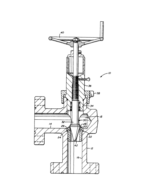
Improved choke 10 of the present invention is
illustrated in FIGURE 1 and includes body 12 with inlet 14 and
--4--
outlet 16 communicating through body 12 into interior
valve chamber 18. Valve seat 20 is positioned within
valve chamber 18 in position surrounding the opening of
outlet 16 into valve chamber 18. Valve seat 20 is suit-
ably secured as by threading within outlet 16 and includes
flange 22 which engages surface 24 of counterbore 26 in
the opening of outlet 16 into valve chamber 18 and wear-
resistant seat insert 28.
Valve member 30 includes stem 32 extending through
opening 34 in body 12 and through sleeve 36 which is
secured therein by clamp ring 38. The portion of stem 32
within sleeve 36 is threaded into the threads on the
interior of sleeve 36 and is moved by handwheel 40 rotat-
ing stem 32 and because of its threaded engagement withinsleeve 36 causes valve member 30 to move toward and away
from valve seat 20 to control flow therethrough. Tip 42
is secured to the inner end of valve member 30.
Tip 42 is a wear-resistant replaceable unit and, as
shown in FIGURE 2, includes body 44 which has a tapered
conical surface 46 to coact with valve seat insert 28. A
suitable material for tip 42 is tungsten carbide. A means
is provided for securing tip 42 onto the threaded end of
stem 32. Such securing means includes sleeve 48 which has
outer flange 50, shank portion 52 and internal threads 54.
Tip body 44 includes bore 56 in its end opposite surface
46 with counterbore 58 to provide surface 60 surrounding
kore 56. Groove 62 is provided in the interior of bore
56. Sleeve 48 is positioned within bore 56 with flange 50
in engagement with surface 60. Shank portion 52 is swaged
into groove 62 to secure sleeve 48 in its position as
shown in FIGURE 3.
Such securing means provides the securing of tip 42
on stem 32 by threading threaded pin 64 of stem 32 into
sleeve threads 54. The end of stem 32 includes radial
flange 66 providing annular surface 68 surrounding reduced
portion 70 of stem 32 which fits into counterbore 58 as
shown in FIGURE 4. Pin 64 which extends beyond portion 70
.~..4`}1~77
is threaded into threads 54 of sleeve 48. Assembly of tip
body 44 onto stem 32 is complete when flange surface 68 of
stem 32 engages end surface 72 of tip body 44. In this
05 position shoulder 74 between pin 64 and reduced portion 70
is positioned a slight distance from engagement with
flange 50 of sleeve 48.
It is preferred that sleeve 48 be a product as
described above and as provided by the B. F. Goodrich
Company under the trademark "Rivut." The material of
sleeve 48 should be selected to withstand the conditions
to be encountered within choke 10. Generally, the materi-
al of sleeve 48 would preferably be stainless steel.
With the improved tip of the present invention,
sleeve 48 can be assembled within tip body 44 at the
factory and shipped to a customer's location for use as a
replacement of a worn or damaged tip at the point of usage
so that it is only necessary to shut down the system and
bleed the pressure from choke 10 to disassemble the
components and replace the used tip body with a new tip
body. No silver brazing or complex assembly is required
for this replacement. Also, the improved tip is relative-
ly simple to construct and does not involve the expensive
process of having to form internal threads within the
tungsten carbide tip.