Note: Descriptions are shown in the official language in which they were submitted.
~2~7S4!~
FERRORESONANT TRANSFORMER WITH DUAL OUTPUTS
1 BACKGROUND OF THE INVENTION
2Thls invention relates to ferroresonant
3transformers such as those used in power regulation,
4and especially to the use of such ferroresonant trans-
5formers as self-regulating power control devices.
6More particularly, the invention relates to the use of
7ferroresonant transformers in systems where more than
8one load is to be powered, and where the loads are
9preferably electrically and magnetically isolated from
10one another.
11Ferroresonant transformers have been used in
12many applications, including voltage regulating sys-
13tems, for several decades. They comprise basically a
14laminated steel core around which are wound separate
15primary and secondary windings, with steel shunts
16placed between the primary and secondary windings.
17These magnetic shunts between the primary and secon-
18dary windings create an inductive coupling between the
19primary and secondary circuits. Integral with the
20secondary winding ls a resonant winding coupled to a
21capacitor, sometimes called a "ferrocapacitor. n The
22capacitor, or ferroresonating capacitor, shunts the
23saturating lnductor or winding, and is usually near
24resonance with the linear inductance.
25The comblnatlon of the resonant capacitor
26and the inductive coupling produced by the shunts
27creates a resonant circuit. The gain of this resonant
~Z~75~
1 clrcuit drives the magnetic flux in a portion of the
2 core within the secondary winding to saturation. That
3 is to say, this portion of the core cannot be driven
4 to a higher flux density despite changes in the input
S voltage or output load. Since voltage induced ln the
6 secondary winding ls proportlonal to flux density, the
7 voltage at the terminals of the secondary winding (the
8 load voltage) remains constant.
9 The ferroresonant transformer thus functions
to provide a constant output voltage despite changes
11 in output load or input voltage. In addition, the
12 saturation of the secondary sectlon of the core causes
13 the output waveform to be nearly a square wave rather
14 than a sine wave. Thls i5 advantageous where the
output is rectifled and flltered ln order to provlde a
16 D.C. power supply.
17 An additlonal advantage of the ferroresonant
18 transformer is that the inductive coupling of the
19 primary and secondary clrcults makes the transformer
lnherently current-llmlted. If the secondary ls
21 shorted, the prlmary current ls limited to safe levels
22 because there 18, ln effect, a substantlal lnductance
23 between the prlmary and secondary circuits.
24 There are numerous appllcations for ferro-
resonant transformers where multiple loads are to be
26 powered, and lt is desired to provlde redundancy such
27 that the short clrcult of one load wlll not affect the
28 others. This is conventionally accomplished by using
29 multiple transformers.
An example of this is in cable televlsion
31 applicatlons, where ferroresonant power supplles are
~2975~6
1 used to provide 60 volts A.C. on the distribution
2 cable to drive amplifiers and other components. It is
3 desirable to isolate sections of cable from one
4 another so that a fault on one sectlon whlch ~horts
the cable will not affect adjolning sections of the
6 cable.
7 The solution, as indicated above, has been
8 to use two or more ferroresonant transformers to
9 achieve the desired electrical and magnetic isolation
between the different sections. This ls a cumbersome
11 and costly arrangement, and is particularly undesir-
12 able where weight constralnts are in the picture.
13 The device of the present invention reduces
14 the difficulties indicated above, and affords other
features and advantages heretofore not obtainable.
16 SUMMARY OF THE INVENTION
-
17 It is among the ob~ects of the present
18 invention to provide a ferroresonant transformer with
19 two outputs that are electrically and magnetically
isolated from each other.
21 Another object is to provide a ferroresonant
22 transformer with multiple outputs wherein a short
23 clrcuit across the terminal of one output will have no
24 effect on any other output.
The above objects and advantages are
26 achieved with the ferroresonant transformer design of
27 the present invention wherein, as conventional
- 12~7546
1 components, there are a ferromagnetlc core and a
2 primary windlng on the core adapted to be connected to
3 a source of alternatlng current. In accordance wlth
4 the inventlon, there is a first secondary wlnding
section on the core coupled to a first load and a
6 first magnetic shunt means disposed between the pri-
7 mary wlndlng and the flrst secondary windlng section.
8 A flrst resonant winding connected to a ferrocapacltor
9 is coupled to the flrst secondary windlng. There is
also provided a secondary winding section on the core
11 coupled to a second load independent of the first
12 load. A second magnetlc shunt means is disposed
13 between the primary winding and the second secondary
14 windinq section, and a second resonant windlng con-
nected to a ferrocapacitor is coupled to the second
16 secondary winding section. Accordingly, the flrst
17 load ls electrlcally and magnetically isolated from
18 the second load, and a short circult across elther
19 load will have no effect on the other load.
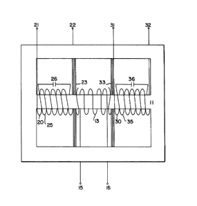
21 BRIEF DESCRIPTION OF THE DRAWINGS
22 The figure in the drawings ls a clrcult
23 dlagram lllustrating a typical ferroresonant trans-
24 former design embodying the present invention.
129754~i
1 DESCRIPTION OF THE PREFERRED EMBODIMENT
2 Referrlng to FIG, 1 there ls shown a ferro-
3 resonant transformer wlth dual outputs electrlcally
4 and magnetlcally isolated from one another, The
transformer includes a ferromagnetic core 11 of con-
6 ventional design and a prlmary wlnding 13 with input
7 termlnals 15 and 16. The transformer al~o includes a
8 first secondary winding 20 and a second secondary
9 winding 30, the windings 20 and 30 being located at
opposite axial ends of the primary windlng 13, The
11 . first secondary winding 20 has output termlnals 21 and
12 22, and is lnductively coupled to the primary windlng
13 13 by a magnetic shunt 23.
14 The second secondary wlnding 30 has a pair
of output terminals 31 and 32, and is inductively
16 coupled to the primar,y winding 13 through a magnetic
17 shunt 33.
18 The shunts 23 and 33 form a highly reactant
19 shunt between the primary portion of the transformer
and the respective secondary winding, whereby the
21 magnetic fluxes generated by the primary and each
22 secondary winding may link themselves to the exclusion
23 of the other windlng, thereby making the itran~former
24 one of a high reactance type.
Associated with the first secondary winding
26 ' 20 is a first resonant wlnding 25 connected to a first
27 ferrocapacitor 26.
28 Likewise, the second secondary winding 30
29 has a second resonant winding 35 associated therewith
connected to a second ferrocapacitor 36.
- 129754~
1 Operation
2 In accordance with the standard operation of
3 a ferroresonant transformer, when an input voltage ls
4 applied across the terminals 15 and 16, the result is
that the magnetic ~hunts 23 and 33 between the primary
6 winding and secondary wlndings 20 and 30 slmultan-
7 eously create an inductlve coupllng between the prl-
8 mary wlnding 13 and the first secondary windlng 20 and
9 between the primary winding 13 and the second secon-
dary wlnding 30. The first and second resonant wlnd-
11 lngs 25 and 35, ln comblnation with the respectlve
12 resonant capacitors 26 and 36, create respectlve
13 resonant clrcults. The galn of the respectlve reso-
14 nant circults drlves the magnetic flux in the portion
of the core within the respectlve secondary winding to
16 saturation. That is, this portion of the core cannot
17 be driven to a higher flux density despite changes ln
18 lnput voltage or output load. Because the voltages
19 induced in the secondary windlngs 20 and 30 are pro-
portlonal to the flux denslty ln the core, the volt-
21 ages at the termlnals of the secondary wlndlngs 20 and
22 30 remain constant. The ferroresonant transformer
23 thus functlons to provide a constant output voltage
24 desplte changes ln output load or lnput voltage. In
addltlon, the saturation of the secondary sectlons of
26 the core causes the respective output waveforms to be
27 nearly a square wave rather than a slne wave. This is
28 advantageou~ where the output is rectifled and fil-
29 tered in order to provide a D.C. power supply.
~Z97S~6
1 The particular advantage of the ferroreso-
2 nant transformer shown and described is that each of
3 the two secondary windlngs 20 and 30 i5 lnductively
4 coupled to the single primary wlndlng through a set of
magnetic shunts, but there ls very poor lnductive
6 coupling between one secondary winding and the other.
7 Accordingly, this transformer functions as if it were
8 two separate ferroresonant transformers, with the
9 advantage of lower cost and smaller physical size.
While the invention has been shown and
11 described wlth respect to a specific embodiment there-
12 of, this i9 lntended for the purpose of illustration
13 rather than limitatlon, and other variations and
14 modificatlons of the specific device herein shown and
described will be apparent to those skilled in the
1~ art, all within the intended spirit and scope of the
17 invention. Accordingly, the patent is not to be
18 limited in scope and effect to the specific embodiment
19 herein shown and described, nor ln any other way that
is inconsistent with the extent to which the progress
21 in the art has been advanced by the invention.