Note: Descriptions are shown in the official language in which they were submitted.
~2~
DOUBLE ENGAGEMENT STRUCTURF FOR TERM~NAL AND CONNECTOR
BACKGROUND OF THE INVENTION
The present invention relates to a double
engagement structure for a terminal in a connector.
As an engagement structure for preventing
disengagement of a terminal in a connector for use in
connection of wire harnesses or electrical equipments, there
is disclosed in U.S. Patent No. 3,686,619 a structure
showing a flexible arm having a stopper projection which is
~ormed in a -terminal receiving chamber of an insulator
housing. The stopper projection i9 engaged with a small-
diameter portion of a terminal received in -the receiving
chamber. A locking plate is inserted into a slot of the
insulator housing, so as to hinder flexing (displacement) of
the flexible arm.
However, in this structure, the engagement between
the stopper projection and the small-diameter of the
terminal is weak, re~ulting in a small holding force being
applied to the terminal. Therefore, there is a possibility
of the terminal being disengaged from the insultor housing
when an electrical wire connected to the terminal is
strongly pulled. Such a problem will cause a serious
automobile accident particularly in motion.
SUMMARY OF T~IE INVENTION
It is an object of the present invention to
provide a double engayement structure for a terminal and a
connector which may reliably prevent disengagement of the
terminal with an increased holding force.
C-t is another object of the present invention to
provide a double engagement 8 tructure for a terminal and a
~;'
~2g7963
connector which may prevent incomple-te insertion of the
terminal into a housing.
According to the present invention, there is
provided a double engagement structure for a terminal and a
connector comprising an insulator housing having a receiving
chamber therein, said receiving chamber opening at first and
second ends thereof; a terminal to be inserted through said
first end into the receiving chamber of the insulator
housing; means for providing a primary lock between said
insulator housing and said terminal; a locking holder -to be
inserted through said second end into the receiving chamber
of the insulator
~2~7~i3
housing, said locking holder being adapted for first
step engagement and second step engagement with said
insulator housing; first secondary lock means formed in
said terminal; and second secondary lock means formed in
said locking holder; said first secondary lock means and
said second secondary lock means being in registry with
each other in a lateral direction in the first step
engagement of the locking holder with said insulator
housing only when said terminal is fully inserted into
said receiving chamber of the insulator housing, whereby
said locking holder is allowed to move laterally into
said second step engagement with said insulator housing
to provide a secondary lock between .said insulator
housing and said terminal by means of said first and
second secondary lock means.
Other objects and features of the invention will be
more fully understood from the following detailed
description and appended claims when taken with the
accompanying drawings.
BRIEF DESCRIPTION O~ T~E DRAWINGS
Fig. 1 is a vertical sectional view of the
terminal, the insulator housing and the locking holder
~2~379~i;3
under a separate condition according to the present
invention;
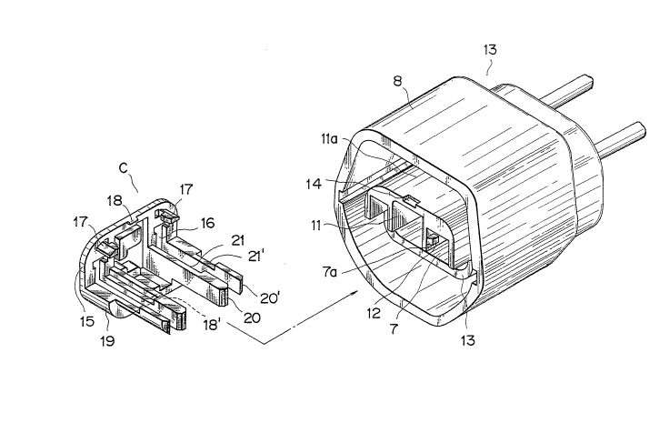
Fig. 2 is a perspective view of the insulator housing
and the locking holder shown in Fig. l;
Fig. 3 is a vertical sectional view of -the assembly of
the terminal, the insulator housing and the locking holder
under a final locked condition according to the present
invention;
Figs. 4 and 5 are views similar to Fig. 3, illustrating
incomplete insertion of the terminal; and
Fig. 6 is a vertical sectional view of the stopper
structure in the prior art.
DETAILED DESCRIPTION OF THE PREFERRED EMBODIMENTS
In the prior art as shown in Fig. 6 a flexible arm
c having a stopper projection d is formed in a terminal
receiving chamber b of an insulator housing a. The stopper
projection d is engaged with a small-diameter portion f of a
terminal e received in the receiving chamber b. A locking
plate h is inserted into a slot g of the insulator housing
a, so as to hinder flexing (displacement) of the flexible
arm c.
~lowever, in thi~ structure, the engagement between
-the stopper projection d and -the small-diameter f of the
terrninal e is weak, resulting in a small holding force being
applied to the terminal e. Therefore, there is a
possibil:i.ty of the terminal e being disengaged from the
insulator housing a when an electrical wire i connected to
the terminal e is 8 trongly pulled. Such a problem will
cause a serious automobile accident particularly in motion.
There will now be described a preferred embodiment
of the present invention.
Referring to Figs. 1 to 3, reference characters A,
~, _
~,i
~3
B and C designate a female housing, an insulator housing and
a locking holder.
The female terminal A includes a base portion 1,
an elec-trical contact portion Al Eormed on the forward side
of the base porti.on 1 for engaging a male terminal (not
shown), and a wire connecting portion A2 formed on the
. . ~
- 4a -
~2~37~
electrical wire 6. The base portion 1 is formed with an
opening 2 and a pair of stopper projections 3 struck out
of said base portion and projecting downwardly on
opposite sides thereof. The electrical wire 6 is
fixedly connected to the wire connecting portion A2 in
such a manner that a conductor of the wire 6 is clamped
by a conductor clamping portion 4 and an insulator of
the wire 6 is clamped by an insulator clamping portion
5.
The insulator housing B is formed with a pair of
receiving chambers 7 for receiving a pair of female
terminals A and with a hood 8 around the receiving
chambers 7 as forming an outer wall of the housing B for
receiving a mating connector (not shown). Each of the
receiving chambers 7 is provided with a flexible arm 9
having a projection 10 adapted to engage the opening 2
of the female terminal A. A cavity portion 11 is formed
between the receiving chambers 7. An inner wall 7a of
each receiving chamber 7 is formed with a temporary
locking portion 12 for temporarily locking the locking
holder C to the insulator hou~ing B. A lower half of
each receiving chamber 7 is cut out to form a recessed
portion 13. An upper wall lla of the cavity portion 11
963
is formed with a final locking groove 14 for finally
locking the locking holder C to the insulator housing B.
The loeking holder C is generally constructed of a
base 15 and a horizontal bottom portion 19 extending
substantially perpendicularly to a lower end of the base
15. The base 15 is formed with a pair of hales 16
adapted to be communicated with the receiving chambers 7
for inserting a pair of male terminals (not shown)~ A
pair of temporary locking projections 17 each having an
L-shaped configuration are formed on an inside surface
of the base 15 so as to engage the pair of temporary
locking portions 12 formed in the receiving chambers 7,
respectively. The base 15 is further formed with a
final locking pawl 18 adapted to engage the final
locking groove 14 of the insulator housing B.
Similarly, the horiæontal bottom portion 19 is formed at
its inside end with another final locking pawl 18'
adapted to engage a bottom wall llb of the cavity
portion 11 of the insulator housing B. Under the final
locking condition, the horizontal bottom portion 19 is
aligned to the recessed portion 13. The horizontal
bottom portion 19 is formed on its upper surface with a
pair of groups of bars 20 and 20' extending horizontally
from the inside surface of the base 15 and projecting
~2~ 3
from the inside end of the horizontal bottom portion 19.
The bars 20 and 20' of each group extend in
substantially parallel to each other~ and are adapted to
be inserted into each receiving chamber 7. The bars 20
and 20' are formed in their upper surfaces with stopper
grooves 21 and 21', respectively, for engaging the pair
of stopper projections 3 of each female terminal A.
In operation, the locking holder C is engaged into
the insulator housing B in s first step such that the
two pairs of bars 20 and 20' are inserted into the
receiving chambers 7, and the temporary locking
projection~ 17 are brought into engagement with the
temporary locking portions 12, thus temporarily locking
the locking holder C to the insulator housing B as shown
in Figs. 4 and 5.
Then, each female terminal A is inserted into the
corresponding receiving chamber 7 from the rear open end
thereof until it reaches a proper position where the
opening 2 of the female terminal A is brought into
engagement with the projection 10 of the flexible arm 9
of the insulator housing B. In the proper position of
the female terminal .A, the stopper projections 3 of the
female terminal A is located in registry with the
stopper grooves 21 and 21' of the bars 20 and 20' in a
-- 7 --
6~
lateral direction. Then, the locking holder C is
vertically moved while being guided by the temporary
locking portion 12 and the temporary projections 17 as
shown by an arrow P in Figs. 4 and 5 to thereby engage
the stopper grooves 21 and 20' with the ~topper
projections 3 to ensure the double engagement between
the terminal 3 and the connection housing B. At the
same time, the final locking pawls 18 and 18 of the
locking bolder C are brought into engagement with the
final locking groove 14 and the inner wall llb of the
insulator housing B, re~pectively, to perform a second
step engayement with the insulator housing. Thus, each
female terminal A is prevented from being pulled off
owing to the double engagement with both the flexible
arm 9 of the insulator housing B and the bars 20 and 21'
of the locking holder C. Furthermore, the locking
holder C is locked to the insulator housing B by the
final locking pawls 18 and 18'.
If the female terminal A is incompletely inserted
into the receiving chamber 7 as shown in Figs. 4 and 5,
the stopper projections 3 of the ~emale terminal A is in
contact with upper surEaces 20a of the bars 20 and 20lo
Accordingly, the locking holder cannot be vertically
moved in the direction of the arrow P, and it cannot be
7~6~
locked to the insulator housing B. Therefore, such
incomplete insertion of the female terminal A can be
prevented.
Although the double stopper structure as mentioned
above is applied to the female terminal in the preferred
embodiment, it may be similarly applied to a male
terminal having a similar stopperO
While the invention has been described with
reference to specific embodiments, the description is
illustrative and is not to be construed as limiting the
scope of the invention. Various modifications and
changes may occur to those skilled in the art without
departing from the spirit and scope of the invention as
defined by the appended claims.