Note: Descriptions are shown in the official language in which they were submitted.
13~231
LENS SHUTTER CAMERA INCLUDING ZOOM LENS
BACKGROUND OF THE DISCLOSURE
l. Technical Field ~-
The present invention generally relates to a lens
shutter type of auto-focus camera, and more
particularly to a zcom lens type of camera in which a -~
zoom lens system is used as a taking or photographing
optical system, and in which a finder optical system
and an electronic flash device (i.e., a strobe) are --~
associated with the zooming operation of the zoom lens ~ -
system. In other words, the finder optical system and ~
the strobe move in coordinated fashion with zooming ~ -
movement of the lens. - ~-- -
This application is related to the commonly :-
assigned Canadian Application Serial No. 536,921, - ~-
filed May 12, 1987, entitled "Zoom Lens Drive System -
for Lens Shutter Type of Camera".
2. Backaround Art
Generally, in conventional lens shutter (i.e., ~-~
between the lens shutter) types of auto focus cameras,
it is impossible to vary the focal length of the ~-
photographic optical system. Other lens shutter types
of auto focus cameras comprise a two focal length
system, in which a lens is provided for varying the
focal length and can be selectively inserted in the
photographing optical system. In such a system, two
focal lengths are provided; however, it is possible to
use only the two focal lengths provided, e.g., a wide
angle and a telephoto range for the zoom lens, or,
e.g., a standard range and a telephoto range for the
zoom lens. While taking advantage of such dual focal ~
lengths, it is impossible to cover the range of focal -
lengths between the two extreme focal lengths, or
between a wide angle and a medium telephoto focal
length. Under such circumstances, taking pictures
with the use of a zoom lens has heretofore only been --
possible by using a single lens reflex camera.
~ '.'.',.'
: '-' ~ .
1312~
-- 2
However, single lens reflex cameras are more
expensive and heavier than lens shutter type cameras,
and, accordingly, it is not easy for a photographer
who is unfamiliar with cameras to freely use such
single lens reflex cameras. secause of the heavy
weight and relatively large size of such single lens
reflex camer~s, female photographers and travellers
who are desirous of reducing the weight and the amount
of baggage carried tend to hesitate to use such a
single lens reflex (hereinafter SLR) camera, even if
they appreciate the high quality pictures which are
generally taken by such cameras. ~ ~
Accordingly, users who would otherwise hesitate
to use single lens reflex cameras which are relatively
bulky and heavy, as noted above, have only two
alternate choices: (a) a relatively small, light lens
shutter type of automatic camera which has heretofore
not been capable of controlling the focal length of
the photographing optical system; or (b) a dual focal -~
length type of auto focus camera in which only two
extreme focal lengths can be used.
One aspect of one embodiment of the present
invention provides a small, light, compact lens
shutter type of camera with a zoom lens in which
focusing control and electronic flash or strobe
control can be automatically effected.
Another aspect of another embodiment of the
present invention provides a lens shutter type of
autofocus camera which has an additional macro (i.e,
close-up) function with which a~ extremely large,
detailed image can be taken; and in which a finder
optical system and an electronic flash device are
adapted to be coordinated with zooming operation of
the zoom lens in the macro mode as well as in normal
operation (e.g., in wide angle, telephoto or standard
operation).
:-
1312231 ~ ~
Yet another aspect of another embodiment of the -
present invention provides ii~ movable macro - -~
compensating optical element which is used in the
distance measuring apparatus or range finder in order --
to extend the optical base length from its value in
the normal photographic mode, and to enable -
substantially the same area on the position detecting ~-~
sensor to receive light when measuring the distance of
a subject.
Still another aspect of another embodiment of the -:
present invention provides a camera having a field of ~ -
view with minimum parallax in the macro mode.
Another aspect of another embodiment of the
present invention reduces parallax in a lens shutter
type camera by providing a prism selectively movable ~ ~
into the path of a finder optical system in order to ~ -
deflect the field of view downwardly and rightwardly
to the axis of the photographing optical system when
the camera is in its macro photographing mode.
Still a further aspect of another embodiment of -
the present invention moves a strobe lamp assembly
along an optical axis thereof in coordination with
movement of a zoom lens.
Yet another aspect of another embodiment of the
present invention provides a distance measuring device
used in an auto-focus lens shutter type of camera in
which an optical wedge is selectively inserted to
extend the optical base length between the light
emitter and the light receiver comprising the distance
measuring device. ~
Still another aspect of another embodiment of the ;~ :
present invention provides a finder optical system in
which it is necessary to move only a single lens to
vary the field of view. ~ -
Another aspect of another embodiment of the
present invention provides a lens shutter type camera -~
with a light intercepting assembly which minimizes
.: .
1 31223~
light from entering a photographic optical assembly
lens system.
Still a further aspect of another embodiment of
the present invention provides a lens shutter type of
camera which includes a strobe assembly whose -
illumination angle varies in accordance with the
position of a movable zoom lens assembly.
Yet another aspect of another embodiment of the
present invention provides a lens shutter type camera
in which a flexible printed circuit board is guided in
its movement along one side of a cam ring and zoom
lens, and which includes structure for minimizing
internal reflections from the FPC board into the
interior of a photographing optical assembly. ---
DISCLOSURE OF INVENTION
The present invention provides, in a preferred
embodiment, a lens shutter type of camera having a
subject distance measuring device, a photographing
optical system which is driven in response to
measurement of the subject distance which is detected
by the subject distance measuring device, a finder
optical system which is independent of the
photographing optical system, and a strobe. In
accordance with another preferred embodiment of the
present invention, the photographing optical system
comprises a zoom lens assembly which is capable of -
successively varying the focal length of this optical -
system; the finder optical system is independent of
the photographing optical system and comprises a
variable power finder optical lens assembly which is
capable of varying the field of view of the finder
lens assembly, in accordance with the specific focal
length of the zooming lens system at any point in
time; and the zoom lens system and the variable power - ~
finder optical system are driven by a single zooming -
motor. - -~
;- :
.~: '
13~ ~23~
- 5 -
With such an arrangement, only the zooming
operation and the shutter release operation will be -
manually effected, resulting in a high quality,
compact automatic camera.
The lens shutter type of camera of a preferred
embodiment used in the present invention is
functionally equivalent, or in fact superior, to a
single lens reflex camera, insofar as it incorporates
a strobe device, thereby providing a highly
systemitized, auts-focus camera which is easy to use
and handle.
The strobe device can be of a type, e.g., in
which the illumination angle will be fixed, but is
preferably a variable illumination angle strobe device
which is capable of varying the illumination angle in
accordance with, or in response to, the variable focal
length of the zoom lens system.
In accordance with one embodiment of the present
invention, the zoom lens system can either be
partially or completely moved in the direction of the
optical axis of the photographing optical system,
beyond one of the focal length extremities, when the
camera is placed into the macro mode. Another feature
of one embodiment of the present invention is that the
finder optical system comprises a variable power
finder optical system which ~ncludes an optical
element which is capable of varying the field of view,
the optical element varying the field of view in
accordance with or in response to the particular focal
length of the zoom lens system. The finder system
includes an optical element which is capable of -~
deflecting the finder optical axis towards the optical
axis of the photographing optical system in order to
correct parallax in the macro mode of the camera.
In accordance with yet another feature of another
preferred embodiment of the present invention, a
strobe device comprises a variable illumination angle
strobe device which is capable of varying the strobe
131223~
- 6 -
illumination angle in accordance with the focal length
of the zoom lens system and in association with or in
~ response to movement or transfer of the zoom lens
-~ (photographing lens) system into the macro mode.
- The subject distance measuring device of the
present invention is capable of detecting the subject
distance by a conventional triangulation measuring
method, which has been adopted to ensure precise
', 10 detection of the subject distance, even when the
~ camera is in its macro mode; this distance measuring
'~,t device includes an optical element which is capable of
deflecting the distance measuring light in order to
~ optically extend the base length of the measuring
'`7 device in response to transfer or movement of the zoom
lens system into the macro mode.
In one preferred aspect of the present invention
a lens shutter type of auto focus camera is provided
which has a zoom lens which is continuously movable
between an extreme wide angle position and an extreme
telephoto position. The lens is movable beyond the ~-~
extreme telephoto position into a macro or close-up
photographing position; and it is movable beyond the ~--
extreme wide angle position into a closed position in
which the photographing lens is completely collapsed -~
and in which lens barriers are provided to close an
opening in a lens barrier block. The finder field of -~
view and strobe illumination angle in the camera vary
in accordance with the zooming operation of the lens,
as well as when the picture of a subject is taken in a
macro mode at a close distance. Focusing can be
automatically controlled in both the macro mode and in
any range of the zooming lens. An optical wedge is
adapted to be positioned along the optical path of the
distance measuring device which forms a portion of the
automatic focusing system of the camera. A prism is
adapted to be pivoted into the optical path of the
finder optical system in order to correct for parallax
:.
,~ . .
1312231
,....
- 7 -
in the macro mode. A cam plate is provided which is driven
by a single motor, which also drives the zoom lens via a
cam ring; and the cam plate is adapted to drive the finder
optical system and the strobe light assembly in accordance
with zooming operation of the zoom lens.
In accordance with an embodiment of the present
invention there is provided a camera having a finder
optical assembly and a photographic optical assembly with
different optical axes, the photographic optical assembly
including a movable zoom lens, the camera further
comprising a strobe assembly, and means for driving the
zoom lens, for driving the finder optical assembly in
association with zooming movement of the zoom lens in order
to vary the field of view through the finder optical
assembly and for driving the strobe assembly in association
with zooming movement of the zoom lens, the means for
driving the zoom lens, the finder optical assembly and the
strobe assembly, including at least one gear positioned
about at least a portion of the zoom lens, the gear being
rotatable in association with linear movement of the zoom
lens along the photographic optical axis.
Preferably there is further provided a generally
cylindrical rotatable cam ring positioned about the zoom
lens and driven by a motor, the at least one gear being
positioned about at least a portion of the cam ring,
wherein the motor, the gear, and the cam ring together
comprise means for zooming the lens along the photographic
optical axis. It is particularly preferred that the gear
be a sector gear attached to the outer periphery of the cam
ring and comprises means for rotating the cam ring when the
sector gear is driven by the motor.
In a preferred embodiment, the zoom lens includes
a front lens group and a rear lens group and the cam ring
~I i .,. ~ . :
. , , ~ ~ .L . . . : ' ' '
. ' ' ' " . .
1312231
has a front lens cam groove and a rear lens group cam
groove for slidably receiving pins attached to frames for
each of the lens groups. It is particularly preferred that
the front lens group is adapted to be engaged by a pin on
a frame which surrounds the front lens, and the rear lens
group is adapted to be engaged by a pin attached to a rear
lens group frame.
The front lens cam groove, in a particularly
preferred embodiment, includes a shutter block opening and
closing section, and an extreme wide angle position section
which the shutter block pin engages when the cam ring
travels over an angle 01~ a variable magnification section
which the shutter block pin engages when the cam ring
travels over an angle 2~ and an extreme telephoto position
section, a macro transfer section, and an extreme macro
fixing section which a shutter block pin engages when the
cam ring travels over the angle 03, wherein the rear lens
groove includes an extreme wide angle position section
which the rear lens group frame pin engages when the cam
ring travels over an angle 01~ a variable magnification
section which the rear lens groups frame pin engages when
the cam ring travels over the angle 2~ and an extreme
telephoto position which the rear lens group frame pin
engages when the cam ring travels over the angle 03.
In accordance with another embodiment of the
present invention there is provided a camera having a
finder optical assembly and a photographic optical assembly
with different optical axes, and a movable zoom lens,
forming part of the photographic optical assembly. ~he
camera further comprises means for moving the finder
optical assembly in association with zooming movement of
the zoom lens in order to vary the field of view through
the finder optical assembly, a strobe assembly, and means
: -: -
:.: :
. ~, ~ , ,
'~ :, ~, a ' ~ ' :
~31223~
g .~
for moving the strobe assembly in association with zoomingmovement of the zoom lens, wherein the finder optical
assembly comprises a first lens group having a stationary
positive lens and a movable negative lens, the positive
lens being adapted to be closer to a subject being
photographed by the camera than the negative lens, a second
lens group comprising at least one stationary negative
lens, and a third lens group comprising at least one
stationary positive lens, wherein the first lens group is
closest to the subject along the finder optical assembly
optical axis and wherein the third lens group is located
farthest from the subject along the finder optical assembly
optical axis, the finder optical assembly thereby
comprising at least two stationary lenses and at least one
movable lens positioned between the at least two stationary
lenses.
In accordance with another embodiment of the
present invention there is provided a camera having a
finder optical assembly and a photographic optical assembly
with different optical axes, the photographic optical
assembly including a zoom lens. The camera further
comprises means for moving the finder optical assembly in
association with zooming movement of the zoom lens in order
to vary the field of view though the finder optical
assembly, a strobe assembly, and means for moving the
strobe assembly in association with zooming movement of the
zoom lens. The camera further comprises means for
automatically focusing the camera by measuring the distance
of a subject from the film plane of the camera by
triangulation, the camera further comprising means for
extending the base length of the distance measuring device
in a macro camera mode when the lens is located beyond an
extreme telephoto position, the base length extending means
, . .
: :
1312231
-- 10 --
comprising an optical wedge which is movable into the axis
of a light receiver forming part of the distance measuring
means.
A further embodiment of the present invention
provides a camera having a finder optical assembly and a
photographic optical assembly with different optical axes,
the photographic optical assembly including a zoom lens.
The camera further comprises means for moving the finder
optical assembly in association with zooming movement of
the zoom lens in order to vary the field of view through
the finder optical assembly, a strobe assembly, and means
for moving the strobe assembly in association with zooming
movement of the zoom lens. The camera further comprises
means for automatically focusing the camera by measuring
the distance of a subject from the film plane of the camera
by triangulation, the camera further comprising means for
extending the base length of a subject distance measuring
device when the camera is placed into a macro photographic
mode.
In a still further embodiment, the present
invention provides a camera having a finder optical
assembly and a photographic optical assembly with different
optical axes, the photographic optical assembly including
a zoom lens. The camera comprises means for moving the
finder optical assembly in association with zooming
movement of the zoom lens in order to vary the field of
view through the finder optical assembly, a strobe
assembly, and means for moving the strobe assembly in
association with zooming movement of the zoom lens, wherein
the zoom lens comprises a front lens group and a rear lens
group. The camera comprises a shutter block mounted around
the front lens group.
In accordance with yet another embodiment of the
' , .
131223~ ~-
present invention there is provided a camera having a
photographic optical assembly and a finder optical
assembly, the optical assemblies having different optical
axes, the photoyraphic optical assembly including a zoom
photographing lens with at least one movable lens group for
varying the optical length of the zoom lens, the finder
optical assembly comprising at least one movable lens for
varying the finder field of view in accordance with the
focal length of the zoom lens, and a variable illumination
angle strobe assembly with a lamp which is movable in
accordance with the focal length of the zoom lens system.
The camera further comprises a gear positioned about at
least a portion of the zoom lens, the gear being rotatable
in association with zooming movement of the zoom lens to
thereby form at least part of a driving system which
comprises means for moving the finder optical assembly and
the strobe assembly along substantially linear paths in
response to movement of the zoom lens along the optical
axis.
In accordance with yet another embodiment of the
present invention there is provided a camera having a
finder optical system and a photographic optical system
with different optical axes, the photographic optical
system comprising a zoom photographing lens with at least
one movable lens group for varying the optical length of
the photographic optical system, the finder optical system
being separate from the photographic optical system and
having at least one movable lens for varying the finder
field of view in accordance with the focal length of the
zoom lens and a variable illumination angle strobe assembly
with a lamp which is movable in accordance with the focal
length of the zoom lens, and a driving member which moves
in association with movement of the moveable lens group,
:"
. - :' - -
- ''
1312231
,
- 12 -
the driving member comprising means for moving the finder
optical system and the strobe assembly, the driving member
being driven by an exterior surface of a substantially
annular member surrounding the movable lens group, wherein
the driving member comprises a cam plate, a first pin
engaged in one opening on the cam plate, the first pin
being attached to the finder optical system, and a second
pin engaged in a second opening of the cam plate and
attached to the strobe assembly.
In a still further embodiment, the present
invention provides a camera having a finder optical system
and a photographic optical system with different optical
axes, the photographic optical system including a zoom lens
movable along the photographic system optical axis, and a
strobe assembly, both the finder optical system and the
strobe assembly being movable along respective axes which
are substantially parallel to the photographic system
optical axis. The camera has a gear positioned about at
least a portion of the zoom lens and being rotatable about
the photographic axis in association with zooming movement
of the zoom lens, the camera further comprising means for
converting rotational movement of the gear into
substantially linear movement of the finder optical system
and strobe assembly along the parallel axes.
A further embodiment of the present invention
provides a camera having a finder optical assembly and a
photographic optical assembly with different optical axes,
the photographic op~ical assembly including a movable zoom
lens. The camera further comprises a strobe assembly and
means for moving the zoom lens and for moving the finder
optical assembly in association with movement of the zoom
lens in order to vary the field of view though the finder
optical assembly, the moving means including at least one
. .
','. ',,: -
:
-~
~312231 ~ ~
- 12a -
.., ~ ,,
gear positioned about at least a portion of the zoom lens,
the gear being rotatable in association with zooming
movement of the zoom lens along the optical axis.
In accordance with yet another embodiment of the
present invention there is provided a camera having a
finder optical assembly and a photographic optical assembly
having a movable zoom lens, means for moving the finder
optical assembly in association with zooming movement of
the zoom lens in order to vary the field of view through
the finder optical assembly, a strobe assembly, and means
for moving the strobe assembly in association with zooming
movement of the zoom lens. The camera includes a motor for
driving the zoom lens, and for driving the finder optical
assembly and the strobe assembly in association with
zooming movement of the zoom lens, wherein the camera
includes only one motor and wherein the motor is positioned
above the zoom lens.
A still further embodiment of the present
invention provides a camera having a finder optical
assembly and a photographic optical assembly with different
optical axes, the photographic optical assembly including
a zoom lens, the camera comprising means for moving the
finder optical assembly in association with zooming
movement of the zoom lens in order to vary the field of
view through the finder optical assembly, and a strobe
assembly, wherein the zoom lens comprises a front lens
group and a rear lens group, the camera comprising a
shutter block mounted around the front lens group.
In accordance with yet another embodiment of the
present invention there is provided a camera having a
photographic optical assembly and a finder optical
assembly, the photographic optical assembly including a
zoom lens, the optical assemblies having different op~ical
',- ~'~ ' ' .' '',
:
.
''.'',''..,'',~
1312231 ~ ~
- 12b -
axes, the zoom lens having at least one movable lens group
for varying the optical length of the system, the finder
optical assembly comprising at least one movable lens for
varying the finder field of view in accordance with the
focal length of the zoom lens. The camera further
comprises a strobe assembly and at least one gear
positioned about at least a portion of the zoom lens, the
gear being rotatable in association with zooming movement
of the zoom lens to thereby form at least part of a driving
system which comprises means for moving the finder optical
assembly along a substantially linear path in response to
movement of the zoom lens along the photographic optical
axis.
A still further embodiment of the present
invention provides a camera having a finder optical
assembly and a photographic optical assembly with different
optical axes, the photographic optical assembly including
a zoom lens movable along the photographic system optical
axis, the finder optical assembly being movable along an
axis which is substantially parallel to the photographic
system optical axis. The camera has a strobe assembly and
a gear positioned about at least a portion of the zoom lens
and being rotatable about the photographic system optical
axis in association means for converting rotational
movement of the gear into substantially linear movement of
the finder optical system along the parallel axis.
Other aspects, featureæ and advantages of the
present invention will hereinafter be described.
BRIEF DESCRIPTION OF DRAWINGS
The above and other aspects, features and
advantages of the present invention will be described in
greater detail with respect to the accompanying drawings,
.: '
. .
1 3 1 2 2 3 ~ ~
- 12c -
in which like reference numerals represent similar elements :
throughout the several views, and wherein:
Fig. 1 is a schematic perspective view of a first - . .
embodiment of a lens shutter type of camera having a zoom : -:
lens formed in accordance with the present invention;
Fig. 2 is a front elevational view of a lens .
barrel block, a light emitter, a light receiver, and a .
macro-compensating optical element which forms a part of a ~: -
distance measuring device, together with a zooming motor, :
all forming a portion of the invention of Fig. l;
Fig. 3 is a top plan view of the apparatus of ~ .
Fig. 2; :::
,
''':'
13i~231
P5713S01
-13-
Fig. 4 is a sectional view taken along line IV-IV of
Fig. 2:
Fig. 5 is a sectional view of the apparatus of Fig. 2
taken along line V-V of Fig. 2:
Fig. 6 is a longitudinal ~ectional view of a lens
barrel block and two photographing optical lenses formed in
accordance with the present invention:
Fig. 7 is a developed view of the camming ~ -
grooves in a "flattened" cam ring u6ed to surround the
lo front and rear len~ element groups of the photographic
optical system of the camera of Fig. 1:
Fig. 8 is an exploded perspective view of a lens barrel
block used in the camera of Fig. 1:
Fig. 9 i~ a sectional view illustrating an optical
arrangement for adjusting the focus point of the camera when
the camera iB placed into its macro mode:
Fig. 10 is an enlarged plan view of the prism, frame
(i.e., mask) and one light receptor lens of the system of
Fig. 9:
Fig. 11 is a front elevational view illu~trating the
as6embly of Fig. 10;
Fig. 12 is a sectional view of an optical arrangement
used in a two lens group zooming lens in the camera of Fig.
l; ~.' ."
Fig. 13 is a schematic view illustrating the light
emitter and light receptor of a distance measuring device
used in the camera of Fig. l;
Fig. 14 i8 a sectional view of an optical arrangement
of a system for ad~usting the focal point of the ob;ect
30 distance measuring system when the camera i8 in a macro :
mode; -
Figs. 15A - 17A are vertical sectional views of a first ~- -
embodiment of a finder optical system used in accordance
with the present invention, in which:
Fig. 15A i8 a side plan view of the finder optical -~
assembly when in a wide field, small magnification position;
13~ 2231 ~ ~
P5713S01 - 14-
Fig. 16A iB a plan view of the assembly of Fig. 15A
when the camera is in a narrow field, large magnification
mode:
Fig. 17A i6 a plan view of the assembly of Fig. 15A
when the camera is in a narrow field, large magnification
position when the camera is in its macro mode;
Figs. 15B, 16B and 17B, respectively, illustrate the
aberrations of the optical ~ystems of Figs. 15A, 16A and
17A, respectively;
Figs. 18A-20B are all vertical sectional views of a
second embodiment of a findor optical system formed in
accordance with the present invention in which:
Fig. 18A is a plan view of the optical system when the
camera i~ in a wide field, small magnification mode;
Fig. l9A is a plan view of the optical system when the
camera is in a narrow field, large magnification mode; and
Fig. 20A i6 a plan view of the optical system when the
camera is in a narrow field, large magnification macro mode;
Figs. 18B, l9B and 20B, respectively, are all views
illustrating the aberrations for the finder optical a~sembly
when it is in the positions of Figs. 18A, l9A and 20A,
respectively;
Fig. 21 is a plan view of a cam plate which can be
attached to a portion of the finder block and the strobe
lamp assembly of the present invention;
Fig. 22 is a sectional view taken along line XXII-XXII
of Fig. 21;
Fig. 23 is a back plan view of the cam plate of Fig.
21;
Fig. 24 is a plan view of the apparatus of Fig. 21 with
the cam plate removed;
Fig. 25 i6 a sectional view taken along line XXV-XXV of
Fig. 21;
Fig. 26 is a sectional view taken along line XXVI-XXVI
of Fig. 25 showing the finder plate in a first position;
Fig. 27 is a sectional view similar to that of Fig. 26
13122~ :
P5713S01
- 15-
but illustrating the finder plate in a second, operational
position;
Fig. 28 is a sectional view similar to the view of Fig.
26, in which a deflecting prism actuating plate has been
removed to facilitate consideration;
Fig. 29 is a front elevational view of the apparatus of -
Fig. 25, shown in a position in which a deflection prism
actuating plate is inserted;
Fig. 30 is a sectional view taken along line XXX-XXX of
Fig. 29:
Figs. 31 and 32 are sectional views of a first
embodiment of an optical barrier mechanism, as viewed along
a plane which i8 perpendicular to an optical axis, when in
its open position with the central lens frame opening being
open;
Fig. 32 i5 a sectional view similar to that of Fig. 31
but illustrating the optical barrier mechanism when it is in
its clo~ed position; --
Fig. 33 iB a sectional view of a second embodiment of
20 an optical barrier mechanism formed in accordance with the -
present invention, the view being similar to that of the
first embodiment of the optical barrier mechani~m
illustrated in Fig. 31; -~
Fig. 34 is a sectional view of the optiaal barrier
mechanism of Fig. 33 in its closed position, similar to the
view of the embodiment of Fig. 32;
Fig. 35 is an exploded perspective view of a light
intercepting mechanism positioned ad~acent to a lens barrel
block; -
Fig. 36 is a perspective view of a light intercepting
ring;
Fig. 37 is a sectional view taken along line XXXVII-
XXXVII of Fig. 36;
Fig. 38 is a sectional view of a second embodiment of a
light intercepting ring formed in accordance with the
present invention which is similar to the view of Fig. 37;
1312231
P5713S01
- 16-
Fig. 39 is an exploded perspective view of one
embodiment of a guiding device for a flexible printed
circuit board (i.e., an FPC) with the cam ring being
partially cut away;
Fig. 40 is a perspective view of the FPC board guide
member of Fig. 39:
Fig. 41 is a sectional view of a mechanical arrangement
of an FPC board guide plate with respect to the space
defined between the cam ring and a front lens group frame;
Fig. 42 i8 a side elevational view of an FPC board
which is illustrated in extension (in dashed lines) and in a
deformed position (in solid lines), respectively;
Fig. 43 is a side elevational view of a light
intercepting means used in association with an FPC board;
Fig. 44 is a developed or schematic view of a code
plate, with the lens of the code plate and grooves of the
cam being illustrated on a flattened cam ring, illustrating
the functional relationship between conduative lands on the
code plate and the cam (ring and plate) grooves;
Fig. 45 i5 a table illustrating the zoom code on the
code plate of Fig. 44 and the stopping positions which are
located on the code plate;
Fig. 46 is a front elevational view of the operational
switches of a camera formed in accordance with the present
invention:
Fig. 47 i6 a back elevational view of the camera of the
present invention illustrating a zooming lens operation
switch thereon;
Fig. 48 is a top plan view of the camera of Figs. 46
and 47, illustrating additional operational switches;
Fig. 49 i5 a schematic sectional view illustrating a
mode changing switch formed in accordance with the present
invention in a first, inoperative position;
Fig. 50 is a sectional view of a mode changing switch
and a macro button illustrated in a second operational
position;
1312~31
P5713Sol
-17-
Fig. 51 is a schematic view of an alternative
telephoto-wide angle switch of the camera of the present
invention;
Fig. 52 is a front plan view of a finder optical 6ystem
lens having a plurality of bright frames thereon:
Fig. 53A is a perspective view of a double-wedge shaped
prism used in the present finder optical system:
Fig. 53B i8 a top plan view of the prism of Fig. 53A:
and
Fig. 53C is a right hand side plan view of the prism of
Fig. 53A. ~ -
BEST MODE FOR CARRYING OUT THE INVENTION
The present invention will now be described below in
greater detail, with specific reference to the accompanying
drawings whlch illustrate a variety of embodiments and
features of the present invention.
The description will be generally provided in
accordance with the following general sub headings:
A. The Overall Camera Construction for a Lens Shutter
Type of Camera
B. Distance Measuring Device, i.e., Range Finder, and
Camera Macro Functioning Thereof
C. Finder Optical System ~ -
D. Finder and Strobe Driving Mechanisms --
E. Barrier, i.e., Lens Cap, Mechanism
F. Light Interception Assembly and Mechanism
G. FPC Board Guide and Anti-Reflection Mechanism --
H. Mechanism for Detecting Information Relating to the
Position of the Zoom Lens
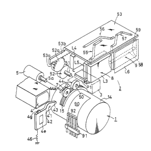
A. Overall Camera Construction for a Lens Shutter Type of
Camera
The overall construction of a lens shutter type of
camera formed in accordance with the present invention is
well illustrated in Fig~. 1-8. A lens shutter type of
camera formed in accordance with the present invention
essentially comprises a zoom lena barrel block 1, a finder
,'.~-:" ~'
. -.~.. ~ ~.
' '.' -' ~ '
~, ~b,,, .,, - , . . . ~ ,
1312~31
P5713S01
and strobe block 2 (hereinafter referred to as a finder
block), a light emitter 3 and a light receiver 4 forming a
portion of a distance measuring, i.e., AF, device, and a
zooming motor 5 which is used for the zooming operation of
the photographing optical system. All of these elements are
secured to a base 6 which forms an immovable portion of the
camera body.
Base 6 includes, as is best illustrated in Figs. 2-4, a
lens barrel supporting plate portion 6a which lies in a
plane which is perpendicular to the optical axis of the
lens; and a horizontal supporting plate portion 6b is
provided which extends at right angles from the lens barrel
6upport plate portion 6a. Support plate portion 6b extends
beyond the side edge of plate 6a, as seen in Fig. 2, in
order to support finder assembly 8 and strobe assembly 9.
The base further comprises motor supporting plate portions
6c which are positioned perpendicularly with respect to the
horizontal support plate portion 6b. Lens barrel block 1 is
supported on lens barrel support plate portion 6a, which has
a central opening (unreferenced) for receiving the lens
barrel block as illustrated in Fig. 2. A zooming motor 5 is
attached to motor support plate portions 6c and is located
above the central portion of lens barrel block 1.
Preferably, only a single such motor (e.g., a DC motor) is
used to drivingly engage all of the movable elements of the
system. A distance measuring device includes a light
emitter 3 and a light receiver 4, which are secured to the
horizontal support plate portion 6b of base 6, and which are
located on opposite sides of zooming motor 5 (see Figs. 2
and 3). Finder block 2 is ~ecured to the right hand portion
of horizontal support plate portion 6b, as viewed from the
front of the camera as seen in Fig. 2. A gear train support
plate portion 6e iB connected to motor support plate portion
6c via spacer 6f, as best illustrated in Fig. 3.
Lens barrel block 1 is adapted to be actuated by
zooming motor 5, and the construction of this block will be
:. ~ . : . . : . .. : , . . . ..
13~2231
P5713S01
--19~
described hereinbelow with more specific reference to Figs.
6-10. A rear securing plate 11 is mounted to lens barrel
support plate portion 6a of base 6 by fastening screws 10,
as is best illustrated in Fig. 6. Rear securing plate 11
5 includes four guide rods 12 which are attached to and
through bores in the rear portion of the guide plate and
which are located about the optical axis of the
photographing optical system and parallel to this axis. A
front securing plate 13 is secured to the front end~ of
10 guide rods 12; these guide rods and plates are the main
securing elements for lens barrel block 1.
A rotatable cam ring 14 is positioned between front and
rear securing plates 13 and 11, respectively; a sector gear
15 is provided about a substantial portion (but preferably
15 not the entire 360) of the outer periphery of cam ring 14;
this gear can be attached to the cam ring by conventional
means, e.g., via set screws 15a, as seen in Fig. 6; this
gear is adapted to engage, either directly or indirectly, a
first pinion 7 (Fig. 1) which is positioned between the gear
20 train support plate 6e and the motor support plate portion
6c, as seen in Figs. 3 and (particularly) Fig. 5. Gear 15
can be a sector gear which will cover a predetermined range
of rotational movement of cam ring 14: a turning recess 44a
and cam surface 44 are provided ad~acent to each other on
25 (a flat surface portion of) the gear. The cam ring is
itself provided with zooming cam grooves 20 and 21 (see Fig.
7) which are used to engage the front and rear lens element
groups, respectively.
Fig. 7 is a schematic or developed view of zooming cam
30 grooves 20 and 21 of ring 14. Cam groove 21, used to engage
the rear lens element group, includes an extreme wide angle
fixing section 21a, a variable magn~fication section 21b
inclined upwardly (as seen in Fig. 7) from section 21a, and
an extreme telephoto fixing section 21c. Cam groove 20,
35 used for the front lens slement group, includes a section
20a for opening and closing barrier block 30, a lens
,
13~2231 ~ ~
P5713SOl
-20-
retraction section 2Ob, an extreme wide angle fixing section
20c, a variable magnification section 20d, an extreme
telephoto fixing section 20e, a macro transfer section 20f,
and an extreme macro fixing section 20g.
When the term macro is used throughout this
specification, it refer~ to a "close-up" photographing
configuration for the camera. Previously, the term "macro"
has occasionally been used to mean "bigger than life":
however, the term macro has been used throughout this
specification as an equivalent term for close-up, and
whenever it i~ used it should be taken to have such a
meaning unless indicated to the contrary herein.
The total angle 0 1 of the rotational displacement of
cam ring opening and closing section 20a, lens retraction
section 20b, and extreme wide angle fixing section 20c of
zooming cam groove 20 is identical to angle 0 1 of the
extreme wide angle fixing section 21a of zooming cam groove
21. Angle 0 2 of the variable magnification, i.e., variable
power, section 20d of zooming cam groove 20 is identical to
angle 0 2 of the variable magnification, i.e., variable
power, section 21b of zooming cam groove 21. Further, the
total angle ~ 3 of the extreme telephoto fixing section
20e, the macro position fixing section 20g, and the macro
transfer section 20f, is equal to the angle 0 3 of the
extreme telephoto fixing section 21c. In the illustrated
embodiment, the zooming range is between approximately 35mm
and approximately 7Qmm.
A roller 17, as illustrated in both Figs. 6 and 8, is
positioned within zooming cam groove 20: this roller is
attached to a front lens group frame 16. A roller 19 of
rear lens group frame 18 is positioned within zooming cam
groove 21, again as illustrated in Figs. 6 and 8. Front
lens group frame 16 and rear lens group frame 18 are movably
guided by guide rods 12, and a decorative frame 22 and
shutter block 23 are secured to the front lens group frame
16 via set screws 22a, as best ~een in the exploded view of
1312231
- 21 -
Fig. 8, as well as in the cross-sectional view of Fig.
6.
The front lens frame 24 which supports front lens
element group Ll is engaged by shutter block 23 via
helicoid 25, which is shown in Fig. 8. Front lens
frame 24 includes an arm 24a which engages lens
feeding lever 23a of shutter block 23 (see Fig. 6), so
that when lens feeding lever 23a rotates in a
circumferential direction in order to rotate front -
lens frame 24, the front lens frame will move along
the direction of the optical axis of the photographing
optical system under the guidance of helicoid 25.
Rear lens element group L2 is directly attached to
rear lens group frame 18, as seen in Fig. 6. One
desired configuration of lens groups L1 and L2, as
illustrated in Fig. 6, are disclosed in commonly
assigned U.S. Patent No. 4,720,179.
The structure of shutter block 23 is known per
se. This shutter block rotates lens feeding lever 23a
over a predetermined angular displacement in ~ -
accordance with a detection signal which is received
by the shutter block from the distance measuring
device, as described hereinafter, via a pulse motor
which is incorporated within the camera body and which
is adapted to open shutter sector 23b, which has been -~ -
closed for a predetermined time, and to thereafter -
return lens feeding lever 23a into its original
position after the shutter has again closed. This
type of shutter block is disclosed, e.g., in
unexamined Japanese Published Patent Application
(KOKAI) No. 60-235,126 dated November 21, 1985. The
present camera utilizes such a shutter block in the
fundamental way disclosed therein. ~-
Finder block 2 includes finder assembly 8 and -~
strobe assembly 9. The finder device and the strobe
device are adapted to vary, respectively, the field of
finder view and the illumination angle, i.e., the -
intensity of the strobe, ~
..- - .':
,- -- ,. . ~
1312~31
P5713S01
-22-
in accordance with variance in the focal length of the lens
barrel block 1. Zooming motor 5 is used as a power source
both for finder control and strobe control; only a single
motor need therefore be used.
As seen in Fig. 1, sector gear 15 of cam ring 14 is
engaged by a second pinion 50 which is different from the
first pinion 7 referred to previously. Shaft 51, to which
pinion 50 is attached, extends rearwardly towards the rear
portion of base 6, and is provided with a reduction gear
train 52 adjacent a rear end of the shaft. The reduction
gear train include~ a final gear 52a which meshes with a
rack 53a of movable cam plate 53. This substantially flat
cam plate 53 i8 slidable in right and left hand lateral
directions, as viewed in Fig. 1, and includes a downwardly
bent portion 53b at its rear end, as best shown in Fig. 1.
Rack 53a is formed on the lower end of bent portion 53b of
cam plate 53. Reduction gear train 52 i8 adapted to reduce
rotation of gear 15 in order to restrict or limit the
lateral movement of cam plate 53. The cam plate is provided
with a variable power cam groove 55 for guiding movement of
finder device 8, a parallax correction cam groove 56, and a -
strobe cam groove 57 for guiding movement of strobe device
9.
The lens system used in finder optical assembly 8
essentially comprises a subject lens group L3, an eyepiece
group L4, and a movable variable power lens group L5, and -
further comprises a deflection prism Pl which is used when
the camera is placed into the macro or close-up mode. - -
Variable power lens group L5 make~ the image picture
size, which is adapted to vary in accordance with the
variable power operation of lens barrel block 1, be
coincident with the field of view in finder device 8.
Deflection prism Pl will enter the optical path of the
finder lens system only in the macro mode, in order to
adjust parallax which otherwise occurs in such mode.
Specifically, parallax which inevitably occurs when using
131 2231
P5713S01
-23 -
lens shutter type of cameras will increase as the subject
whose picture is being taken approaches the camera: and,
accordingly, a large parallax would normally result in the
macro mode. In order to solve this problem and reduce the
large parallax which otherwise occurs in the macro mode,
deflection prism Pl is provided in the form of a wedge with
a thicker lower end and a thlnner upper end. Deflection
prism Pl, when located along the optical axis of the finder
optical system, serves to deflect rays downwardly in order
to take a picture of a subject which i8 located extremely
close to the camera. Fig. 28 illustrates the optical path
of light rays when the deflection prism Pl is located along
the optical axis of the camera. As described hereinafter,
the wedge prism which is used is preferably selected to be a
double wedge prism, which varies in width in both the
vertical and in the horizontal directions, as clearly
illustrated in Figures 53A, B and C. The use of such a
prism bends the light rays downwardly and rightwardly, to
move them into substantial alignment with the photographic
optical axis.
Strobe assembly 9 restricts or limits the illumination
angle when the focal length of the photographing lens is
large, namely, as the zoom lens is fed forwardly; and the
strobe assembly 9 is moved to increase the illumination
angle in the macro mode, in order to decrease the amount of
light which reaches the subject. In the embodiment
illustrated, strobe device 9 includes a fixed Fresnel Lens
L6, a movable concave reflector 59, and a xenon lamp 58
which can be moved along the direction of the optical axis
of the strobe. Alternately, a simple strobe could be used
in which the illumination angle would be fixed. Although
such a strobe arrangement is possible, it is preferable to
move the lamp in the optical axis direction in accordance
with movement of the zoom lens in order to optimize the
quantity of light given to a sub~ect during photography,
dependent upon the position occupied by the photographing
,.: ',:
1312%~1
P5713S01
- 24 -
optical system in the zoom lens.
B. Distance Measuring Device, i.e., Ranae Finder, and Camera
Macro Function
Before looking in a detailed fashion at the distance
measuring device of the present invention and its
relationship to the macro function of the camera, the
relationship between the distance of a sub~ect from the two
lens group zoom lens and the displacement or forward feed of
the zoom lens will be now be discussed.
Fig. 12 illustrates a relatively simple construction
for a two lens group zoom lens. In such a construction, the
distance of the sub~ect and the displacement of the zoom
lens have a relationship as follows:
U=fl (2+X/fl+fl/X) + HH + ~ ...(1), wherein:
U equals the distance of a sub~ect from the film plane;
fl equals the focal length of the first lens group:
X equals the displacement of the zoom lens:
HH equals the principal point distance: and
~ equals the distance between the focal point of the first
lens group and the focal point of the two lens group zoom
lens.
From equation (1) it can be calculated that:
X=(-2fl-HH-delta+U- ~ (2fl+~H+delta-U)2-4fl2~/2
...(2)
Fig. 13 illustrates the relationship between the
distance U of a sub~ect and the positional deviation (t) on
a position detection element 4a, which forms a portion of
the distance measuring device which detects the distance of
a sub~ect from the film plane based upon the principle of
triangulation.
The triangulation distance measuring device lncludes a
light emitter 3 having a light source 3a and a light
emitting lens 3b; and a light receiver 4 having a light
receiving lens 4b and a position detection element 4a, e.g.,
a photo sensitive detector (hereinafter PSD). The rays of
light emitted from light source 3a are reflected by the
1312231
P5713S01
-25-
subject, and the light reflected therefrom is received by
position detecting sensor 4a in order to detect the distance
of the subject from the film plane F. Namely, the deviation
(t) of the image on position detection sensor 4a, from a
reference point represented by the position of an image of a
subject at an infinite distance, relative to distance U of
the subject from film plane f, is given by the following
equation:
t=Lxf/(U-f-d) ...(3), in which:
L represents the base length of the distance measuring
device;
f represents the focal length of the llght receiving lens; -~
and
d representc the distance between film plane F and the focal
plane of the light receiving lens.
The deviation (t) can be detected by the electric
current, i.e., output, of position detecting sensor 4a in -
accordance with the quantity of light received by position
detecting sensor 4a, in a well known fashion. ~he
photographing opt~cal ~ystem of the camera i8 ad~usted to
form an image on a focal point of the image plane in
accordance with the output signal, i.e., electric current, ~-
of position detecting sensor 4a, based upon e~uations (2)
and (3), so that automatic focusing can be effected. The
actuating or driving mechanism of the photographia optical
system is noted above.
It is necessary to shift the range of measurement of
the ~ub~ect di~tance by the distance measuring device
towards a close sub~ect distance side in order to achieve
the macro function of the camera. In the macro mode, the
photographing optical system is either partially or entirely
displaced, from a standard picture taking position, towards
the sub~ect to be taken, as is well known. ---
In the embodiment of Fig. 12, the first len~ group of --~
the photographing lens is moved forward, towards the subject
over a predetermined displacement, in the macro mode,
.
1312231
P5713S01
-26-
independently of (and beyond) the displacement effected by
the automatic focusing device during normal photography.
Fig. 14 represents one mechanism for shifting the range
of measurement of the subject distance in the macro mode in
accordance with the present invention. In Fig. 14, a
relatively conventional prism P having an apex angle of S is
inserted in front of light receiving lens 4b in order to
shift the range of measurement of the subject distance
towards the subject whose photograph is being taken. In
other words, the zoom lens camera system uses a pivotable
prism or wedge which is adapted to be positioned in front of
light receiver 4.
A~suming, e.g., that the apex angle and the refractive
index of prism P are ~ and n, respectively, the deviation tl
of the image on position detecting sensor 4a, with respect
to the sub~ect distance Ul, can be obtained as follows: -
firstly, the incident angle alpha of the rays of light on
the plane of prism P ad;acent to the sub~ect is determined
by the following equation: --
alpha=tan 1 ~L/(Ul-f-d)} + cr
Refraction angle beta of the rays of light which are
incident upon prism P having an apex angle ~ at the
incident angle alpha is determined by the following
equation: -
2~ beta=alpha- S +sin 1 tn sin ~ ~ - sin
(alpha/n))], and, therefore ~ ~~
Accordingly, deviation tl of the image on position
detecting sensor 4a will be determined by tl=f x tan ~ .
Sub~ect distance Umfl, which i8 obtained when light
which is coincident with the optical axis of light receiving
len~ 4b intersects the optical axis of light emitting lens
3b is determined as follows, provided that the thickness of
prism P i8 negllgible: -
Umfl=L/tan {sin 1 (n sin ~ ) ~ +f+d.
In one example, the present Applicants calculated the
values of U, Ul, t, tl, and t-tl, in a camera in which the
P57l3sol 131223~
-27~
photographing optical system included a two lens group zoom
lens, wherein: fl, i.e., the focal length of the first
group, equals 24.68mm; HH (i.e.,the principal point
distance) equals 7.02mm: delta, i.e., the distance between
the focal point of the first lens group and the focal point
of the zoom lens, equals 3~.04mm;
d, i.e., the distance between the film plane and the focal
plane of the light receiving lens, equals 6.292mm; the
displacement of the first group at the macro setting equals
0.5502mm.: L, i.e., the base length of the distance
measuring device, equal~ 30mm; f, i.e., the focal length of
the light receiving lens, equals 20mm.; S , i.e., the apex
angle of the prism P, equals 2.826: n, i.e., the refractive
index of prism P, equals 1.483; the distance range which can
be measured equals 0.973m~ infinity; and the number of steps
of forward feeding movement of the zoom lens is 18, so that
the range of 0.973m ~ 6m is divided into 17 forward feeding
motion steps of the zoom lens. The results of these
calculations are illustrated in Table 1 hereinbelow. In
these calculations, the distance range of 0.973m~ 6m is
shifted towards the range of 0.580m~ 1.020m.
In Table 1 hereinafter, step 17-18 represent~ a
shifting point at which the 17th step changes to the 18th
step; similarly, the step 0-1 represents a point of transfer
between 0 and the first step.
'''.'''.."
' :,-,--''
~:
~ , .. .
.~
,' :
:.
... :'
1312231
P5713S01 - 28 -
TABLE 1
POSITIONS OF IMAGES ON THE POSITION DETECTING SENSOR
AT DIFFERENT SUBJECT DISTANCES
STEP NO. U (m~ U l(m) t(mm) _l~mm) _l_t (mm)
5 17-18 6.000 1.020 0.1004 0.12740.0270 -
17 5.154 0.996 0.1170 0.14230.0253
16 4.027 0.951 0.1500 0.17190.0219 -
3.310 0.911 0.1827 0.20130.0186
14 2.814 0.875 0.2153 0.23050.0153
10 13 2.450 0.841 0.2476 0.25950.0120
12 2.172 0.810 0.2797 0.28840.0087
11 1.952 0.782 0.3115 0.31700.0055 ~- -
1.775 0.756 0.3432 0.34550.0023 -
9 1.628 0.732 0.3747 0.3738-0.0009
8 1.504 0.709 0.4059 0.4018-0.0041
7 1.399 0.688 0.4369 0.4298-0.0072 -
6 1.309 0.668 0.4678 0.4575-0.0103 -
1.230 0.650 0.4984 0.4850-0.0134 -
4 1.161 0.633 0.5288 0.5124-0.0165
3 1.100 0.616 0.5591 0.5396-0.0195
2 1.045 0.601 0.5891 0.5666-0.0225
1 0.996 0.587 0.6189 0.5934-0.0255
0-1 0.973 0.580 0.6338 0.6068-0.0270
U mfl=1.283m
As can be ~een from Table 1, an image deviation of
0.027mm occurs at the position detecting sensor 4a at the
two extremities of the range of measurement of the sub~ect
distance which can be measured, as a result of compensation
by prism P. Such a deviation corresponds substantially to
about 1 step, in the sense of the number of feeding steps of
the zoom lens. Accordingly, it iB not possible to move the
photographic lens into a correct focal point by directly
controlling displacement of the photographing optical system
in response to the output of position detecting sensor 4a,
thus resulting in an "out of focus" situation.
In other words, it i8 impossible to completely
' "'
13~2231
P5713S01 - 29 -
:
compensate for deviation in the image~ by using only prism
P, since the rate of chan~e of deviation tl of the image on
position detecting sensor 4a with respect to subject
distance Ul cannot be varied by prism P. The prism begins
5 to compensate for the image deviation, but cannot alone do
s o . ,
In view of such results, the present inventors have
found that complete compensation of such deviation can be
achieved if the rate of deviation tl is ad~usted by
lo multiplying this rate by 1.1130 (calculated by dividing
0.5334 by 0.4794), which equals the change in t from step 0-
1 to step 17-18 divided by the change in tl between step 0-1
and step 17-18, since decreases in the deviations t and tl
between steps 17-18 and 0-1 are 0.5334mm and 0.4794mm,
15 respectively. To this end, in the present invention, a
macro mode compensating optical element i8 adapted to be
selectively moved in front of the distance measuring optical
system only when the camera i~ placed in the macro mode, in
order to optically extend the base length between the light
20 emitter and the light receiver of the distance measuring
optical system, and in order to intersect the optical axis
of the light emitter and the optical axis of the light
receiver with a finite distance. Further, in this
embodiment, an actuating mechanism is provided for moving
25 the macro compensating optical element in front of the light
receiver in coordination with transfer or movement of the
photographing optical system, i.e., the zoom lens, from the
normal photographic mode to the macro mode, as discussed in
detail hereinafter.
Figure 9 illustrates an optical arrangement of the
distance measuring device when in the macro mode, in the
automatic focus camera of the present invention. In this
figure, macro compensating element 4e compri6es a prism 4c
and a mask or frame 4d, rather than only the optical wedge
oî Fig. 14. Element 4e is moved in front of light receiving
lens 4b of the distance measuring device when the camera is
.:
.
131%231
P5713SOl - 30 -
in the macro setting. In the normal photographic mode,
element 4e is retracted away from the optical axis of light
receiving lens 4b.
Prior to discussing the mechanical structure which is
adapted to actuate the compensation element 4e, the actual
construction of the macro compensating element 4e and the
reasons why measurement accuracy can be improved or
increased in the macro mode will be de~cribed in detail.
The element includes a prism 4c which i8 adapted to
optically extend the base length of the di6tance measuring
device and to refract rays of light which enter the prism.
Figure 10 illustrates in detail prism 4c, mask 4d, and
light receiving lens 4b. Fiqure 11 is a front elevational
view of Figure 10; and both of these figures illustrate how
mask or frame 4d iB capable of intercepting rays of light
out of the path of light approaching the prism. Mask 4d
includes a front opening 4f which is 6hown in the form of a
generally rectangular, elongated slot, on the (front) side
of the frame located most closely ad~acent to the subject
20 being photographed, and a rear opening 4g (see Fig. 10) on - -
the side of the frame or mask most closely adjacent to light
receiving lens 4b. Opening 4f is in the form of a slit
spaced from optical axis 0 of light receiving lens 4b by a
distance (1) which i~ measured on the opposite side of the
optical axis from light emitting lens 3b. Rear opening 4g
i8 also in the form of a elongated slit, which is
substantially located along the optical axis 0 of light
receiving lens 4b.
When prism 4c, together with mask 4d, move in front of
light receiving lens 4b, i.e., when the camera is in the
macro mode, a first lens group of the photographic lens is
fed forwardly by a constant displacement, independently of
the displacement of the lens which is fed forwardly during
the normal photographic mode by the automatic focusing
device. As best seen in Figs. 9 and 10, when prism 4c is
located in front of light receiving lens 4b, the range of
; .
131223~
P5713S01 - 31 -
measurement of the distance of the subject can be shifted to
the macro mode range. Prism 4c serves to move light
incident thereon in a parallel fashion, over a displacement
(1) in the direction of the base length, so that base length
L can be optically extended to equal the distance (L+l).
Assuming that the angle and the refractive index of
prism 4c are ~ 1~ and n, respectively, and that the parallel
displacement of light by prism 4c is represented by the ~-~
distance (1), deviation t2 of the image on position
lo detecting element 4a, as viewed with respect to the subject
distance U2, can be obtained as hereinafter detailed. -~
The incident angle of light on the plane of prism 4c
which is ad~acent to the sub~ect i8 provided by the
following equation: -
alphal=tan 1 ~(L+l)/(U2-f-d)~ + ~
This equation indicate3 that the base length of the
triangulation distance measuring *evice is extended from L
to (L+l) by the inæertion of prism 4c in front of the light
receiving lens 4b. The refraction angle betal of light
which is incident upon a prism having an angle ~ 1~ which
light is incident upon the prism at an incident angle of
alphal, is calculated in accordance with the following - -
equation: -
betal = alphal- ~ l+sin -l[nsin { ~ l-sin
(alphal/n)}], and, therefore: ~ 1 = alphal ~ ~ 1 ~ betal.
Accordingly, deviation t2 of the image on position
detecting sensor 4a is equal to f x tan ~ 1~ i.e., t2 = F x
tan ~ 1
The subject distance Umf2 which is obtained when light
coincident with the optical axis of light receiving lens 4b
intersects the optical axis of light emitting lens 3b is
yielded by using the following equation, provided that the
thickness of prism 4c is negligible:
Umf2=(L~l)/tan {sin l(n x 8in ~ 1} +f+d.
Table 2 hereinafter illustrates the results of the
calculations in which the distance measuring device of Figs.
.:
.'::.:
1312231
P5713SOl - 32 -
10 and 11 has been applied to a photographing lens -
satisfying the 6ame basic criteria as those mentioned with
respect to the embodiment of Figure 14, i.e., namely that:
(a) The photographic lens is a 2-group
lens:
(b)fl, i.e., the focal length of the
first group, equals 24.68 mm;
(c) HH, i.e., the principal point
distance, equals 7.02mm;
(d~ delta, i.e., the distance between the
focal length of the flrst lens group and
the focal length of the zoom lens, equals
~0.04 mm;
(e) d, i.e., the distance between the
film plane and the focal plane of the -
light receiving lens, equals 6.292mm;
(f) the displacement of the first lens
group in the macro setting equals
0.5502mm;
(g) L, i.e., the base length of the
distance measuring device, equals 3Omm;
(h) f, i.e., the focal length of the
light receiving lens, equals 20mm;
(i) S 1~ i.e., the angle of prism 4c,
equals 3.39:
(~) n, i.e., the refraction index of the
prism, equals 1.483;
(k) (1), i.e., the distance representing
the parallel displacement of the rays of
light, equals 3.39mm;
(1) the range of measurement of the
distance of the subject which can be
measured equal~ 0.973m~ in~inity;
(m) the number of steps of forward
feeding movement of the zoom lens is 18;
13~2231
P5713S01 - 33 -
~ ' '
(n) the range of 0.973m- 6m is divided
into 17 steps; and
(o) the photographic range of 0.973m~ 6m . -
is shifted into the range of 0.580m-
1.020m. -
1312231
P5713S01 - 34 -
TABLE 2
POSITIONS OF IMAGES ON THE POSITION DETECTING SENSOR AT
DIFFERENT SUBJECT DISTANCES WITH THE MACR0 COMPENSATION -
ELEMENT OF FIGURES 9, 10 AND 11
STEP NO. U (m) u 2(m? t(mm) -2(mm) _~-t (mm)
17-18 6.000 1.020 0.1004 0.1005 0.0001
17 5.154 0.996 0. 1170 0. 1171 0.0001
16 4.027 0.951 0.1500 0.1500 0
lo 15 3. 310 0.911 0.1827 0.1827 9
14 2.814 0.875 0.2153 0.2152 -0.0001
13 2.450 0.841 0.2476 0.2475 -0.0001
12 2.172 0.810 0.2797 0.2796 -0.0001
11 1.952 0.782 0.3115 0.3115 0
1.775 0.756 0.3432 0.3432 0
9 1.628 0.732 0.3747 0.3746 -0.0001 :-
8 1.504 0.709 0.4059 0.4059 0
7 1.399 0.688 0.4369 0.4369 0
6 1.309 0.668 0.4678 0.4677 -0.0001
1.230 0.650 0.4984 0.4984 0 :.
4 1.161 0.633 0.5288 0.5288 0 ~
3 1.100 0.616 0.5591 0.5591 0 .
2 1.045 0.601 0.5891 0.5891 0
1 0.996 0.587 0.6189 0.6190 0.0001
0-1 0.973 0.580 0.6338 0.6338 0 -
U mf2=1.283m ~ . -
It should be clearly understood from Table 2 that the
deviation of the images on the position detecting sensor 4a
30 at different ~teps between the normal photographic mode and :.
the macro mode will therefore be within +/- O.OOOlmm. This -:
is represented by the value t2-t in the last column on page :- ~
2. Accordingly, it is possible to almost completely form ~ . .
images at the focal point by ad~usting the photographic
optical system in accordance with the output of the position
detecting sensor 4a. Table 2 illustrates that prism 4c can ~- -
13~223~ -
P5713Sol - 35 -
optically extend the base length, which is normally 30mm in
a normal photography camera mode, in the macro mode 60 that
it will be 1.113 times the normal base length, i.e., the
base length will be 33.39mm when the camera is in its macro
mode: as a result, displaceme~t of position detecting sensor
4a can be increased by a factor of 1.113.
In operation, it is possible to automatically focus the
camera within any zooming range, including the macro setting
of the camera, by actuating previously discussed shutter
10 unit 23 in accordance with the output signals, i.e., the -
measurement data, which are sent by position detecting
sensor 4a. Specifically, when driving pulse~ are applied to
the pulse motor of shutter unit 23 in accordance with the
measurement data which has been received from detecting
6ensor 4a, a lens actuating or feeding lever 23a, as seen in
Fig. 8, rotates over an angle corresponding to the driving
pulses which it has received in order to rotate front lens
frame 24 together with it. AB a result of this rotation of
front lens frame 24, the front lens element group Ll is
moved along the direction o~ the photographing optical axis,
via the action of helicoid 25, in order that focusing of the
photographic lens assembly will be automatically effected. --
Lens barrel block 1 rotates cam ring 14 when zooming
motor 5 is driven. Rotation of cam ring 14 causes roller 17
25 of front frame 16 to engage the extreme macro position ~-
fixing section 20g of cam groove 20, i.e., roller moves into
6ection 20g from macro tran6fer section 20f of cam ring 14,
so that front lens element group Ll will be fed further
forwardly to move into position for macro mode operation of ~ -~
the camera.
As clearly seen in Fig~. 1 and 2, macro compensating
element 4e i8 secured to a free end of a flexible ~-
compensation or correcting flag 42, which i8 pivoted at its
base end to camera base plate 6 via a shaft 41 located below
light receiver 4. Flag 42 i~ normally retained in a
substantially 6traight position when no external force is
'' '
1311 2231
P5713S01 - 36 -
applied to the flag, and i8 elastically deformed whenever an
external force is applied to the flag. Also attached to
shaft 41, and having a pointed surface directed away from
the flag, is a projection 43, which can either be formed
integrally with the flag and attached to shaft 41, or which
can be formed separately from the flat and attached to shaft
41 at a central bore of the pro;ection. The macro
compensating element 4e is continuously and rotatably biased
into a retracted position in which it is retracted away from
the optical axis of light receiver 4 by a tension spring 46,
as illustrated in Fig. 2. As seen in Fig. 2 and (better) in
Fig. 1, cam ring 14 includes a pro~ection 44 on sector gear
15 (or on the cam ring) which engages flag projection 43 in
order to move macro compensating optical element 4e into the
optical axis of the distance measuring devlce and in front
of light receiver 4 whenever the cam ring 14 rotates to the
macro setting position. As shown in Fig. 1, a substantially
semi-cylindrical recess (or other recessconfiguration) 44a
~s provided on the gear 15 ad~acent to the camming surface
or pro~ection 44. This recess is provided to facilitate the
pivoting or rotating motion of flag pro~ection 43 as the cam
ring rotates. In other words, recess 44a is necessary to
facilitate turning movement of the pro~ection and hence
pivoting or rotating motion of optical element 4e into the
position illustrated in dotted lines in Fig. 2, in front of
l~ght receiver 4. Alternately, ring 14 or gear 15 can be
formed with a smaller diameter in order to provide
sufficient pivoting room for pro~ection 43. Camming
pro~ection 44, which effects, via its engagement with
pro~ection 43, rotationa} or advancing motion of macro
compensating optical element 4e, is positioned and
configured so that the optical element will be rotated
slightly past the position in which the element would be
aligned with the optical axis of light receiver 4. However,
the flat end of the element 4e which most closely approaches
support plate 6e which is integrally attached to base 6, is
13~2231
P5713SOl - 37 -
adapted to engage the left hand side surface of plate 6e (as
seen in Fig. 2) via a shock absorbing nub or button 4g,
shown in both Figs. 1 and 2. Accordingly, over rotational
motion of element 4e which iB effected by pro~ection 44 will
be absorbed both by the flexible flag 42, which is formed
from a resilient plastic, rubber, or other resilient
material and/or the provision of nub 4g, which will serve to
engage the side edge of plate 6e.
Thus, when cam ring 14 moves into the macro setting
position, the macro compensating optical element 4e can
automatically be brought into alignment with the optical
axis of the light receiver, into a position in front of the
light receiver, in order to optically extend the base length
between the light emitter 3 and the light receiver 4.
C. Finder O~tical Sy~tem
The finder optical ~ystem i8 best illustrated in
Figures 1 and 15-20.
The finder optlcal system is designed not only to vary
magnification between a wide field of view with a small
magnification, and a narrow field of view with a large
magnification, in accordance with the zooming operation of
the photographing lens system, but also to provide a field
of view having less parallax when the camera i~ used in its
macro mode.
One significant feature of the present invention is
that the finder optical system i8 capable of automatically
moving in association with both zooming of the photographic
lens and movement of the photographic lens into a macro
setting in order to satisfy all of the requirements of a
finder system as set forth immediately above. While
conventional finders appear to provide a plurality of bright
frames with different sizes in the field of view of the
finder, this is not a satisfactory solution to the problems
noted above, e.g., the use of such frames alone will not
minimize parallax in a macro operational mode such as that
used in the present camera.
- 13~2231
P5713Sol - 38 -
Under such clrcumstances, and in accordance with the
present invention, a finder optical device is provided in a
lens shutter type of camera having a zoom lens which
essentially comprises an improved inverted Galilean finder.
In other words, the finder optical system of the present
invention includes a first lens group having a negative
refracting power which comprises a positive lens in the form
of a fixed lens L3 and a movable negative lens in the form
of a variable power lens L5, a ~econd lens group having a
negative lens L4-1 which is one lens in a fixed eyepiece
group L4, and a third lens group having a positive
refracting power lens L4-2 which defines a second lens in
the fixed eyepiece lens group L4. A prism Pl is adapted to
be selectively moved between the positive lens L3 and the
negative lens L5 of the first lens group in order to refract
rays of light towards the optical axis. The negative lens
L5 of the first group can be displaced from a position
ad~acent to the sub~ect towards a position which is ad~acent
to a photographer's eye in order to vary the magnifiaation
from a wide field of view having a small magnification to a
narrow field of view having a large magnification. Prism
Pl, selectively brought into alignment with the optical axis
of the finder optical system, serves to decrease the
parallax when the photographic optical system is in the
macro setting and when the negative lens L5 of the first
group moves closest to the eye of the photographer along the
optical axis.
The bright frames which are illustrated in dashed lines
in Fig. 52 define the photographing ranges and are applied
to the face of the lens of the third group which is closest
to the sub~ect, i.e., on the left hand face A of stationary
eyepiece len6 L4-2 in Figs. 15A, 16A, 17A, 18A, l9A and 20A,
respectively. These yellow frames, which are placed on lens
surface A comprise a central autofocus spot (to be
positioned on the main portion of a photographic sub~ect), a
large picture area frame (for ordinary photography using the
1312231
P5713S01 - 39 -
zoom lens), and a smaller parallax correction frame (used
since the picture area will slightly narrow in the macro
mode). Further, face B of the second len~ group L4-1 which
is most closely adjacent to the eye of a photographer, is
formed from a semi-transparent material, so that a virtual
image of the bright frames which are formed by the semi-
transparent face can be enlarged and viewed through the
positive lens of the third lens group L4-2.
The yellow bright frames are positioned on the front
surface of the fixed eye piece lens L4-2 by, e.g.,
sputtering; and the rear surface of the eyepiece lens
element L4-1, i.e., surface B or r6, can be in the form of a
semi-transmissive, semi-reflective concave mirror. Light
rays emitted from (i.e., reflected by) the bright frames are
reflected rearwardly by concave surface R6 and are focused
on the viewers eye. The eye recognizes enlarged false
images of the frames in a position in the far foreground,
which images are formed via the optical effect of lenses L4-
1 and L4-2.
The negative lens L5 of the first group is movable, as
noted above, 80 that it will move from a position which it
is located adjacent to the subject into a position in which
it is more closely ad~acent to the eye of a photographer, in
order to increase the focal length of the photographic
optical system ~uring the normal zooming operation, so that
magnification can be varied from a wide field of view having
a small magnification to a narrow field of view having a
large magnification. When a picture is taken in the macro
(beyond telephoto) mode with a narrow field of view and
large magnification, a prism is inserted between the movable
lens L5 and stationary lens L3 in order to decrease
parallax, 80 that light will be refracted towards the
location of the axi~ of the photographic optical system.
Enough room is provided for the prism to pivot upwardly
for macro focusing, i.e., thereby creating a need to move
the lens L5 a relatively large distance, a~ shown in Figs.
., , , - " . ,,, . .,. , . . ~, . . ... ,,., ., ;, .. .. ... .. . .... . . . .
1~%231
P5713SOl - 40 -
16A, 17A, l9A and 20A, in order to insert the prism Pl
therein in a pivotable or rotatable fashion.
On advantage of the system is that it incorporates only
a single moving lens L5, rather than zooming a plurality of
lenses or the entire finder optical lens system and having
to thereafter compensate for such zooming movement of all of
the lenses. This serves to simplify the zooming cam plate
structure, as movement of only a single lens will suffice to
change the magnification of finder image.
The fixed viewing frames, as shown in Fig. 52, are
provided in order to avoid having to make a viewing
adjustment. The two rear eyepiece lens groups L4-1 and L4-2
which include the frames are fixed, and the curvatures of
their respective surfaces are controlled 60 that the
reflected frames will have a desired magnifiaation which is
compatible with the image magnification over the entire
range of zooming operation of the photographic lens.
The apex angle or angles of the selectively insertable
prism are defined by the re6ultant angles in the horizontal
and vertical directions, in accordance with the positions of
the optical finder system and the photographic optical
6ystem. The prism can be a single wedge ~rism, or can be a
double wedge shaped prism, a~ illustrated in Figs. 53A, 53B,
and 53C, which illustrate a double wedge prism Pll which is
advantageou~ because it is capable of bending light
downwardly and rightwardly towards the optical axis of the
photographic optical system.
As illustrated in Figs. 53, double wedge prism Pl has a
surface which increases, when viewed from the top in the
direction of arrow A tsee Figs. 53A and 53B) and which also
increases from the left hand to the right hand direction, as
viewed from the front of the camera from the photographing
optical axis, and as shown by arrow B (Figs. 53A and 53C).
In the example illustrated, the angle ~ H can be 2.8,
the angle ~3 V can be 4.2, the angle ~ H' could be
4.2, and the angle ~3 V' could be 5Ø
~' ,, :~".'
131~231
P5713S01 - 41 -
The wedge prism is adapted to be inserted between the
first convex single lens element L3 and the movable concave
single lens element L5 in a rotatable fashion. This permits
the finder unit to be made compactly and allows the prism to
be inserted between these two elements. The viewing
distance of the false image of an object and the bright
frames remain stationary throughout the zooming range of the
photographic lens, and parallax compensation is provided by
moving the prism between the lenses in the macro or close up
picture taking mode. The viewing magnification or size of
the bright frame images i~ also maintained constant
throughout the zooming range of the photographic lens, as
well as in the macrs setting, due to the placement of the
bright frames on the stationary lens element L4-2~ The
distance between the eye of a viewer and the image distance,
i.e., the diopter of the finder, virtually does not vary,
because the zooming concave lens element moves over an image
magnification of lx, or, i.e., is life size.
Parallax compensation in the macro or close up picture
taking mode is effected by positioning the wedge priæm
between the lens elements, as well as by the use of the
compensation framing marks illustrated in Fig. 52 (which is
the normal means of parallax compensation in a close
focusing mode in viewfinder type cameras). The edges of the
wedge prism are tinted green to highlight the frame that
illustrates the photographic area in the macro or close-up
mode.
Theoretically, the prism could be located in front of
the first lens group: however, by so arranging the prism, it
would increase the overall size of the finder optical
system. The prism cannot, however, be located between the
second and third lens groups, because if it were inserted
between these groups, the positions of the bright frame and
of the virtual image of the sub~ect could vary in accordance
with movement of the prism. However, when the prism is
retractably inserted between the positive lens and the
.. . . .... .
,: ., '. ' ' ' , ,. r', . ,,: ~ . ,,, ', ,. ,.,, '. ,, .'' . '
1312231
P5713Sol - 42 -
negative lens of the first lens group, as is the case in the
present invention, the prism is free from such problems, and
virtually no change in dioptric power to the virtual image
of the subject will occur.
Several examples of a finder optical system formed in
accordance with the present invention will now be discussed:
Example 1
Figs. 15A, 15B, 16A, 16B and 17A, 17B illustrate
different positions of a first embodiment of a finder device
formed in accordance with the present invention. Fig. 15A
illustrates the finder optical system when it i8 providing a
wide field of view with a small magnification: Fig. 16A
illustrates this finder system when it i8 providing a narrow
field of view with a large magnification; and Fig. 17A
illustrates the finder system whenever it is providing a
narrow field of view with large magnification and when it is
in the macro mode, respectively. Figs. 15B, 16B and 17B,
respectively, are views illustrating the aberrations of the
finder lens system in the positions of Figs. 15A, 16A and
17A, respectively.
This finder optical system includes a positive single
lens L3 and a negative single len6 15 which form the fir6t
lens group: a negative single eyepiece lens L4-1 which forms
the second lens group; and a positive single eyepiece lens
L4-2 forming the third lens group; together with a
selectively positionable prism Pl. Among all of these
optical elements, only the negative single lens L5 is
movable along the direction of the optical axis, and prism
Pl is selectively movable into alignment with this optical
axis; all of the other lenses remain stationary.
Tables 3 and 4 which follow illustrate the curvatures
r, the distances d, the refractive indexes Nd and Abbe's
numbers ~ d of the opposite side faces of optical elements
L3, L5, L4-1, L4-2, and Pl (Table 4 only), re~pectively. As
shown in the following tables 3 and 4, each of features r,
d, Nd and ~ d are designated by any one of numbers 1-8 and
1312~1
P5713S01 - 43 -
1-10, respectively, as viewed from the side of the positive
single lens L3 which is closest to the subject, i.e., from
the left hand portion of the figures towards the eye or
right hand portion of the figures.
Table 3 represents the position of the lens when it is
in its wide field of view, small magnification position
(0.38x) and when it is in its narrow field of view, large
magnification position (0.70x), and Table 4 illustrates the
position of the lens when it i8 in the macro mode. The apex
angles of prism Pl used in this mode, when it is in a double
wedge prism are, e.g., 2.8 in horizontal section and 4.2
in vertical section.
The bright frame which defines the picture taking range
is applied to surface A of the positive single lens L4-2 of
the third lens group which is most closely adjacent to the
subject being photographed, and the surface B of the
negative single lens L4-1 of the second lens group which is
most closely adjacent to the photographers eye is semi-
transparent. As a result, a virtual image of the bright
frame applied to face A of the positive single lens L4-2 is
formed and reflected by face B, and is thereafter enlarged
and viewed through the positive single lens L4-2, again as
discussed previously.
;
' :',
131%23~
P5713S01 - 44 -
TABLE 3
No. _ d Nd `~_
30.800 4.50 1.49186 57.4
2 -2221.231 0.50 (0.38x)
15.80(0.70x)
3 55.555 1.21 1.49186 57.4
4 9.680 18.30(0.38x)
3.00(0.70x)
-8.327 1.00 1.60311 60.7
10 6 50.845 7.33
7 ~0 2.23 1.60311 60.7
8 -11.780
TABLE 4
15 No. r d Nd ~d
30.800 4.50 1.49186 57.4
2 -2221.231 1.70
3 ~0 2.70 1.49186 57.4
4 O 11.40
20 5 55.555 1.21 1.49136 57.4
6 9.680 3.00
7 -8.327 1.00 1.60311 60.7 ~
8 50.845 7.33 ~ - ;
9 O 2.23 1.60311 60.7
25 10 -11.780 -
Example _
Fig. 18A illustrates a second embodiment of the finder
optical sy~tem in its wide field of view, small ~ -~
magnification position; Fig. l9A illustrates this embodiment
in its narrow field of view, large magnification position;
and Fig. 20A illustrates this finder optical assembly --
embodiment in its narrow field of view, large magnification,
macro mode position; and Figs. 18B, l9B and 20B,
respectively, illustrate the aberrations in the finder lens
system in the three different positions illustrated in Figs. - -
18A, l9A and 20A, respectively. In this second embodiment
- 44
:: - . .
" ' ' "'~'
.: :--. . .
,.. ',''' ,'
1312231
P5713SOl - 45 -
of the finder optical device, the lens system is different
from that in the first embodiment as discussed in example 1,
insofar as the third lens group comprises two lenses in the
form of positive lenses L4-2 and L4-3.
Tables 5 and 6 illustrate the curvatures r, distances
d, refractive indexes Nd, and Abbe's numbers ~d, for all of
the elements of the second embodiment of the finder lens
system, which tables are similar to Tables 3 and 4
previously discussed with respect to the first embodiment of
the finder optical system. In Table 5, which represents the
wide field of view, small magnification (0.35x) position of
the system, and the narrow field of view, large
magnification (0.648x) position of the system, and in Table
6, which represents the system when in the macro mode, the .-
apex angle of prism Pl is 3.0 in the horizontal direction
and 5.0 in the vertical direction, e.g. The bright frame
which defines the photographic range is again applied to
face A of the positive lens L4-2 of the third group, and :
face B of the negative single lens L4-1 of the second group
is again semi-transparent, as in the first embodiment of the
finder system.
',
/
- 13122~1
P5713S01 - 46 -
TABLE 5
No. E d Nd ~d
1 25.800 4.50 1.49186 57.4
2 -190.341 0.50(0.35x) -
11.89(0.648x)
3 85.200 1.50 1.49186 57.4
4 8.081 14.39(0.35x) ~
3.00(0.648x)
-7.056 1.00 1.67003 47.3
10 6 34.700 5.37
7 c~ 2.93 1.60311 60.7 --
8 -12.538 0.30 ;
9 -30.259 2.23 1.49186 57.4 ~-
-15.420
TABLE 6 -~ ~-
No. E _ Nd ~_ ~
1 25.800 4.50 1.49186 57.4 --
2 -190.341 9.42
3 Cx~ 2.00 1.49186 57.4
20 4 CX~ 0.47
85.200 1.50 1.49186 57.4 --
6 8.081 3.00 ~ -
7 -7.056 1.00 1.67003 47.3 `
8 34.700 5.37
25 9 C~ 2.93 1.60311 60.7 ~- -
-12.538 0.30
11 -30.259 2.23 1.49186 57.4 ; --
12 -15.4~0 -;
As illustrated in Fig. 17A, the finder optical device ~ --
30 of the present invention preferably satisfies the following ~ ~-
conditions: --
(1) 0.3 <dP<0.5;
(2) fl+ <1.8; and (3) 0.45< f3/LD <0.7; wherein:
LD = the total length of the finder;
dP = the distance between the face of lens L3 which is
most closely adjacent to prism Pl and the face of lens L5 -
: ''.', '~ '
. -,
13~2231
P5713S01 - 47 -
which is most closely adjacent to prism Pl;
fl+ = the focal length of the positive lens of the
first lens group, and f3 = the focal length of the third
lens group.
These criteria are useful and helpful to enable prism
Pl to be retractably inserted between the movable lens L3 of
the first lens group and the negative lens L5 of the first
lens group and to minimize the effective diameter of the
prism when it is brought into alignment with the optical
axis.
The first condition, i.e., 0.3 < dP ~ 0.5 is based upon
the fact that if the value of dP exceeds the noted upper
limit, the effective diameter of the l~ns L3 will become
large, making it difficult to provide a compact camera as
15 does the present invention; to the contrary, if the value of ~ -
dP was <0.3, it would become extremely difficult to smoothly
and easily rotate prism Pl so that it would come into -
alignment with, and be capable of retracting away from, the
optical axis in a position between lenses L3 and L5.
Conditions 2 and 3, in which fl+ ~ 1.8, and 0.45 <
f3/LD <0.7, are provided to minimize the effective diameter
of prism Pl. ~he second criteria noted above is
substantially equivalent to setting or establishing the
focal length FR of the lens system which is positioned
rearwardly of prism Pl when the prism is in alignment with
the finder optical axis. Namely, if fl+ exceeds its noted
upper limit of 1.8, the effective diameter of the prism will
become large, thereby resulting in difficulty in realizing a
compact prism and finder.
Condition three is basically equivalent to a
requirement for the third lens group located rearwardly of
the prism. Namely, if f3/LD is less than the lower limit of
0.45, the tolerance of the system will become quite small.
To the contrary, if the value of f3/LD exceeds the upper
limit of 0.7, the effective diameter of the prism will
increase. - ~
:'''. -
': ~--.-
13~23~
P5713S01 - 48 -
The values of dP, fl+, and f3/LD in the first and
second embodiments above will now be listed; all of these
values are set to satisfy conditions 1, 2 and 3 noted above.
First Embodiment Second Embodiment
dP 0.45 0.36
fl+ 1.76 1.42
f3/LD 0.56 0.49
D. Drive Mechanism for the Finder and Strobe Devices
The driving mechanism which serves to actuate finder
optical assembly 8 and strobe assembly 9 is best illustrated
in Figs. 21-30.
A mother plate 60 is attached to a finder block 54
which is mounted to base plate 6 via horizontal support
plate extension 6b. The mother plate is provided with guide
pins 62 integrally attached to the mother plate and which
are adapted to fit wlthin a substantially linear guide
groove 61 of cam plate 53. Sliding motion of cam plate 53
is in the lateral direction, with respect to the optical
axis of the camera, and is restricted by the engagement
between guide grooves 61 and guide pinR 62; and a guide
projection or flange 60a (shown in both Figs. 21 and 22) is
formed integrally with mother plate 60 and serve6 to prevent
cam plate 53 from floating or moving away from the front
surface of the mother plate, particularly at the front end
of cam plate 53 where the flange engages the cam plate.
Finder mother plate 60 includes a variable power lens
guide groove 63, a deflection prism guide groove 64, and a
strobe assembly guide groove 65. Each of these guide
grooves extends parallel to the photographic~ptical axis of
the camera. A guide pro~ection 66a of variable finder lens
frame 66, which carries the variable finder power lens group
L5, is fitted within variable power lens guide groove 63.
Guide projection 67a of deflection prism actuating plate 67
is slidably positioned or fitted within deflection prism
guide groove 64: and guide pro~ection 68a of strobe assembly
case 68, which casing has a concave reflector 59 attached
:
131223~
P5713S01 - 49 -
thereto, is fitted or positioned within strobe guide groove
65.
Varia~le power lens frame 66, deflection prism
actuating plate 67, and strobe assembly case 68, together
move in a direction which is parallel with respect to the
optical axis, along the respective guide grooves. Guide
projections 66a, 67a, and 68a are provided with driven pins
69, 70 and 71, which fit within the variable power cam
groove 55, the parallax compensating cam groove 56, and the
strobe cam groove 57, respectively. Accordingly, when cam
plate 53 moves laterally, variable power lens frame 66,
reflection prism actuating plates 67, and strobe case 68
move along the respective camming grooves 55, 56 and 57.
The sections of the variable power cam groove 55,
parallax compensating cam groove 56, and strobe cam groove
57 correspond to sections of zooming cam grooves 20 and 21
of cam ring 14 which have been illustrated in Fig. 7 and
described with respect thereto. Specifically, the variable
power cam groove 55 includes an extreme wide angle fixing
section 55a, a variable power section 55b, and an extreme
telephoto fixing section 55c, with the angles 0 1~ 0 2 and
0 3, respectively, of these three sections corresponding to
the similar angles in the cam ring Fig. 7. The parallax
compensating cam groove 56 includes a non-pro;ecting section
56a, a projecting movement section 56b, i.e., a forward feed
section used for the macro mode, and a projected position
fixing section 56c, i.e., an extreme macro fixing section.
Strobe cam groove 57 include~ an extreme wide angle fixing
section 57a, a variable power section 57b, an extreme
telephoto fixing section 57c, a macro feeding section 57d,
and an extreme macro fixing section 57e. The relationship
between cam grooves 55, 56 and 57, and zooming cam grooves
20 and 21, is best illustrated in the schematic or plan view
illustrated in Fig. 44.
The variable power lens frame 66 which supports the
variable power lens group L5 is movably supported along
131223~
P5713S01 - 50 -
guide face 54a of finder block 54 so that frame 66 will hang
therefrom, as best illustrated in Fig. 25. The frame can be
formed, e.g., from a resin which can slide with respect to
the finder block in a substantially frictionless fashion.
When variable power lens frame 66 moves along variable power
cam groove 55, magnification of the finder optical system,
including lens group L3, eye piece group L4, and variable
power lens group L5, will vary, so that the photographic
range over which lens barrel block 1 moves will be
substantially coincident with the field of view of the
finder.
The deflection prism actuating plate 67 is illustrated
in Figs. 26-28, and is hereinafter described in greater
detail.
Deflection prism Pl, which is formed of synthetic
resin, is rotatably supported by finder block 54 via two
lower opposed prism support pins 74 of the prism. These
supporting pins include torsion springs 75 which surround
them, with one end of each spring bearing against a
respective abutment 76 which abutments are provided along
the side faces of deflection prism Pl, so that the
deflection prism will be continuously biased into a position
in which the prism Pl moves into alignment with the optical
axis of finder lenses L3-L5. Abutment 76 are located in
arc-shaped grooves 79 formed in finder block 54, as best
illustrated in Figs. 26-28. The deflection prism actuating
plate 67 is held between finder block 54 and a guide plate
80 (see Fig. 25) connected to finder block 54 so that a
guide pin 81 which is positioned on the side face of finder
block 54 will fit within linear guide groove 82 of guide
plate 80.
Position restricting abutments 76 on the prism can be
engaged by a stop surface 77 and a guiding surface 78 of
deflection prism actuating plate 67; further, the prism
abutments 76 can come into contact with an end surface of
the groove 79 in plate 67 (see Fig. 27). Deflection prism
.' . :: ,
1312231
P5713Sol - 51 -
actuating plate 67 serves to retract the deflection prism -~
from the optical path of lenses L3-L5, against the bias of
springs 75, when pin 70 is located in the non-projection
section 56a of parallax compensating cam groove 56, insofar
as the rotation preventing face 77 of the plate will move
into engagement with abutment 76 (see Fig. 26). When pin 70
moves into the projecting movement section 56b, guide
surface 78 will move into a butting contact with abutment
76, so that deflection prism Pl will rotate into a position
in which it is in alignment with the finder system optical
axis with the help of torsion spring 75. During such
movement, abutments 76 move on and along face 78, and
deflection prism Pl will gradually move into the optical
path, as illustrated in Figs. 27 and 28, so that the optical
path of the finder wlll be deflected downwardly by prism Pl,
as illustrated by the arrow in Fig. 28. As a result of this
movement, a subject which is otherwise located below the
finder optical axis will come into the camera field of view,
and parallax in the macro mode of the camera will be ~
20 decreased. It i8 even further decreased, as noted above, -
when a double wedge prism (Fig. 53A) is used to deflect the -
finder optical axis downwardly and (rightwardly) towards the
optical axis of the photographing optical system. -~
A guide block 85 is provided along the side face of
strobe case 68 and iB fitted within a linear guide groove 84
which is parallel to the optical axis of the camera which is
formed in guide plate 80, as illustrated in Fig. 30.
Further, height adjusting pins 86 (see Figs. 23 and 29) are
provided on the upper and lower faces of strobe case 68 and
are adapted to prevent the strobe case from falling
downwardly. The strobe case 68 moves along strobe cam
groove 57 when cam plate 53 moves in the lateral direction.
Variable power section 57b of strobe cam groove 57 is --
adapted to move xenon lamp 58 rearwardly, away from Fresnel
35 lens L6. Rearward movement of the xenon lamp 58 causes the -
illumination angle of light emitted from Fresnel lens L6 to
.
1311 223~
P5713SOl - 52 -
decrease so as to substantially increase the guide number in
accordance with an increase in the focal length. To the
contrary, in macro feeding section 57d, the illumination
angle is increased, and the guide number is therefore
substantially decreased in the macro mode.
E. Barrier i.e.. Lens Cap Mechanism
The barrier lens cap mechanism is best illustrated in
Figs. 6, 8 and 31-34.
Barrier mechanism 30 opens and closes a pair of
barriers 31, (see Fig.8 ) which are located forwardly of the
front lens element group Ll of the photographic (zooming)
lens system, and which are closed with the assistance of
rotational force which is produced when cam ring 14 rotates
within retracting or storing cam section 2Ob (see Fig. 7) in
which the lens is collapsed.
Fig. 31 and 32 illustrate a first embodiment of the
barrier mechanism. In this embodiment, barrier mechanism 30
opens and closes a photographic opening 22b at the opening
of frame 22 via pivoted barrier elements 31. The barrier
elements are pivoted, via pins 32, in a substantially
symmetrical fashion with respect to the photographic opening
22b of the front lens group support frame 22.
Barriers 31 are disposed in a symmetrically opposite
position with re6pect to each other and include respective
barrier plate portions 3la which can be moved so as to
project into the path of the photographing optical axis, as
well as driving arm portions 31b which are positioned on the
opposite sides of the barriers from the side on which
barrier plate portions 31a are located. Driving arm
portions 31b are generally attached to the inner front
surface of barrier assembly 30 by pins 33. Driving arm
portions 31b include pins 33 which are engaged by
operational arms 34a of opening and closing springs 34, as
shown in Figs. 31 and 32. In other words, pins 33 are
adapted to slide within, and/or be moved by, respective
~ork-shaped end portions of the driving arms.
- .: "
,:, ,
13~ 223~
P5713S01 - 53 -
Opening and closing springs 34 are compri~ed, e.g., of
molded synthetic resin and include the Y-shaped spring arm
34b and driving arm portions 34c, in addition to the fork-
shaped operational arms 34a which engage pins 33. Each of
the springs is pivoted to the barrier mechanism 30 by a
respective pin 35. Spring arms 34b bear against the inner
wall of the front lens group support frame 22 in order to
continuously bias barrier plate portions 31a, via
operational arm 34a, into positions in which barrier plate
portions 31a are located away from the optical axis of the
photographing optical assembly, and in which the front
aperture 22b of the frame 22 remains in an open position.
Driving arms 34c come into engagement with opposed
flange portions 36a of pin 36, which is movably fitted in a
radial direction within front lens group support frame 22.
As shown in Figs. 31 and 32, pin 36 is engaged by a free end
of an operational lever 38 which is pivoted to front
securing plate 13 via pin 37, through an operational
aperture 39 of the front group lens 6upport frame 22.
Although a pivotable actuating lever is illustrated in the
embodiments of Fig6. 31-34, any structure which can move pin
36 inwardly in a radial direction would be satisfactory.
Pin 36 occupies a substantially radially projecting
position, under the influence of the ~pring force of spring
34, when no external force is applied to pin 36, as is
illustrated in Fig. 31. In this position, the barrier plate
portions 31a are located away from the photographing optical
axis or path, and aperture 22b remains in an open position.
A restricting projection or abutment 40 is provided on
the inner wall of cam ring 14, which is adapted to bear
against the outer end of the operational lever ~or other
analogous structure) 38 when the cam ring rotates in its ~ --
fixed axial position into a predetermined position in order
to press pin 36 radially inwardly: this occurs when cam ring
14 (pin 17)rotates within the opening and closing section
20a of zooming cam groove 20. ~
. ~ , .
1312~31
P5713SOl - 54 - -
:,
With such an arrangement of the barrier mechanism, when --
projection 40 ie not in engagement with operational lever
38, barrier plates 31a of barriers 31 open photographic
opening 22b. Specifically, cam ring 14 causes rollers or
5 pins 17 to engage any groove section other than opening and -
closing section 20a of zooming cam groove 20, with barriers
31 thus being opened.
To the contrary, when zooming motor 5 is driven by a
lock switch (not shown in the drawings) to rotate cam ring
14, so that roller 17 will move into and engage opening and
closing section 2Oa of zooming cam groove 20 from lens
collapsing or retracting groove section 20b, projection 40
will push opening and closing pin 36, via operational lever
38, in the radial direction, and barriers 31 will rotate
through their engagement with spring drive arms 34c and
operational arms 34a to move the barrier plate portions 31a
into the optical path of the lens system. As a result, the
photographic opening 22b will be closed so as to protect
front lens element group Ll. Namely, front lens groups ~:~
support frame 22 closes barriers 31 after the frame has been
collapsed from the rearmost position from which a picture
can be taken.
When a picture i6 to be taken, zooming motor 5 is
reversed so as to rotate cam ring 14, BO that the zooming
cam groove 20 will be rotated from a position in which
opening and closing section 20a is engaged by roller(s) 17
towards a position in which lens collapsible section 20b is
so engaged. This causes barriers 31 to open and the front
lens group Ll is moved into a position in which a picture
can be taken.
Figs. 33 and 34 illustrate a second embodiment of a
meehanism used in a lens shutter type of eamera in
aeeordance with the present invention. As shown in Figs. 33
and 34, this barrier mechanism 30 is basically identical to
the embodiment illustrated in Figs. 31 and 32.
Specifieally, barrier mechanism 30 in Figs. 33 and 34 also
.- ',, '.: ' '
:' ' .,
13~31
P5713S01 - 55 -
include a pair of barriers 31, 31 which are positioned in a
substantially symmetrical fashion with respect to the
photographic opening 22b of front lens group support frame
22. Barriers 31, 31 are pivoted to frame 22 via pins 32 in
5 order to open and close photographic opening 22b~ However, ~-
details of construction of the barrier mechanism in this
embodiment are different from those in the first embodiment
discussed above.
Barriers 31, 31 which are illustrated in Figs. 33 and
lQ 34 are symmetrically disposed with respect to each other and ~ -
include barrier plate portions 3la which can be pro~ected
onto the photography optical axis, and driving arms 31b
which lie or are disposed on opposite sides of the barrier
plate portions 3la; and the barriers are pivotably attached
to the frame by pins 32.
Driving arms 31b include operational pins 133 which are
engaged to, and which are adapted to abut or contact, a
single wire spring 134 having elastic leg portions 134a. A ~ -
free end of each of the elastic leg portions 134a is adapted
to contact a respective pin 133 in order that barrier plate
portions 31a will be continuously biased into an open
position in which the photographic aperture 22b is opened
and the barriers located away from the optical axis and the
aperture. Thus, when no external force is applied to
25 barriers, they constantly maintain the photographing ~ -
aperture in an open condition.
Wire spring 134 i~ made from metal and has a central,
U-shaped portion 134b which bears against a support pin 135
provided on front lens group support frame 22. Wire spring
134 has a constant spring force which force will not vary in
accordance with changes in temperature, humidity or other
environmental parameters. Accordingly, it is therefore
possible to bias barriere 31 in a direction in which a
photographing aperture is maintained in an open position by
a substantially constant spring force.
Operational pins 133 are engaged by respective driving --
''-'. .." '~"'-,',','., ','''" .''"'."~"'' '
13~31
P5713SOl - 56 -
free ends 136a of a pair of right and left driving arms 136,
which are spaced from each other and which are adapted to
open barriers 31, by overcoming the biasing force exerted by
wire spring 134. The free ends 136a of each of the driving
arms 136 bears against a respective inner side of a
respective operational pin 133, which is located away from
the outer side of each pin against which one elastic leg
portion 134a bears. Driving arms 136 are pivoted to lens
support frame 22 via pins 137. Driving arm6 include
operational arm portions 136b located on opposite sides of
the driving arms from free ends 136a, with a pin 137
provided between them to pivot the arm to frame 22, such
that operational arm portions 136b will engage flange
portions 138a of pin 138, which is radially movably fitted
within an opening 39 in frame 22. Pin 138 includes a head
(unreferenced) which is adapted to bear against the free end
of operational lever 141; the lever is pivoted to front
securing plate 13 by pin 140, and the head can extend, when
depressed, through an opening 39 of frame 22. The opening
and closing pin 138 is normally maintained in a position in
which it pro;ects outwardly from the inner periphery of
frame 22, and is radially movable by lever 141 into a
position in which the head of pin 138 is forced inwardly
through opening 39, overcoming the influence of wire spring
134. Thus when an external force is applied to pin 138, it
moves radially inwardly against the force of 6pring 134, as
seen in Fig. 34.
As in the first embodiment, the cam ring 14 can be
provided, along its inner wall, with a narrowing pro~ection
40 attached to its interior peripheral ~urface which is
adapted to push the operational lever 141 inwardly so that
it will engage operational arm portions 136b (via pin
flanges 138a) when cam ring 14 rotates so that roller 17 is
positioned within opening and closing section 20a of zooming
cam groove 20. Other suitable actuating structure could
also be used.
131223~
P5713S01 - 57 -
With such an arrangement of the barrier mechanism,
barriers 31 serve to open the photographing aperture when
the restriction projection 40 does not engage operational
lever 141. Specifically, barriers 31 open when roller 17 is
located within any of the sections of the zooming cam groove
other than opening and closing groove seation 20a. To the
contrary, when roller 17 is moved to engage the opening and
closing section 20a, after it has been positioned within
lens collapsible section 20b of zooming cam groove 20 (via
rotation of actuating cam ring 14 effected by zooming motor
5), projection 40 will push the opening and closing pin 138
in a radially inward direction, via operational lever 141,
in order to rotate barriers 31, via driving arms 136 and
operational pins 133, so that barrier plate portions 31a
will be brought into the optical path of the len~ system.
In this condition, the photographic opening will be closed
so as to protect the front lens element group Ll. Namely,
after front lens group support frame 22 is collapsed from
the most extreme rearward position i.e., the extreme wide
20 angle position, in which a picture can be taken, the -
photographic aperture will then be closed by barrierc 31.
When a picture is taken, zooming motor 5 will be
reversed to rotate cam ring 14 from a position in which
opening and closing section 20a is engaged by roller 17 to a
position in which lens collapsible section 20b is so
engaged, in order to open barriers 31, 80 that the front -- -
lens element group Ll will move into a position in which a ~-
picture can be taken.
F. Light Interception Assembly and Mechanism ~-
30The light interception mechanisms are best illustrated
in Figs. 6 and 35-38 of the present application.
In a lens shutter type of camera as described herein,
the front and rear lens element groups can be independently
mov d along the photographing optical axis direction in
order to effect a lens zooming operation. Since a gap
exists between the front lens ~roup frame 16 and the rear
,:,, ' .~",
..
1312231
P5713S01 - 58 -
lens group frame 18, and since cam ring 14, which includes
through cam grooves 20 and 21 for actuating movement of lens
frames 16 and 18, is located about the outer peripheries of
the lens frames, the possibility exists that undesirable
5 light rays would otherwise penetrate into the photographic
optical system of the camera through the gap between the
front and r~ar lens group frames and through the cam grooves
20 and 21. Further, since front lens group frame 22 moves
through opening 201 of front cover 200 (see Fig. 6), rays of
10 light can also enter the camera via opening 201. The front
cover 200 covers the front face of lens barrel block 1 and
supports lenses L3 and L6 of the finder as well as strobe
block 2. Opening 201 is formed along and defined by an
inner flange 202 of front cover 200, so that the movable
15 decorative frame 22, i.e., which includes the front group
lens frame 16, will move through opening 201 when the camera
is in its zooming operation. An annular space 203 having a
relatively small width W is provided between inner flange
202 and front stationary plate 13. The front stationary
20 plate is substantially annular in configuration.
In order to prevent rays of light from penetrating into
the camera, as noted above, a light intercepting mechanism
has been provided. Specifically, a light intercepting
assembly 210 which comprises a plurality of sections is
25 provided about the outer periphery of cam ring 14 and is
adapted to cover through or continuous cam grooves 20 and 21
in order to intercept rays of light and prevent them from
entering the interior of lens barrel block 1. In the
embodiment illustrated in Fig. 35, intercepting as6embly 210
30 comprises a gear ring 15, a flexible code plate 90 which is
ad;acent to gear member 15 along one side of the gear
member, and a light intercepting tape 211 which extends on
the opposite side of the gear member 15. In other words,
the annular gear member is located between the flexible code
35 plate 90 which is wrapped about lens barrel block 1 over cam
grooves 20 and 21, and the light tape 211, which is also
13~22~
P5713S01 - 59 -
flexible and which is wrapped about the lens barrel block so
that it covers cam grooves 20 and 21.
Code plate 90 is provided to detect the angular
position of cam ring 14 in order to automatically detect a
change in the focal length of the zoom lens, a change of the
F number which will vary in accordance with the changing
focal length of the zoom lens, the extreme wide angle
position of the zoom lens, the extreme telephoto position of
the zoom lens, the collapsed position of the zoom lens, the
extreme macro position of the zoom lens, e.g., in order to
effect a variety of controls which are disclosed in detail
hereinafter with respect to the mechanism for detecting the -
position of the zoom lens and for deciphering information -
relating to the position of the zoom lens.
Code plate 9o is formed from a flexible material having
a light intercepting property. Intercepting tape 211 -
comprises a flexible material also having such a property,
e.g., a dull-finish black paper. The code plate and the
intercepting (paper) tape are applied to the cylindrical
outer surface of cam ring 14, along opposite sides of gear
member 15, in order to cover the ma~or portions of zooming
cam grooves 20 and 21. Gear 15 is preferably ~uperimposed
or overlapped over the side edges of the code plate and the
intercepting tape in order to ensure the interception of
rays of light, as illustrated in Fig. 6.
An annular light intercepting member 220 which forms an
additional portion of the light intercepting assembly is ~ ~
provided in annular space 203, which iB defined by the space ~ -
between front stationary plate 13, which rotatabl~ supports
the front portion of cam ring 14, and front cover 200, as
best seen in Fig. 6.
Annular light intercepting member 220 which is
positioned within annular space 203 comprises an elastic
annular body 221, e.g., rubber, and an annular reinforcing
plate 222, ~o that the light intercepting member 220 will be
have the overall configuration of a substantially flat --
-- . . . . .
131223~
P5713S01 - 60 -
annular ring, a~ best illustrated in Figs. 36 and 37. The
thickness w of light intercepting member 220 is slightly
less than the width W of annular space 203, so that the
light intercepting member 220 can move over a small distance
within space 203, along the direction of the photographing
optical axis.
Elastic body 221 of light intercepting member 220 is
provided, along its inner periphery, with a light
intercepting lip 223 having a small width which slidably
contacts the outer periphery of decorative frame 220.
Reinforcing plate 222 can be secured to elastic body 221,
e.g., by partially imbedding the elastic body 221 into
connecting recesse6, holes or apertures 224 formed in
reinforcing plate 222, which plate is made, e.g., of metal
or synthetic resin. The inner lip ~23 is extremely flexible
and i8 capable of moving in either direction axially of a
lens barrier block about which it is positioned. The lip
can thus play a minor role in reducing rebound of the
barrier block after it cea6es movement in a first axial
direction.
Fig. 38 illustrates a second embodiment of the annular
ring illustrated in Figs. 36 and 37, in which two spaced
light intercepting lips 223 (rather than merely one) are
formed on the inner periphery of annular light intercepting
member 220 in order to increase the light interception
effect of the apparatus. These lip8 are spaced from each
other in a parallel fashion and form a generally annular U-
shaped, inwardly directed annular flange for the light
intercepting member. Elastic body 221 is used to cover the
outer periphery of reinforcing plate 222 in such structure.
Alternately, it would be possible to replace annular
light interrepting member 220 with a conventional 0-ring
structure, which would be the simplest manner of
intercepting light and preventing it from reaching undesired
area6 within the camera.
With such a light intercepting mechanism, undesirable
13~223~
P5713S01 - 61 -
light rays will not enter the camera lens system through the
circumference of the front lens group frame 16 andJor the
rear lens group frame 18, nor through the front annular
opening between the lens barrel and camera cover.
G. FPC Board Guide and Anti-Reflection Mechanism
The FPC board guide and its associated anti-reflection
mechanism of the are best illustrated in Figs. 39-43.
In a lens shutter type of camera as in the present
invention, it is necessary to provide operational signals to
shutter block 23 on lens barrel block 1 from the body of the
camera. Shutter block 23 is supported by support frame 22
of front lens element group Ll, and accordingly moves
together with front lens element group Ll along the
direction of the optical axis. In order to send operational
signals from the camera body to the shutter block 23 which
moves in such an optical axis direction, in response to
outputs of the distance measuring device, i.e., the range
finder, and, e.g., the exposure control device on the camera
body, a flexible printed circuit board ~hereinafter referred
to a~ an FPC board) is desirably used. The mechanism for
guiding movement of the FPC board and the anti-reflection
assembly which are used in conjunction with such board are
described hereinbelow in detail with more specific reference
to Figs. 39-43.
FPC board 160 (see Figs. 39 and 40) provides
operational signals to shutter block 23 from one side of the
camera body. This board is made from a flexible synthetic
resin sheet having a predetermined printed circuit pattern
thereon; in general, such FPC boards are well known.
As illustrated in Fig. 39, FPC board 160 has a
connecting pattern 161 at a front end of the board to which
shutter block 23 can be electrically connected, and a rear
connecting pattern 162 to which a CPU (a central processing
unit which iB not illustrated in the drawings) which is
provided in the camera body can be electrically connected.
FPC board guide plate 163, which guides FPC board 160, is
13~223~ :
P5713S01 - 62 -
secured to the camera body at a base or rear portion
thereof, and extends into a space between cam ring 14 and
decorative frame 22, forwardly of lens barrel block 1.
securing clips 166 are provided for attaching the FPC board
163 to the guide plate, and clamping members 167 (see Fig.
41) are provided for attaching the FPC board to the front
portion of a camera body frame, e.g., which i6 die cast, or
to the rear portion of a lens barrel frame(base 6).
A bent guide 165 is provided on the front end of FPC
board 163; this bent guide comprises a pair of front and
rear guide pins 168 and 169. These guide pins are
preferably stationary (although it is conceivable that
rollers could be used instead) and are adapted to maintain
the curvature of the FPC board 163 along an immovable bent
portion 160a of the board, at which point the board extends
forwardly from the camera body and is bent in opposite
directions so as to extend towards the camera body. FPC
board 160, which is bent around guide pin 168, extends
rearwardly into the gap between guide pin 169 and FPC board
guide plate 163, and is again freely bent forwardly by or at
a movable bent portion 160b.
It should be appreciated that the relative positional
relationship between guide pins 168 and 169, and FPC board
160, is constant, irrespective of the movement of shutter
block 23 forwardly and rearwardly in an axial direction.
Accordingly, guide pins 168 and 169 are preferably immovable
pins which are not rotatable. Alternately, it is possible
to replace these pins with guide rods or shafts over which
the FPC board will be bent in opposite directions.
As shutter block 23 moves forwardly and rearwardly, the
movable bent portion 160b of the FPC board also moves
forwardly and rearwardly. Although the extension of the FPC
board 160 extends rearwardly from the board guide plate 163,
as shown in Figs. 39 and 40, actually the rear extension of
FPC board 160 can be bent forwardly along, and by, a bent
guide 170 of guide plate 163 in order to move the board
1312231
P5713S01 - 63 -
towards the front part of the camera body. -
The inner surface of FPC board 160 faces the gap
between the front lens group frame 16 (as well as decorative
frame 22) and rear group lens frame 18, and there is
therefore a possibility that rays of light which are
incident upon the lens sy6tem will be reflected by FPC board ~-
160, resulting in undesirable internal reflection. In order
to prevent such internal reflection, an anti-reflection
material or apparatus can be (and should be) provided on FPC
board 160.
Several alternate solutions can be used to provide
anti-reflection means on the FPC board 160. As one
solution, FPC board 160 can be formed from a dull-finish,
black synthetic resin material. Alternately, the FPC board
160 can be provided along its inner surface, i.e., on its
surface which i~ adjacent to the optical axis of the camera,
with an anti-reflection sheet 171, as illustrated in Fig. -
43. Such a sheet can comprise, e.g., a dull-finish black
paper or the like, and is adapted to be placed on the FPC
board 160. Preferably, the anti-reflection sheet 171 is
simply loosely superimposed on the FPC board without being
adhered to the board in order to provide flexibility against
deformation due to expansion and shrinkage of the material. ~-
Sheet 171 lies on the FPC board in the area between bent
portions 160a and 160b of FPC board 160. A third solution
is to coat at least the inner surface of FPC board 160 with
an anti-reflective layer. -
With the guide mechanism of the FPC board and with the ~
anti-reflection mechanism which are noted above, when the -
zooming motor 5 is driven to rotate in order to rotate cam
ring 14, front lens group frame 16 and rear lens group frame ~ -
18 will be moved in directions along the optical axis in - -
accordance with the cam grooves 20 and 21 on cam ring 14 in
order to effect a zooming operation, and can be moved into a
position in which the camera is in its macro setting or
mode. Movement of the front lens group frame 16 causes
131~3~
P5713S01 - 64 -
shutter block 23 to move in the same direction, so that FPC
board 160 will be extended in accordance with movement of -
the shutter block 23. Extension of the board is made
possible by displacement of movable bent board portion 160b.
Specifically, FPC board 160 is integrally connected to the
CPU in the body of the camera at rear end connecting pattern
or portion 162 (see Fig. 39) and the intermediate portion of
the FPC board is guided by FPC guide plate 163. The
immovable bent portion 160a of the FPC board 160 is
immovably guided by guide pins 168 and 169: and,
accordingly, when the front end connecting pattern 161 of
FPC board 160 moves in accordance with or in response to
movement of shutter block 23, only the movable bent board
portion 160b will be di~placed forwardly and rearwardly in
order to absorb the movement of shutter bloak 23, as
illustrated in Figs. 40 and 42. In this fashion, FPC board
160 can be surely guided within the annular space 164
located between cam ring 14 and decorative frame 22 (Fig
41)-
Since the FPC board 160 has an anti-reflection
structure as disclosed above, internal reflections which
would otherwi6e cause an undesirable phenomena, e.g., a
flare or a ghost, will not occur.
H. Detection Mechanism for Detectina Information Relating to
the Position of the Zoom Lens
As noted previously, in a len6 shutter camera formed in
accordance with the present invention, the photographic
optical system is moved along the optical axis by the
rotation of cam ring 14, so that the focal length of the
photographic optical system will vary, and so that the
optical system will move from one extreme angular position
of the cam ring into the macro setting position, and from
the other extreme angular position of the cam ring into a
lens (totally) collapsed position. In such a lens shutter
type of camera, which includes a zoom lens, it is necessary,
e.g., to detect the focal length of the photographic optical
~312231
P5713SOl - 65 -
system, the macro setting position, and the two extreme
positions of the cam ring in order to indicate the focal
length, to control the exposure which varies in accordance
with the F number, and to control the direction of rotation
5 of the motor which drives the cam ring.
In the present invention, the above information, i.e.,
relating to the focal length and the two extreme positions
of th zoom lens, can easily be detected by code signals on
the single flexible code plate 90 which i8 provided on cam -
ring 14. Specifically, code plate 90, as illustrated in
Fig. 44, is provided on cam ring 14 (which is shown in Fig.
1) and is brought into sliding contact with a brush 92 (Fig.
44) which is secured at its base end to a stationary frame
91 positioned on the outside of cam ring 14. This is well
illustrated in Fig. 1.
Fig. 44 illustrates the developed code plate 90, in a
flattened condition, in which the upper half of the drawing
illustrates the cam profiles of zooming cam groove 20 and 21 ~ --
of cam ring 14, and cam grooves 55, 56 and 57 of cam plate ~
20 53, respectively. Brush 92 includes a common terminal C and ~ -
independent (bristles) terminals T0, Tl, T2, and T3. When ~-~
each of terminal~ T0-T3 is electrically connected to the
conductive lands 93 of code plate 90, a signal "0" is
issued, and when each of the terminals T0-T3 are not
electrically connected to conductive lands 93, a signal "1"
is issued. The angular position of cam ring 14 can be
detected by the combination of signals "0" and "1". A -~-~
plurality of dummy terminals 94 are formed in conductive
lands 93. The purpose of the dummy terminals, which are
formed from the same material as conductive lands 93, is
that the flexible code plate bent about the cam ring, and in
order to improve the physical strength of the plate and ~ -
still provide an area without electrical contact the dummy -
terminals were 80 positioned to increase flexibility while
35 preserving strength. Additionally, these dummy terminals ~-
provide (non-conductive) lands upon which the terminals T0-
. . . .
~ 312231
P5713S01 - 66 - -
T3 of the brush can ride as the cam ring is rotated.
The four bit information received from terminals T0-T3
are provided as zoom code data zP0, ZPl, ZP2, and zP3~
respectively, of a zoom code encoder, as is clearly
illustrated in Fig. 45. This figure comprises a table of
combinations of signals "0" and "1", in which the angular
position, i.e., POS, of cam ring 14 is divided into 13 steps
between "0" and "9", and "A", "B", and "C", respectively,
which are hexadecimal numbers. The number "0" designates a
locked position, and the "C" position designates a position
in which the camera is in its macro mode. Between the
locked position and the macro position, there are nine focal
length positions f0-f7'. The locked po~ition and the macro
position correspond to the two extreme angular positions of
the cam ring 14. zooming motor 5 is controlled so that the
cam ring 14 will not rotate beyond the two extreme
positions. These angular or rotational positions are shown
on the code plate in Fig. 44. ~
Rotation of cam ring 14 i8 controlled by the mode ^
changing switch 101 and the zoom switch 102, which are
illustrated in Figs. 47-50, in accordance with positional -
information of cam ring 14 as determined by code plate 90.
The arrangement of mode changing switch 101 and zoom
switch 102 on the camera body i8 illustrated in Figs. 46-48. -~
25 A release button 99 is provided on the upper surface of the -
camera which can be pushed by one step to turn a photometry
switch into an ON position, and which can be pushed by two
steps to turn a relea~e switch into an ON position (neither
of these two switches are shown in the drawings, however).
Mode changing switch 101 is a transfer switch which can
occupy 3 positions, i.e., a lock position (LOCK), a zooming
position (i.e., ZOOM), and a macro position, i.e. (MACRO).
As illustrated in Figs. 49-50, when macro button 101a is not ~
depressed, switch lever 101b can move between the LOCK and -
ZOOM positions. When macro button 101a i8 depressed,
however, and when switch lever 101b slides onto the upper
13~ 22~
P5713S01 - 67 - ;
surface of macro button 101a, the macro mode of the camera
will be set. Figs. 49 and 50 are cross-sections of the
macro and zoom-lock switches, respectively. When in the
LOCK position, neither the releasing operation nor the
zooming operation of the zoom lens can be effected. In the
ZOOM position, however, the release operation and the
zooming operation can be carried out. In the MACRO -
position, the releasing operation can be performed but the
zooming operation cannot be effected.
Fig. 51 illustrates an alternate arrangement of the
zoom switch, in which the zoom lens i8 moved towards a
telephoto position when a telephoto button T is pushed and -
towards a wide angle position when a wide angle button W is
pushed. ~-
Zoom switch 102 occupies a neutral position, i.e., it
is placed into an OFF position, when no external force is
applied to the switch; and it can be manually moved into a
wide angle position, i.e., a WIDE position, and into a
telephoto position, i.e., a TELE position, which positions -
20 are located on opposite sides of the neutral "OFF" position. -~-
Zooming motor 5 can be rotated in both forward and reverse
directions by switching the position of zoom switch 102 -
between the WIDE and TELE positions.
Mode changing switch 101 and zoom switch 102 actuate
the camera of the present invention as detailed hereinafter.
In actual use, positional information relating to the
position of cam ring 14 which is indicated by code plate 90 ~-
will be used. -
1. For the LOCK position of the mode changing switch
101, zooming motor 5 iB reversed to rotate cam ring 14.
When the angular position POS of cam ring 14 becomes "0"
~see Figs. 44 and 45) as detected by code plate 90 and brush
92, zooming motor 5 will stop rotating.
2. For the MACRO position of the mode changing switch --
35 101, zooming motor 5 rotates in the forward direction and --
stops rotating when POS reaches the "C" position.
'~:
' '..' ,'
1312231
P5713SOl - 68 -
3. For the ZOOM position of the mode changing switch
lOl, zooming motor 5 reverses when zoom switch 102 is in the
WIDE position, and rotates in the forward direction when the
zooming switch is in the TELE position. Zooming motor 5
will stop rotating when POS reaches the "A" position, when
the zoom switch is in the TELE position. When the zoom -
switch is in its WIDE position, zooming motor 5 will
continue reversing for a predetermined short span of time
after PoS reaches the "l" position. After this time,
zooming motor 5 will begin rotating in a forward direction
and will stop rotating when POS becomes 2.
When zoom switch 102 is turned to the OFF, i.e.,
neutral, position, during rotation of zooming motor 5, the
zooming motor will immediately stop rotating when the zoom
15 switch is in the TELE position, and will stop after it -
rotates in the forward direction for a predetermined short
period of time when it is in the WIDE position,
respectively.
Details of several of the positions will now be
20 described. -
POS l: Since the code signals change at the LOCK
position and at the extreme WIDE position, these extreme
positions are detected. More preci6ely 6peaking, the LOCR
position is not "POS 0", but is instead a point which i8 -
located between POS O and POS l. However, when the camera
i6 in the LOCK position, the brush i8 in POS 0, in a
location very close to POS l. Similarly, the WIDE extreme
position is apoint between POS l and POS 2. However, when
the camera is in the extreme WIDE position, (which is not a
wide zone), brush 92 is in POS 2, which is very close to POS
1. Accordingly, POS 1 denotes a range in which the cam ring
14 moves from the extreme WIDE position to the LOCK
position, and vice versa.
POS f7': This zone is provided for absorbing the ~ -
backlash of cam ring 14 (ie., backlash from movement of the
lens 6ystem). Specifically, as illustrated in Fig. 45,
`` 1312231
P5713S01 - 69 -
during rotation of the cam ring from POS 0 towards PoS C,
the cam ring will stop immediately when a stop signal is
given, i.e., when the zoom switch is turned to an off
position. To the contrary, rotation of the cam ring from
PoS C towards POS 0 causes the cam ring 14 to reverse
slightly after it overruns its desired position by a
predetermined displacement, and then stops the cam ring at a
first changing POS point. PoS f7' is the extreme TELE
position, and, accordingly, when cam ring is in its extreme
10 TELE position (with the TELE zone being a zone in which the --
cam ring operates at the TELE exposure), the brush will be -
located at position POS A, which is very close to POS 9.
The focal length information or the F number informakion are
fed to the shutter by the code plate and the brush.
Accordingly, the same focal length information is fed at the
TELE zone and the TELE extreme positions. This is the
reason that POS 9 iB represented by f7 and POS A is
represented by f7' in order to distinguish it from f7. ~he
zone f7' is quite small, and accordingly the zone f7' can
essentially be considered identical to the extreme TELE
position.
POS B: In a fashion similar to POS 1, this zone is ~
provided to distinguish the extreme MACRO and TELE : .
positions. Unlike PoS 1, in which the WIDE extreme position -
is a changing point between POS 1 and the WIDE extreme
position, and POS B is an extreme TELE position representing ~
changing points between POS 9 and POS A, respectively. - -
POS 2 - POS A: These are intermediate focal length ~ -
positions which comprise a plurality, e.g., 9 in the
illustrated embodiment, steps.
The CPU then checks the code information and the ~-
setting positions for the various switches when they are ~-~
turned into their ON positions. If the mode changing switch
is in a zoom position, no zooming will be necessary when the
cam ring i8 in any position between and including POS 2 and
POS A. If, however, the mode changing switch is in a ---
1312~31
P5713S01 - 70 -
position other than the zoom position, i.e., in either the
LOCK position, an intermediate position between LOCK and
WIDE, an intermediate position between TELE and MACRO, or
the MACRO position, zooming operation of the lens will be
immediately effected. This is also true when the switch is
brought into the zoom position during rotation of the
zooming motor in the forward direction and when the switch
is brought into the zoom position during reverse rotation of
the zooming motor. Specifically, when in the zoom position,
whether the zoom code is within the range between and
including POS 2 to PoS A (within which range zooming is
effected) will be checked by the CPU. If the zoom code is
out of the range, no picture can be taken, and, accordingly,
the cam ring will be moved into the zooming position. In
other words, POS 1 and POS B are areas in which the cam ring
is prohibited from stopping and in which a picture cannot be
taken.
Of course, it is clear that the present invention is
not limited to the embodiments described above, nor those
illustrated in the drawings, and the invention can be
modified without departing from the spirit and scope of the
claimed invention.