Note: Descriptions are shown in the official language in which they were submitted.
B0410/7049 1 ~ 1 5632
AZB/dmc J
04/07~88
9126B~7lB
KISSING BALLOON ~ATHETER
FIELD OF THE INVENTION
This in~ention relates to catheters used in
percutaneous transluminal coronary angioplasty.
BACKGROUND OF THE INVENTION
Percutaneous transluminal coronary angioplasty
involves percutaneous introduction of a balloon
catheter into an obstructed coronary artery and then
inflating the balloon within the obstruction to
widen the luminal passage through the artery to
improve blood flow through the artery. Among the
techniques that have developed is the "kissing
balloon" technique which is used to treat an
obstruction in the region of a bifurcation of an
artery. Difficulty may arise when attempting to
perform a dilatation in one of the branches of the
bifurcated artery. In such a situation, the
inflation of the balloon dilatation catheter in one
artery may cause closure of the other adjacent
- . :.
- : ~
-
. -- .
B0410/7049 1 3 1 563~
AZB/dmc
04/07/88
91~6B/7lB
branch artery. In order to prevent that occurrence,
the "kissing balloon~ techni~ue was developed. In
that technique, two balloon dilatation catheters are
used, side-by-side, one catheter extending into one
branch of the bifurcation and the other catheter
extending into the other branch of the bifurcation.
If the dilatation of the stenosed branch causes the
other branch artery to ~ecome constricted, the
balloon in that other branch then can be inflated to
prevent closure of that other branch. Typically, in
such an arranyement, the proximal ends of the
balloons are disposed within the common trunk artery
and their proximal ends touch or "kiss". The
difficulty with this arrangement, however, is that
when both balloons are inflated, the effective
diameter at their proximal, kissing, ends may be too
large for the diameter of the co~mon trunk artery,
thus, risking injury to that common artery. It is
among the general objects of the present invention
to provide an improved catheter construction that
reduces the risk of damage to the common artery.
SUMMARY OF THE INVENTION
In accordance with the present invention, a
catheter is provided having a shaft with a lumen
`- : ' '.
:' ,
'
B0410/7049
AZB/dmc 1 3 1 5 6 3 2
04/07/~8
9126B/71s
ex~ending along its length. The proximal end of the
shaft carries a fitting through which a syringe can
communicat~ with the inflation/deflation lumen that
extends through the shaft. The distal end of the
catheter carries a stepped diameter balloon that
communicates with the inflation/deflation lumen.
The stepped balloon has a proximal segment that is
of a smaller diameter than the more distal segment.
This arrangement enables a pair of such catheters to
lo be used in a kissing balloon angioplasty technique
in a manner that avoids the risk of injury to the
trunk blood vessel. The proximal "kissing" ends of
the balloon thus are defined by a pair of smaller
diameter segments which, when inflated adjacent each
lS other will present a reduced inflated area with
reduced risk ~o the patient.
It is among the general objects to provid0 a
balloon dilatation catheter adapted for use in the
kissing balloon technique.
Another object of the invention is to provide a
balloon dilatation catheter having a stepped balloon
including a smaller diameter proximal segment and a
larger diameter distal segment.
A further object of the invention is to provide
a balloon dilatation catheter of the type described
in which the risk of injury to a trunk coronary
artery during a kissing balloon technique is reduced.
: . . . . . .
~ ... ...
: ~
.
B0410/7049
AZB/dmc 1 21 ~L
04/07/88 I J I J U J L
9126B/71B
DESCRIPTION OF THE DRAWINGS
The foregoing and other objects and advantages
of the invention will be appreciated more fully from
the following further description thereof, with
reference to the accompanying drawings wherein:
FIG. 1 is a fragmented illustration of the
balloon dilatation catheter in accordance with the
invention;
FIG. 2 is a diagrammatic illustration of the
kissing balloon technique utilizing balloon
dilatation catheters presently available;
FIG. 3 is an illustration of the kissing balloon
technique utilizing a pair of catheters in
accordance with the invention;
FIG. 4 is a sectional illustration of a segment
of the catheter;
FIG. 5 is a sectional illustration of the
catheter as seen along the line 5-5 of FIG. 4;
FIG. 6 is a fragmented sectional illustration of
the distal portion of the catheter including the
stepped balloon;
FIG. 7 is a sectiunal illustration through the
catheter as seen along the line 7-7 of FIG. 6;
FIG. 8 is a sectional illustration of the
catheter as seen alonq the line 8-8 of FIG. 6; and
FIG. 9 is an enlarged sectional illustration of
a portion of the catheter as shown in FIG. 6.
: ~,'"
`
:
: ,, -
-
~0410/7049
AZB/dmc 1 3 1 5 6 3 2
04/07/88
9126B~71B
DESCRIPTION OF THE PREFERRED EMBODIMENT
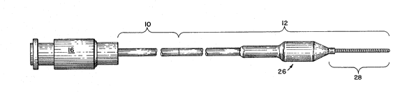
FIG. 1 illustrates the catheter which has a
proximal end (at the left in the drawing) and a
distal end (at the right in the drawing). The
catheter has a relatively long proximal segmen~ 10
which may be formed from narrow, solid wall tubing,
such as hypodermic tubing. In the illustrative
embodiment, the proximal segment 10 may be of the
order of 150 cm long. In the illustrative
embodiment, the proximal segment 10 may be rigid
torsionally so that it can transmit rotation from
its proximal to its distal end. The distal end
preferably can be bent to a curve so that the device
may be steered and directed as it is advanced
through the patient's vasculature. The proximal
segment 10 also is flexible and can bend
longitudinally to follow the curvature of the
patient's arterial system. Preferably, the proximal
segment 10 of the catheter is sufficiently flexible
so that it can bend to follow the curve of a
patient's aortic arch which has a radius of the
order of between 2.5 and 3.5 inches in an adult.
As shown more clearly in enlarged FIG. 4, in the
preferred embodiment of the invention the hollow
tubular proximal segment 10 may have an outer
diameter of 0.018", a wall thickness of about 0.002"
.
,
,:
B0410/7049
AZB/dmc 1 71 ~
04/07/88 ~ J ~) J L
9126B/7lB
and an internal diameter passage 14 of 0.014". A
conventional fitting 16 is attached to the proximal
end of segment 10 to facilitate connection with an
inflation/deflation device, such as a syringe (not
shown).
The catheter includes a distal segment 12 which
extends from the distal end of the proximal segment
10 to the distal end of the catheter. The distal
segment 12 includes a narrow diameter elongate
support wire 18 which is connected to and extends
distally of the tubular proximal segment 10. The
support wire 18 is connected to the proximal tubing
10 by a short transition tube 20. The transition
tube 20 is about 3" long and also is formed from a
slender, flexible hypodermic tubing with a smaller
diameter than the proximal tube 10. In the
illustrative embodiment, the transition tube 20 is
formed from hypodermic tubing having an outer
diameter of 0.014", a wall thickness of 0.003" and
an inner diameter of 0.008". The proximal end of
the tubing 20 is received within the distal end of
the internal passage 14 of the proximal segment 10
and is secured thereto as by soldering or brazing.
The solid support wire 18 is attached to the distal
end of the transition tube 20. The wire 18, which
in the illustrative embodiment is very slender,
preferably 0.008" diameter, is received in the
.
.~ , ~.. ~ . . .
.~ ~
Bo410/7049
AZ /dmc 1 3 1 5 6 3 2
9126B/7lB
distal end of the passage 2~ of the tubing 20 and is
secured by soldering or brazing. The support wire
18 plugs the distal end of the tubing 20. The
transition tube 20 is provided with apertures 24 on
opposite sides of the tubed wall to provide
communication with internal passages 22, 14 so as to
provide communication with a balloon 26 moun~ed on
the dis~al region of the catheter. The apertures 24
may be defined by forming a pair of longitudinal
slots in the wall of the tubing 20.
The support wire 18 provides support for the
balloon 26 and also extends distally beyond the
balloon 26, to form the core of a leader segment
28. The leader segment includes a helically wound
radiopaque coil spring 30 which is attached to the
distal end of the core wire 18 as described below.
The balloon 26 is formed by molding a high strength
polymeric material in a manner which provides a thin
balloon wall, not greater than about 0.001"
thickness and preferably having a thickness of the
order of 0.0005". The balloon may be manufactured
as described in U.S. Patent 4,490,421 issued
December 2$, 1984 and reference is made thereto for
further details concerning the manufacture of the
balloon.
As shown in enlarged detail in FIG. 6, the
balloon 26 is of a stepped configuration having a
proximal section 32 that is of smaller diameter than
- .
B0410/7049
AZB/dmc
04/07/88 1 31 5632
9126B/71B
a distal section 34. Both sections 32, 34 are
cylindrical and are joined by a proximally tapering
generally conical portion 36. By way of
illustrative example, the balloon may have an
overall length of about 25 mm, with the proximal
segment being approximately 12 to 13 mm in length
and about 2.0 mm in diameter and the distal segmert
being approximately 12 to 13 mm in length and 2.5 mm
in diameter. The balloon is formed from a high
strength material which will not tend to stretch
when inflated. For example, polyethylene
terepthalate is a desirable material for the
balloon. The balloon is formed to include tapering
portions 38, 40 at the proximal and distal ends
respectively. The distal tapering portion 40 merges
into a narrowed neck 42 which fits snugly about and
against the proximal end of the coil spring 30. The
distal neck 42 of the balloon 26 is adhesively
at~ached to the coil spring 30. The proximal end of
the coil spring 30 is soldered securely to the core
wire 18 at the region where the distal neck 42 is
joined. The proximal tapering portion 38 merges
into a narrowed proximal neck 44.
In order to communicate the interior of the
balloon 26 with the inflation/deflation passages 14,
22 of the tubing, an ex~ension sleeve 46 is
adhesively attached to the proximal neck ~4. The
4~ ~ :
' ~ :
,
B0410/7049
AZB/dmc8 1 31 5632
9126B/7lB
extension sleeve 46 extends proximally over the
support wire 18. The proximal end of the extension
sleeve 46 preferably is formed from the same
material as the balloon 26 and is securely and
adhesively attached to the outer surface of the
transition tube 20, where it joins the main tube
10. The extension sleeve 46 ~efines an annular
passage 48 about the support wire 1%. The annular
passage 48 provides communica~ion between the
apertures 24 and the interior of the balloon 26 for
inflation and deflation of the balloon.
As shown in FIG. 6, the leader segment 28 which
extends distally of the balloon 26 is of increasing
flexibility in a distal direction to provide a
relatively soft flexible leading tip which reduces
the chance of trauma or injury ~o the blood vessel.
In the illustrative embodiment, the leader segment
may be about 3 cm long. The coil spring 33 is
soldered at its proximal end, to the support wire 18
as indicated at 50. The distal end of the support
wire 18 also is soldered to the coil spring 30 as
indicated at 52. Soldered joint 52 and the distal
tip 54 of the support wire 18 terminate short of the
distal tip 56 of the coil spring 30. The distal
segment 58 of the coil spring 30 may extend about
5 mm beyond the soldered joint 52 and defines a
highly flexible bumper tip. A rounded weld bead 56
..~ ... .,, ~, . . .
.
.
B0410/7049
AZB/dmc 1 ~1 ~ 6 ~ ~
04/07/88 I J I J J
91~6B/71B
-- 10 --
formæ and defines the distal tip of the spring 30.
The leader segment 28 is of increasing flexibility
in a distal direction. The support wire 18 is taper
ground and, for example, may be ground smoothly to a
0.002" diameter at its distal tip 54.
The distal segment 58 of the coil spring 30
includes a flexible and bendable stainless steel
shaping ribbon 60 which is secured to the distal tip
54 of the support wire at one end and to the distal
weld bead 56 at its other end. The shaping ribbon
is of slender, rectangular cross-section, of the
order of 0.001" by 0.002". The shaping ribbon is
adapted to be bent to a desired curve and to retain
that curve when relaxed. The preset curve enables
the catheter to be steered by rotation of the
catheter from its proximal end to direct the bent
distal tip in selective directions as desired within
the patient's blood vessels.
The catheter also may be provided with a
radiopague marker band 62 which preferably is formed
from platinum. The marker band 62 is located
proximally of the main portion of the balloon 26.
In the illustrative embodiment, it is securely
attached to the support wire 18. The marker band 62
~S provides a means by which the physician can verify,
fluoroscopically, the position of the catheter.
.
. ~ ': ' . '
.:
'
:
B0410/7049 7
AZB/dmc 1 ~ 1 5 6 32
~*/07/88
9126B/718
FIG. 2 illustrates the kissing balloon technique
using conventional balloon catheters. FIG. 3
illustrates the manner in which the balloon
dilatation catheter of the present invention is used
in the kissing balloon technique. As shown
diagrammatically in each of FIGS. 2 and 3, a
bifurcated blood vessel has a trunk portion 64 and a
pair of bifurcated blood vessels 66, 68 in
communication with the trunk 64. The blood vessel
68 has a stenosis 70 ad~acent the junction of the
blood vessels. As is common, the stenosis may
extend partially around the bifurcation and into the
other blood vessel. In the kissing balloon
technique illustrated in FIG. 2, a pair of balloon
dilatation catheters are inserted through the trunk
vessel 64 with one of the balloons ~eing disposed in
each of the vessels 66, 68. The proximal ends of
the balloons typically remain in the trunk vessel 64
and contact or "kiss" each other. As illustrated in
FIG. 2, when the balloons are inflated, that may
tend to risk injury to the trunk vessel 64 from over
inflation. As illustrated in FIG. 3, with the
present invention, the proximal smaller diameter
portions of the balloon are disposed in the trunk
and will not over distend the trunk vessel 64.
It should be understood that although the
invention has been illustrated in FIG. 3 utilizing
. '
-
. ~ , ~.
B0410/7049 1 31 S 6 32
04~07/88
9126B/7lB
- 12 -
two catheters of the present invention, the
invention also may be practiced using a conventional
balloon dilatation catheter together with one
catheter having a balloon with a reduced proximal
diameter in accordance with the invention, depending
on the coronary anatomy of the particular patient.
Thus, the invention provides a dilatation
catheter configuration adapated specifically for
reduced risk in the practice of the kissing balloon
technique. It should be understood that the
foregoing description of the invention is intended
to be illustrative thereof and that other
embodiments and modifications may be apparent to
those skilled in the art.
Having thus described the invention, what I
desire to claim and secure by letters patent is:
, : :
.
.. .
.
.
:. .
:. . , - ~ . .