Language selection

Search

Patent 1322910 Summary

Third-party information liability

Some of the information on this Web page has been provided by external sources. The Government of Canada is not responsible for the accuracy, reliability or currency of the information supplied by external sources. Users wishing to rely upon this information should consult directly with the source of the information. Content provided by external sources is not subject to official languages, privacy and accessibility requirements.

Claims and Abstract availability

Any discrepancies in the text and image of the Claims and Abstract are due to differing posting times. Text of the Claims and Abstract are posted:

  • At the time the application is open to public inspection;
  • At the time of issue of the patent (grant).
(12) Patent: (11) CA 1322910
(21) Application Number: 577246
(54) English Title: DEVICE FOR PREVENTING INVOLUNTARY MICTURITION
(54) French Title: DISPOSITIF POUR PREVENIR LA MICTION INVOLONTAIRE
Status: Deemed expired
Bibliographic Data
(52) Canadian Patent Classification (CPC):
  • 128/36
(51) International Patent Classification (IPC):
  • A61F 5/455 (2006.01)
  • A61F 2/00 (2006.01)
(72) Inventors :
  • JONASSON, LINDA (Denmark)
(73) Owners :
  • JONASSON, LINDA (Denmark)
(71) Applicants :
(74) Agent: MACRAE & CO.
(74) Associate agent:
(45) Issued: 1993-10-12
(22) Filed Date: 1988-09-13
Availability of licence: N/A
(25) Language of filing: English

Patent Cooperation Treaty (PCT): No

(30) Application Priority Data:
Application No. Country/Territory Date
4840/87 Denmark 1987-09-15

Abstracts

English Abstract


Abstract:

A device for preventing involuntary micturition, preferably
in human females, comprises an oblong, comparatively thin
shaft (1). This shaft (1) carries at least one knob (2,
3, 4) forming a thickening on the shaft (1) and being
arranged at a distance from the proximal end of the shaft
(1). The proximal end of the shaft (1) is provided with a
comparatively thin, transverse flap (5).


Claims

Note: Claims are shown in the official language in which they were submitted.


THE EMBODIMENTS OF THE INVENTION IN WHICH AN EXCLUSIVE
PROPERTY OR PRIVILEGE IS CLAIMED ARE DEFINED AS
FOLLOWS:
1. A device for preventing involuntary
micturition, preferably in human females, comprising a
substantially solid oblong; substantially form-stable
flexible body with varying cross-sectional area
depending on the distance from an end of the body and
providing at least one knob forming a thickening
arranged at a distance from a first end of the body,
said knob sized to pass into the urethra and to retain
the device in the urethra, and that the first end of
the oblong body is provided with a comparatively thin,
transverse flap, extending perpendicular to the axis of
the body.

2. A device as claimed in claim 1, characterized
in that the oblong body is a shaft (1) having three
mutually spaced knobs (2, 3, 4).

3. A device as claimed in claim 1, characterized
in that the knob or knobs ( 2, 3, 4) are of a
substantially ellipsoid shape.

4. A device as claimed in claim 1, characterized
in that the thin, transverse flap (5) has the shape of
an annular disc.

5. A device as claimed in claim 1, characterized
in that it is made in form of one integral part of a
plastic material.

6. A device as claimed in claim 1, characterized
in that the body (1) is provided with a cavity (6) with
an opening at the flap (5).


7. A device for preventing involuntary
micturition, comprising a thin shaft having a first
end, a second end and a closed-ended cavity, said shaft
having three mutually spaced, ellipsoidal knobs
arranged near the second end, said knobs being sized to
pass into the urethra and to retain the device in the
urethra, said cavity having an opening at said first
end to receive an insertion means, said first end being
attached to a thin, transverse flap in the shape of an
annular disc, and said device being formed from a
single piece of soft plastic.

8. A micturition controlling device comprising:
means for preventing involuntary micturition,
said means comprising a closed shaft and having a first
end and a second end;
means for positioning the preventing means in
the urethra, said positioning means being located on
the preventing means near the second end, said
positioning means shaped and situated to cooperate with
urethral muscles, said positioning means being sized to
pass into the urethra and to retain the device in the
urethra; and
means for facilitating withdrawing the
preventing means, said facilitating means being
attached to the first end of the preventing means, said
facilitating means further preventing the device being
too deeply inserted into the urethra.

9. A device as in claim 8, wherein said
preventing means comprises a shaft of variable
diameter.

10. A device as in claim 9, wherein said shaft
comprises at least one knob which is located near the
second end of the shaft and which facilitates


positioning of the device within the urethra.

11. A device as in claim 10, wherein said knob is
of a substantially ellipsoidal shape.

12. A device as in claim 9, wherein said shaft
comprises three mutually spaced knobs, which are
located near the second end of the shaft and which
facilitate positioning of the device within the
urethra.

13. A device as in claim 8, wherein said
facilitating means comprises a transverse flap.

14. A device as in claim 13, wherein said
transverse flap has the shape of a thin, annular disc.

15. A device as in claim 8, further comprising
means for insertion, said insertion means comprising a
cavity in said shaft having an opening at the first end
of the shaft and a means for filling the cavity.

16. A device as in claim 15, wherein said filling
means is a long, thin pin.

17. A device as in claim 8, wherein said device
is made of one integral piece of soft plastic.

18. A device for preventing involuntary
micturition comprising:
a substantially solid shaft of variable
diameter for preventing micturition, said shaft having
a first end and a second end;
at least one knob for positioning the shaft
in the urethra, said knob being located on the shaft
near its second end, said knob being shaped and


situated to cooperate with urethral muscles, and said
knob being sized to pass into the urethra and to retain
the device in the urethra;
a transverse flap for facilitating
withdrawing the shaft, said flap being attached to the
first end of the shaft, said flap further preventing
the device being too deeply inserted into the urethra.

19. A device as in claim 18, wherein at least one
knob comprises three mutually spaced knobs.

20. A device as in claim 18, wherein said knob is
of a substantially ellipsoidal shape.

21. A device as in claim 18, wherein said
transverse flap has the shape of a thin, annular disc.

22. A device as in claim 18, wherein the shaft,
knob, and transverse flap are made of one integral
piece of soft plastic.

23. A device as in claim 18, further comprising a
pin for insertion, said pin being inserted into a
cavity with an opening at the first end of the shaft.

Description

Note: Descriptions are shown in the official language in which they were submitted.


1 3229 1 0

Title: A device for preventing involuntarv micturition

Technical Field

5 The present invention relates to a device for preventing
involuntary micturition, preferably in human females.

Background Art

10 Numerous devices for preventing involuntary micturition
in human females are known. Such devices include for
instance a device inserted in the urethra by means of a
special instrument, said device expanding in the urethra
when the instrument is removed. Such devices are usually
15 difficult to manipulate and irritate a patient during
use.

Disclosure of the Invention

20 The object of the present invention is to provide a device
easy to insert and causing no irritation to a patient
carrying the device.

The object of the invention is accomplished by a device
25 comprising an oblong, substantially form-stable body with
varying cross-sectional diameter, the proximal end of the
oblong body being provided with a comparatively thin,
transverse flap.

30 As a result the inventive device is easily inserted in
the urethra and has shown itself to be unproblematic during
use. Moreover the device is easily removable, since it
can be pressed out by the user during voluntary micturi-
tion. Optionally it can also be withdrawn by holding on
35 to the flap at the proximal end. The flap acts also as a
safeguard against the device being too deeply inserted in
the urethra.
~`

1 3229 1 0


According to the invention the oblong body is a
comparatively thin shaft carrying at least one knob
forming thickenings on the shaft and being arranged at
a distance from the proximal end of the shaft. This
embodiment of the inventive device is of special
advantage with respect to prevention of involuntary
micturition. This is predominantly due to its tendency
to position itself in such a way that the knobs are
located within the strongest sections of the urethral
muscles, thus increasing the sphincteral pressure of
the urethra.

In an especially preferred embodiment the shaft
comprises three mutually spaced knobs.

In accordance with the invention the knob or knobs can
be of ellipsoid shape thus achieving an especially
gentle and well-functioning co-operation with the
surrounding urethral tissue and muscles.

Further in accordance with the invention, the thin,
transverse flap can have the form of an annular disc.
Thus the inventive device is easy to manipulate during
the insertion and the optional withdrawal.

In accordance with another aspect of the invention, a
method for controlling involuntary micturition is
contemplated by providing an elongated shaft having
first and second ends, a transverse flap attached to
the first end, and at least one knob located on the
shaft near the second end. The knob is of sufficient
size such that it can pass into the urethra and may be


sd/lcd

-

1 3229 ~ O
2A

retained therein. By grasping the first end, the
second end can be inserted into the urethra and left
therein until micturition is to be performed whereupon
the shaft may be removed from the urethra to empty the
bladder.
Brief Description of the Drawings

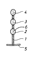
Fig. 1 is a side view of an especially suitable
embodiment of an inventive device, and

Fig. 2 is a graphic representation of the pressure in
the urethra of a person with a normally functioning
urethra, and of a patient suffering from urinary
incontinence.
Best Mode for Carrying Out the Invention

The device of Fig. 1 comprises an oblong body in form
of


sd/lcd
'~

t~2~tO


a comparatively thin shaft 1 with three mutually spaced
ellipsoid knobs 2, 3 and 4, the knob 4 being at the distal
end of the shaft, said end being placed furthest inside
the urethra during use. The proximal end of the shaft 1
5 is provided with a thin disc 5.

In a preferred embodiment the device is of a length of
approx. 5 cm, and the shaft 1 is of annular cross-section
with a diameter of approx. 2 mm. The knobs 2, 3 and 4
10 have a mutual distance of approx. 4 mm and their largest
diameter measured perpendicular to the shaft is approx. 7
mm. The length of the knobs 2, 3 and 4 is approx. 8 mm,
measured in the longitudinal direction of the shaft. The
annular disc 5 is of a diameter of approx. 14 mm and of a
15 thickness of less than 0.5 mm. The entire device is suit-
ably integrally made of a comparatively soft plastic
material having such a rigidity that it is easily inserted
in the urethra. The shaft is optionally hollow to receive
an insertion means in form of a long, thin pin. The plastic
20 material is preferably tissue-compatible and desinfecting.

The urethra of an adult human female is usually of a length
of 3-5 cm and surrounded by muscles over its entire length
from the bladder to the external urethral ostium. The
25 strongest muscles of this muscle group are situated
adjacent the bladder as well as in the middle of the
urethra. These muscles usually seal off the urethra. A
graphic representation of the pressure maintaining a sealed
urethra in a human female usually follows a curve depicted
30 at I in Fig. 2. The abscissa indicates the length of the
urethra measured from the bladder to the external urethral
ostium (M), and the ordinate indicates the pressure
measured in Pa. Usually the pressure in the urethra is
approx. 600 - 700 Pa. The intravesical pressure of a person
35 standing upright is normally between 300 and 400 Pa, as
indicated by means of curve II in Fig. 2. Thus the normal
safety margin is approx. 400 Pa over the entire length of

t 3229 1 0


the urethra. Curve III of Fig.2 shows a pressure distribu-
tion for-the urethra of a patient suffering from incon-
tinence. As is apparent, only a short part of the urethra,
i.e. approx. 5 mm, is subjected to a sphincteral pressure
5 higher than the intravesical pressure.

The device of Fig. 1 was tested with the patient on which
the pressure distribution of curve III, Fig. 2, was
measured. Prior to insertion of the device the ability of
10 the urethra to retain liquids was tested. The bladder was
filled with 300 ml water (75% filled), whereupon the person
was asked to take the elevator up to the next floor and
return via the staircase. This trip was repeated twice.
During the experiment the person lost the 300 ml water and
15 additionally approx. 50-100 ml liquid produced during the
experiment.

The experiment was then repeated with the device of Fig.
1 inserted in the urethra. During this experiment the
20 person lost only approx. 15 ml.

An examination of the position of the device in the urethra
revealed that the knob 2 closest to the disc 5 was about
in the middle of the urethra, i.e. within the area where
25 the sphincteral pressure is highest, while the two
following knobs were positioned in the vesical ostium and
inside the bladder, respectively. It cannot be excluded
that the two latter knobs had some effect with respect to
retaining liquid, but the presence of three knobs 2, 3
30 and 4 allows the device to obtain a better position with
respect to the muscles of the urinary tract compared to a
device with only one knob. By measuring the pressure in
the urethra of a patient suffering from incontinence it is
apparent where the muscles are strongest, thus permitting
35 the selection of the device best corresponding to the needs
of the patient in question. In such a case the distances
between the knobs and the annular disc 5 may differ from

1322910


the ones above.

The above experiment was repeated with other patients, i.a.
also with men, and had the same promising results.


A special characteristic of the inventive device is that
it turned out to act as a stimulant to the urethral
muscles. Experiments have shown that these muscles dis-
played a temporary increase in strength after use of the
10 inventive device.

The invention is described with respect to a preferred
embodiment. Many alterations can, however, be made without
thereby deviating from the scope of the invention. The
15 knobs can be of a shape other than ellipsoid. The annular
disc can be replaced by a small strip projecting to one
side with respect to the shaft. The device can, if so
desired, be provided with a cavity (6) as to increase
its flexibility. This cavity can for instance open out-
20 wardly at the end where the annular disc is located. Insuch a case the inventive device can be inserted by means
of a stiff, oblong means (not shown) inserted in the cavity
(6) and removed after the inventive device has been posi-
tioned in the urethra. The number of knobs can, if desired,
25 also differ from the one shown. Instead of a thin shaft
with knobs the oblong body can be of larger diameter and
provided with a number of recesses.

Representative Drawing
A single figure which represents the drawing illustrating the invention.
Administrative Status

For a clearer understanding of the status of the application/patent presented on this page, the site Disclaimer , as well as the definitions for Patent , Administrative Status , Maintenance Fee  and Payment History  should be consulted.

Administrative Status

Title Date
Forecasted Issue Date 1993-10-12
(22) Filed 1988-09-13
(45) Issued 1993-10-12
Deemed Expired 1999-10-12

Abandonment History

There is no abandonment history.

Payment History

Fee Type Anniversary Year Due Date Amount Paid Paid Date
Application Fee $0.00 1988-09-13
Maintenance Fee - Patent - Old Act 2 1995-10-12 $50.00 1995-10-11
Maintenance Fee - Patent - Old Act 3 1996-10-14 $50.00 1996-10-09
Maintenance Fee - Patent - Old Act 4 1997-10-14 $50.00 1997-10-07
Owners on Record

Note: Records showing the ownership history in alphabetical order.

Current Owners on Record
JONASSON, LINDA
Past Owners on Record
None
Past Owners that do not appear in the "Owners on Record" listing will appear in other documentation within the application.
Documents

To view selected files, please enter reCAPTCHA code :


To view images, click a link in the Document Description column. To download the documents, select one or more checkboxes in the first column and then click the "Download Selected in PDF format (Zip Archive)" or the "Download Selected as Single PDF" button.

List of published and non-published patent-specific documents on the CPD .

If you have any difficulty accessing content, you can call the Client Service Centre at 1-866-997-1936 or send them an e-mail at CIPO Client Service Centre.


Document
Description 
Date
(yyyy-mm-dd) 
Number of pages   Size of Image (KB) 
Drawings 1994-03-08 1 7
Claims 1994-03-08 4 116
Abstract 1994-03-08 1 9
Cover Page 1994-03-08 1 12
Description 1994-03-08 6 186
Representative Drawing 2000-08-17 1 2
Prosecution Correspondence 1993-04-08 1 33
Examiner Requisition 1993-02-26 1 89
Prosecution Correspondence 1993-01-29 2 46
Examiner Requisition 1992-11-09 1 75
Prosecution Correspondence 1991-03-07 4 153
Examiner Requisition 1990-12-10 1 64
PCT Correspondence 1993-07-07 2 50
Fees 1996-10-09 1 37
Fees 1995-10-11 1 43