Note: Descriptions are shown in the official language in which they were submitted.
F.N. 44008 CAN 7A
-1- 1329242
; A TERMINATION MODULE FOR USE IN AN ARRAY OF MODULES
Background of the Invention
1. Field of the Invention
The present invention relates to a termination
module for use in an array of modules for terminating
transmission lines and in one aspect to a panel for
supporting a plurality of modules to be connected to said
transmission lines, i.e. optical fibers, copper, aluminum
or other conductors, so they can be readily connected to
distribution lined leading to opto-electronic or
electronic equipment.
2. Description o;f the Prior Art
The present invention provides a module for
connection to the common transmission wires entering a
residence or factory or office work station where it is
desired to have the service positioned in one spot. This
requirement places a plurality of wires in close spaced
relationship and it is desirable not to use a lot of
space but provide easy access to the transmission lines
for connection and disconnection of the distribution
cables.
The prior art has a variety of panel
configurations for connecting the lines in an incoming
cable to the connectors and managing the connection of
the lines to distribution lines. Such panels are
provided for optical fibers, electrical power
distribution, and telephone distribution. The present
invention provides a module and panel wherein a plurality
of modules can be closely positioned to provide
termination of the cables for connection to the cables
provided on electronic equipment such as opto-electronic
equipment or on electronic equipment such as stereo
receivers, television sets, telephones and computer work
stations.
The present invention is directed at a
' 3~
.
- ~
;.
-
1329242
-2-
simplified array of modules for use in terminating a
small number of optical fibers, or fibers and
transmission wires such as in an apartment building,
a single family residence, or an office or factory work
station. The prior art panels in some instances may be
modular to afford their use with a small number of fibers
but they are adapted to the large termination situations
where many fibers or wires are terminated and the panels
can be enlarged as the service needed increases. In the
present environment it is necessary that the distribution
lines be terminated in such a way that they can be
connected and disconnected without calling a skilled
technician. There are generally only a small number of
lines and they should be conveniently packaged to permit
a person with minimal assembly skills to make the
connections and disconnections to the transmission lines
coming into panel. A skilled technician will generally
make the connection from the incoming line to the panel
connector and then the minimally skilled assembler can
make the connection to the panel connector. The
connector usually includes a convenient connection to
which a plug may then be readily connected to couple the
incoming line to the desired equipment.
With optical fiber installations, the
technicians,are the workers with the responsibility of
taking the optical fiber cable that has arrived at the
termination station and separating the individual optical
fibers from a buffer tube and then splicing them to a
fiber end leading from a connector plug. The plugs are
subsequently connected to a connector coupling for
connection to a plug on a fiber running to an opto-
electronic piece of equipment. When this piece of
equipment is a piece of equipment in a home, factory or
office work station and the number of optical fibers
directed thereto are all contained in a single cable, or
the cable contains optical fibers together with copper
signal wires, it is desirable to have a convenient means
.~,
1329242
3--
of termination of the optical ~ibers as well as a
convenient method of joining the copper wires to a
distribution wire. This type of termination should not
require any more skill than the technician that would
routinely service and install telephone or electrical
power. If it requires tools that cut and polish the
optical fiber end and special fixtures to secure the
finished fiber end in a plug, then the level of skill
required to make only several connections at remote
locations is economically and commercially disadvantaged,
and the optical fiber communication system will not grow
,.
`~ and be as readily available to as many citizens as
rapidly as desired.
Presently, where large installations are made
in a building or central station, a distribution housing
; is installed and the cable is brought in for
distribution. Individual optical fibers from the cable
are spliced to long pigtails, each consisting of
individually jacketed optical fiber terminated into a
connector plug at one end. The pigtail connector plug is
mounted into a connector coupling located within the
distribution housing or a remote second distribution
housing. The splice joining the two fibers is placed
within a splice holder within the first distribution
housing. The surplus fiber from the pigtail and surplus
fiber from the cable are both carefully stored in the
distribution housing. A second plug mates with the first
in the connector coupling and routes to an opto-
electronic device or other intermediate junction. This
is the routine which must be followed in tpe large
installations since it is very possible that changes will
be needed periodically and access to the splice and the
slack fiber will be required. In the home, apartment or
factory or office work station on the other hand, the
connection will be made and there should be no need for a
large distribution panel or box. The termination and its
support and the support for the additional slack fiber
1329242
~ 4 60557-3757
:
- should not exceed that same requlrement for copper communlcatlon
llnes.
.-~, A prlor devlce, ldentlfled as an optlcal cable header ls
~, descrlbed ln U.S.A. patent No. 4,585,303. Thls devlce utlllzes a
~i plurallty of optlcal connector supports whlch are engaged ln a
`~ magazlne or houslng. The connector supports have an elongate body
,: ~t
' in the form of a hollow flnger. The flnger has a cyllndrical con-
. . ,
nector member at a front end and a slde mounted former upon whlch
to wlnd a length of flber located near to lts opposlte or rear
end. The magazlne has a row of cavltle3 whlch are open at the
.;
rear of the magazlne for recelvlng the supports and have clrcular
openlngs ln the front wall to recelve the connector members on the
connector supports when they are recelved ln the cavltles. In
Figures 7 - 11 of U.S. Patent No. 4,585,303 the optlcal connector
support ls shown to lnclude a flnger, constltuted by a rlgld metal
blade formed of elongate U shape. The optlcal connector ls mount-
ed ln the bottom of the U to recelve the end flttlng of a flber
lnslde the flnger. The optlcal connector wlll also recelve an
analogous end flttlng of an external flber for connectlon to the
flber lnslde the flnger. The connector descrlbed ln the lntroduc-
tlon ls an lnstalled connectlon end flttlng, for example the one
descrlbed ln French patent 2 275 787 and patent of addltlon 2 316
611, the earllest patent correspondlng generally to U.S.A. patent
Nos. 3,989,567 and 4,050,783. Thls connector ls deslgned to re-
celve one or multlple flbers, but to recelve one flber, requlres
an lnstallatlon and ln each end flttlng, the end face of a flber
'''
, "
~'
. , :
`-- 1329242
4a 60557-3757
ls rectlfled and sultably posltloned for provldlng accurate optl-
cal connectlon when two connectlon flttlngs are brought together.
The lnstallatlon of the end fittlng is not perceived as a fleld
installation slnce patent No. 4,585,303 refers to the cable having
, a plurality of optlcal fibers wlth each flber havlng a connectlon
.~ end fltting installed on lts end. The purpose of the
'
- ~ :
" :
, :
1329242
-5-
patented header is to avoid having to interrupt the
connection of several fibers as with the connector of
patent No. 4,050,783, when repairing a defect in the
connection between any one pair of fibers. Further,
after the supports are placed in the magazine, the
connector members on the front face of the magazine are
` aligned in fixed position in a row and are not readily or
individually accessible to make the desired connections.
Another mounting panel with means for
supporting a plurality of connectors is shown in U.S.A.
patent No. 4,752,110. This patent shows a cabinet for
supporting incoming fibers, slack in those fibers,
splices, connectors and pigtail fibers, and the plugs for
the distribution fibers. This is typical of the prior
art and is too bulky and unnecessarily complicated to
provide the termination in the residence or apartment
building. It is therefore an object of this invention to
provide a termination which will reduce the need for
large or bulky boxes to handle incoming and connector
fibers to afford the installation of optical fibers into
~; a residence and connection of the incoming optical fibers
to opto-electronic equipment.
Previous methods of gaining finger access room
to tightly spaced connectors have relied on the ability
of wire and coaxial cable connections to sustain tight
radius curva~ture and even right angle bends. This
ability has allowed designers of connector arrays for
electrical conductors to have close clearance in the
design of the array through sudden changes in the axis of
conductors, and no penalty is incurred by inducing tight
bends into the conductors when con~ections are moved to
obtain access.
Electrical connector groupings are also
forgiving of movement of jumper wires and connections,
since disturbing the connected wires has negligible
effect upon signal continuity or transmission.
This is in contrast with optical fiber
,: .
1329242
--6--
connections, where the fibers are typically restricted to
a bend radius on the order of 20 or more times the outer
diameter of the fiber and its jacket. Additionally,
movement of optical fiber connections and cables can
produce temporary or even permanent loss or reduction in
signal carrying ability, due to unintended bending of
fibers adjacent to a fiber being connected or removed.
As a result, the schemes which obtain
electrical connector access in a tight array, such as
through a push-pull action along the axis of the
connection, are inappropriate for optical fiber work.
The subject action of a slight tilt of the fiber axis is
especially apt in that the bend of the fiber which is
induced is not only of wide radius, but also the degree
of bend is limited to a small arc, and the exiting fiber
is subjected to only the minimal translation upwards
which will provide access. If translation along the
fiber were involved, in most installations, severe
problems with bend radius kinks would result along the
axis of the fiber. The method in which both of these
factors are addressed here can be relied upon to
contribute a negligible harm to the transmission
properties of the fiber being worked on, and also give a
negligible effect to adjacent fibers.
Although these minimal-disruption features are
not crucially important in electrical connections, they
are nevertheless desirable for connection of coaxial
cables and other conductors where cable diameters
restrict conductor bending, and in any event comprise a
useful and versatile system where it is desired to
connect optical fibers and electrical cables in a single
- housing, or to standardize on a single termination type
for a distribution location or system. Frequently,
optical fiber cables will also incorporate one or more
"talk pairs" or "order pairs" to allow craft persons to
communicate during installation or maintenance, or to
provide power to run ringing bells, warning lights, and
1329242
-7-
other associated electrical devices on what is primarily
an optical transmission syste~. Hybrid systems with
paired wire, coaxial cable and optical fiber for
broadband communications are also seen, and a system
which can terminate all types of communication media with
interchangeable plug-in units has versatility in addition
to functional benefits with any one of the media it
accommodates.
It is a further ob;ect of the present invention
; 10 to provide a module which can be packaged in an array
wherein the modules are in side-by-side relationship to
-~ fit in a compact panel, in an array with other modules, in such a manner as to afford ready access to the
individual connectors for attachment of the distribution
fibers or other lines.
Summarv of the Invention
The present invention provides a novel
termination module for use in terminating a cabled
optical fiber or other transmission cable at a connector
~0 to which connection can readily be made by a ubiquitous
type of plug such as a phono-type plug on coaxial cable,
optical fiber plug, the RJ-ll plug on a telephone cable
or the pin plug for an antenna or cable connection. The
module is particularly adapted to terminate the
individual transmission lines and to mate with other
modules to provide a compact array of modules, each
having a connector as readily accessible when reguired as
a single module.
~~ The module comprises a frame for supporting a
single connector plug supported at one end of the frame
and connected to one end of a transmission line. The
frame has a generally tubular profile, including a
generally rectangular base extending from the aforesaid
end of the frame. The base is generally rectangular with
a ~ongitudinal axis and is provided with means for
tilting the base about an axis transverse to the
longitudinal axis and intermediate its ends such that the
- --
, .
,
; 1329242
8 60557-3757
one end of the frame may be ralsed from the normal plane of the
base to a positlon above the ends of the other modules ln a slde-
by-slde array. Thls type of module avolds the need to space the
modules or the connectors to afford ready access to the connectors
to connect or dlsconnect a dlstributlon llne to the connector.
The means for tlltlng the ba6e about an axis transverse to the
axls of the base lncludes a fulcrum about whlch the base can be
rocked or the base can rock on a rocker which will allow the one
end to rlse above the other ends of the ad~acent modules. The
modules are preferably mounted for tiltlng movement about a common
axls so they malntaln allgnment or they are otherwlse located to
malntain a normally flxed position.
Means are provided for restricting movement of the
modules when in the normal position. The modules can be moved to
the connect position against the resistance of the stop, detent or
spring used to retain the module. The axis for mounting the
modules is formed in the bottom of a shallow tray and modules are
; arranged ln a side-by-side array. Means ls provlded ln the tray
for storlng slack flber from the transmlsslon llne. The storage
area ls preferably provlded wlth a cover to llmlt access thereto
because after the technlclan has made the connectlon to the
connector the remainlng connectlons are made to the coupllngs and
such can be made by ralslng the coupllng from the plane of the
other coupllngs and have free sccess to the coupllng deslred.
The lnventlon may be summarlzed, accordlng to one
, aspect, as a module for use ln termlnatlng a communlcatlon
transmlsslon llne at a dlstrlbutlon panel comprlslng a connector
, adapted to be connected to one end of a transmlssion llne, and
support means for supportlng sald connector, sald Yupport means
comprlslng an end wall supporting sald connector ln flxed posltlon
thereon and a rectangular base ~olned to sald end wall and
extendlng ln a dlrectlon away from sald end wall, sald base
comprlslng an elongate narrow strlp havlng a top surface and a
bottom surface, means deflnlng an axis transverse to sald bottom
surface for affordlng tlltlng movement of said base to move said
end wall from a flrst normal posltion to a spaced posltion for
affordlng ea3y access to sald connector, said means deflnlng sald
axls transverse to sald bottom surface comprlses a recess spaced
.. . .
~ 1329242
8a 60557-3757
from sald end wall for recelvlng a rod about whlch said base may
plvot, sald recess lncludlng an offset area for recelvlng a said
rod, and sald base lncludes a portlon extendlng away from sald
recess ln a dlrectlon opposlte sald end wall deflnlng stop means
for llmltlng sald tlltlng movement.
Accordlng to another aspect, the lnventlon provldes a
plurallty of transmlsslon llne terminatlon modules posltloned ln
slde-by-slde relatlonshlp, each module comprlslng a connector
adapted to be connected to one end of a transmlsslon llne, and
support means for supportlng sald connector, sald support means
comprlslng an end wall havlng two faces for supportlng sald
connector ln flxed posltlon thereon and a rectangular base ~olned
to sald end wall at one end thereof and extendlng ln a dlrectlon
:~ away from one face thereof, sald base lncludlng means deflnlng an
axls transverse to sald base for affordlng tlltlng movement of
sald base of each module to move sald end wall of each module
lndependently of the other modules from a flrst normal posltlon
allgned wlth the connectors of ad~acent modules to a spaced
posltlon ln relatlon~hlp to sald ad~acent connectors for affordlng
..~ 20 easy access to sald connector for connectlng or dlsconnectlng a
.. dlstrlbutlon llne wlth sald connector, and for returnlng sald
- modules to sald normal posltlon.
. Accordlng to a further aspect, the lnventlon provldes a
dlstrlbutlon panel for use ln connectlng transmlsslon llnes to
. 25 connectors affordlng further dlstrlbutlon, sald panel lncludlng a
support plate, sald support plate havlng a generally planar
surface and means for deflnlng a fulcrum, and a plurallty of
,i termlnatlon modules posltloned ln a slde-by-slde array on sald
: .
plate and supported on sald fulcrum for lndependent tlltlng
movement, each module comprlslng a connector adapted for
connectlon to a transmlsslon llne, and support means for
supportlng sald connector, sald support means comprlslng an end
- wall havlng four sldes and two faces for supportlng sald connector
ln flxed posltlon thereon, a base ~olned to one slde of sald end
, 35 wall and extendlng ln a dlrectlon away from one face thereof, sald
base lncludlng means affordlng tlltlng movement of sald module
: lndependently of ad~acent modules about sald fulcrum and ln
relatlonshlp to other modules to posltlon sald end wall of sald
; A
~,
.
~ .
1329242
8~ 60557-3757
module ln spaced relatlonshlp to the end wall of others of sald
modules ln sald array affording easy access to the connector for
: plugglng and unplugglng dlstrlbutlon llnes to sald connector and
returnlng the connector to a normal posltlon when the connectlon
ls completed.
Brlef DescriPtlon of the Drawlnq
The present lnventlon wlll be further descrlbed wlth
reference to the accompanylng drawlng whereln:
Flgure 1 18 a perspectlve vlew of an array of optlcal
flber termlnatlon modules accordlng to the present lnventlon ln a
slde-by-slde array1
Flgure 2 ls a perspectlve vlew of the module array of
- Flg. l wlth a slngle module tllt,ed to lllustrate easy access to
the connector,
,
' ' ' . :
.
1329242
_9_
Figure 3 is a perspective view of the array of
termination modules packaged i~ a tray-like panel adapted
to fit compactly in a cupboard or closet;
. Figure 4 is an exploded perspective view of an
optical fiber termination module illustrating the several
parts thereof:
Figure 5 is an exploded perspective view of a
module positioned above the support plate of the panel to
illustrate the mounting of the mod~le:
: 10 Figure 6 is a longitudinal sectional view of a
module on the support plate showing the module in the
normal position:
Figure 7 is a longitudinal sectional view
similar to that of Fig. 6 showing the module in the
tilted or raised position to afford easy access to the
connector;
Figure 8 is an exploded perspective view of a
~ second embodiment of a module and a support plate for the
:: module;
~. 20 Figure g is an exploded perspective view of a
`i, further embodiment of a module and a support plate for
the module;
~ Figure 10 is a perspective view of a further
: embodiment of a module and a support base for tilting
the module;
:' Figure 11 is an exploded perspective view of a
; further embodiment of a module and a support plate for
the module;
Figure 12 is a fragmentary perspective view of
a pair of modules in a side-by-side array with the
modules having two different types of couplers on the end
; wall;
. Figure 13 is a fragmentary perspective end view
of a module having a grommet in the end wall;
Figure 14 is a fragmentary perspective end view
of a module having an RJ-ll jack for a telephone plug
also illustrated in perspective; and
. '` ~,,"
: ~ .
1329242
--10--
Figure 15 is a fragmentary perspective end view
of a pair of modules in a side-by-side array with data,
television and phono-type coaxial connectors mounted in
the end walls of the modules.
Description of the Preferred Embodiments
The optical fiber termination splice module and
the array formed upon packaging of the same according to
the present invention will be described with reference to
the accompanying drawings wherein like parts are
identified by the same reference numerals throughout the
several views.
When connectors are placed in juxtaposition it
is often very difficult for a person to obtain proper
access to the connector for the purpose of coupling or
uncoupling a plug to a connector and not risk damage to
or contact with the other connectors. Therefore, the
present invention has as an object the provision of a
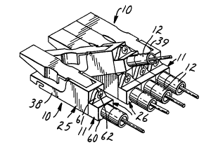
termination module 10 having a connector 11 thereon which
module 10 can be placed on the end of a signal conductor
and placed closely adjacent another module 10 terminating
a second signal conductor, but which affords the
separation of the connectors to afford facile coupling
and uncoupling thereto. As illustrated in Figures 1 and
` 2, the closely packed modules 10 do not allow access by
the fingers readily when it is desirable to couple or
` uncouple a plug 12 from a connector 11 when the modules
are arranged in side-by-side position. A module
according to the present invention allows the desired
module to be tilted, raising the connector from the side-
by-side location allowing ready access to the connector
as is shown in Figure 2.
The array of modules 10 are preferably
positioned in a tray 15 adapted for mounting in a
cupboard or closet such that the modules are kept in
order and conveniently, centrally located. The tray 15
is,a shallow rectangular tray with a base 16 and side
walls 17 which project upwardly from the base 16. One
. .
1329242
area on one end of the base is dedicated to receiving and
storing a length of the optical fibers. The tray side
walls 17 are provided with preperforated areas 18 which
can be removed to afford entry of the signal conductors
into the storage area. Additional knock-out areas 19
afford exit openings for the distribution fibers.
plurality of ears 20 are formed in the storage area about
which the conductors may be wrapped to form one or more
loops. As illustrated the conductors are wrapped on ears
20 which are formed from the base and positioned to
define a loop area at least twice the minimum bending
radius for an optical fiber of the incoming fiber buffer
tube 21. Thé individual fibers 22 are then directed from
the loop to the individual modules 10.
The module 10 illustrated in Figures 4, 5, 6,
and 7 comprises a small frame or support 25, the coupling
26 of the optical fiber connector 11, a single connector
:,
plug 28 connected to one end of a short length 29 of
` optical fiber and joined to one end of the coupling 26,
an optical fiber splice 30 having opposite open ends for
making connection between a second end of the length 29
: of optical fiber and the free end of the optical fiber 22
from a cable 21, as previously described.
The frame or support means 25 for supporting
the coupling 26 and the splice 30, comprise,s an end wall
32 having four sides and two faces 33 and 34, and an
opening therethrough for supporting the connector
coupling 26 in fixed position thereon and a base 35. The
base 35 is a narrow elongate strip molded integrally with
and joined to one side of the end wall 32 and the base 35
extends in a direction away from the face 33 of the end
wall 32. The frame or support means 25 also includes a
pair of side walls 38 and 39, and means defining a
magazine 40 for supporting the splice 30 in close spaced
relationship to the end wall 32, allowing space for
connection of the plug 28 into the coupling 26. The
magazine 40 is shaped to receive the splice 30 and to
13~9242
-12-
hold the same in a position aligned with the plug 28 to
receive, in the splice 30 at a position approximately
half the length of the splice, the second or free end of
the length 29 of optical fiber fixed in the plug 28. The
magazine 40 has wall members to receive and support the
splice in position to permit the splicing of an incoming
fiber with the length of fiber 29 to be completed. In
Figure 4 the magazine 40 is shown as a channel shaped
member, shaped to fit the shape of the splice 30 placed
therein.
In the illustrated magazine 40 a splice
according to U.S.A. patent No. 4,818,055, issued April 4,
1989, is placed between walls of the magazine 40 forming
a U-shaped recess. The recess is closed at the top
adjacent the ends to secure the splice 30 therein and
restrict displacement of the splice during shipping of
the module 10 since it is not secured to the optical
; fiber 29 and the splice 30 could be removed. The end
walls 44 which cover upper ends of the recess restrict
the splice 30 from being removed from the top of the
magazine 40. The presence of the fiber 29 in the splice
30 and a stop at the rear of the magazine 40 restrict
; movement of the splice 30 endwise. An opening in the
rear of the magazine permits the entry of the optical
fiber 22 to be terminated into the splice 30 positioned
in the magazine 40.
In a preferred embodiment the module 10
includes a cover 50 hinged, about a pivot axis 51
extending through the side walls 38, 39, in relationship
to the base 35 to be positioned over the splice 30. The
splice 30 is formed with a body and a cover which is
forced into the body when the splice is made. Entry of
the cover into the body forces legs of an aligning
element to engage the opposed optical fiber ends and
; 35 axially align the two ends. The cover 50 is thus
provided with a projection 52 intermediate its ends which
is positioned over the magazine 40 to engage the cover of
.' , ' ., : -
-13- 1329242
the splice and force the same into the body as the cover
is moved forcibly to the position over the base 35.
During shipping or storage of the module 10 a dust cover
may be placed over the magazine and splice to restrict
closure of the cover into the splice body and dust from
entering the splice. Also in the illustrated embodiment
the base is provided with an inclined trailing edge as
indicated at 55 and a notch 56, to be further described,
is formed adjacent the inclined edge to afford means to
support the module and to afford pivotal movement of the
module to allow the end wall 32 to be raised above the
normal plane of the base.
The coupling 26 comprises a rectangular housing
60 from which extends a mounting flange 61 having a
slotted aperture to receive a fastener 62. The fastener
62 will fit a threaded opening in the end wall and thus
suitably mount the coupling 26 to the end wall 32 with
one cylindrical internally threaded, plug receiving,
projection 63 thereof extending through an opening 64 in
the end wall 32. A second cylindrical projection 65 is
positioned for receiving the plug on the end a cable
extending from a piece of opto-electronic equipment. A
removable cap 67, illustrated in Figures 5 and 6, is
preferably placed over the projection 65 to limit dust or
other material from entering the cavity of the coupling
and covering the end of the fiber 2'9.
The module lO`fits in the tray 15 in a side-
by-side array with a number of other modules. The base
16 of the tray is provided with means to define a fulcrum
for the modules to permit the modules to be tilted. When
tilted, the end walls 32 of the modules are raised to
position the couplings of the tilted module 10 in a
position where it is convenient for a person of minimal
` assembly skill to connect or disconnect a plug 12 to the
projecting end 65 of the coupling.
In the illustrated embodiment the fulcrum is
formed by a rod 70 extending transversely of the base 16
1329242
-14-
of the tray and spaced above and parallel to the surface
of the tray. The rod 70 is supported by ears 71 formed
by bending strips upward from the base which strips are
formed by making U-shaped cuts in the base to form the
strips and to form rod receiving apertures in the strips.
The rear portion 55 of the base 35 of the module 10 is
beveled or truncated to permit pivotal movement of the
module intermediate its ends in one direction. The
degree of the bevel determines the amount the module can
tilt and the bevelled edge defines stop means for
limiting the pivotal movement. The notches 56 formed in
the base 35 of the module adjacent inclined surface 55
define the fulcrum point and are formed to secure the
module 10 onto the rod 70, so it can be installed and
later removed if desired. The notches S6 thus have a
portion extending the width of the base 35 and generally
perpendicular to the plane of the base and an offset
portion shaped to receive the rod 70, with the entrance
to the offset area being at the end of the first portion
and having a boss at the mouth of the offset portion
narrowing the entrance to removably capture the rod in
the offset portion, as illustrated in Figures 6 and 7.
The module support is made of a resilient polymeric
material allowing the rod to be snapped into position
where it permits the pivotal movement and restricts
movement lengthwise.
A plate 75, preferably formed of~a transparent
material, is adapted to be positioned over the slack
storage area of the tray. The plate can be in the form
of a hinged door or a sliding cover as illustrated. This
plate 75 is provided to protect the slack fiber from
mishandling and extends to a position along the ends of
the modules. The plate 75 can then conveniently provide
means for retaining the modules 10 in the tilted
position. This is accomplished in the illustrated
embodiment by the plate 75 providing lip means to engage
a further projection 77 on the underside of the cover 50
' '.. . , . ` '
1329242
-15-
of the module 10, when the module is pivoted about the
fulcrum 70 to the raised position, see Fig 7. In the
illustrated embodiment the lip means is defined by the
edge of openings 78 formed along the edge df the plate
75. In the normal position of the plate and the modules
10, the plate and the projections 77 of the covers of the
modules hold the covers 50 in a position with the
projections 52 spaced from the cover of the splice 30.
Resilient retaining clips 80 are formed from
the base 16 of the ~ray 15 to position one clip beneath
' each module 10. The clip 80 is received in a recess 81
in the base 35 of the module 10, past a catch 82 to form
a detent for holding the module in the normal operating
position, see Figure 6. This clip will frictionally
1~5 engage the wall of a recess 81 and restrict the pivotal
' movement about the rod 70 and restrict lengthwise
~, movement in relationship to the rod 70 when in the normal
position.
Alternative embodiments for providing a frame
~- 20 or support means for a module and means for tilting the
module are illustrated in Figures 8 - 11. In Figure 8
the support means 85 comprises a rectangular base 86
having a longitudinal axis and having an end wall 87 at
one end of the base. Intermediate the ends of the base
' 25 86 is a transverse recess 88. The recess is adapted to
receive a rib 89 on a base plate 90 to afford tilting of
the module.
~ In Figure 9 the support means 95 comprises a
- rectangular base 96 having a longitudinal axis and having
anlend wall 97 at one end of the base. Intermediate the
ends of the base 96 is a transverse axis defined by
upstanding ears 98. The ears 98 cooperate with ears 99
on a base plate 100, which receive pins or a rod (not
shown) to support the base 96 for pivotal movement to
tilt the end wall 97 to a position above the plate 100.
Resilient clips 101 aid to retain the module of Figure 9
in rest position.
-16- 13292~2
In Figure 10 the support means 105 comprises a
rectangular base 106 having a longitudinal axis and
having an end wall 107 at one end of the base. The base
105 is mounted to tilt about an imaginary axis by means
of spaced racks 108 and segmented pinions 109 secured to
the base 106, which form a rocker for the module. The
teeth of the rack and rocker maintain the base in
position on the support plate for the racks 108.
In Figure 11 the support means 115 comprises a
; 10 rectangular base 116 having a longitudinal axis and
having an end wall 117 at one end of the base.
Intermediate the ends of the base 116 is a transverse
axis defined by aligned apertures 118. The apertures 118
cooperate with upstanding ears 119 on a base plate 120,
which receive pins or a rod (not shown) to support the
base 116 for pivotal movement to tilt the end wall 117 to
a position above the plate 120. A resilient post 121,
having a catch, mounted on the plate 120 is positioned to
engage a recess on the end wall 117 to retain the module
20 of Figure 11 in rest position. The support 115 is also
provided with means to facility the tilting of the module
of Figure 11 in the form of a key 122 positioned on the
-; side of the transverse axis defined by ears 119 opposite
the end wall 117.
Figures 12, 13, 14 and 15 illustrate modules
according to the present invention having various types
of termination connectors position~d on the end wall.
For example, the module 10 in Figure 12 is fitted with an
optical fiber coupling 26 and the module 125 is provided
with an adapter plate 126 and an optical fiber coupling
127 of a different pattern or type such as an ST, D4, SMA
or FC type, wherein the coupling comprises an externally
threaded hollow metal sleeve which is held in the end
wall by a collar and threaded washer.
In Figure 13 the module 130 has an end wall 131
formed with an opening therethrough having a grommet 132
lining the opening. This module 130 can be used in
' ~:
, -17- 1329242
situations where it is desirable to merely splice two
optical fibers together at the splice in the magazine and
the grommet 132 supports the optical fiber in the end
- wall.
The module 135 of Figure 14 has an end wall 136
which supports the conventional telephone RJ-ll phone
jack 137 to connect a telephone plug 138 to a
transmission line.
~ In Figure 15 two modules 139 are illustrated
`~ 10 which have different connectors, a connector 140 for a
coaxial cable, such as a television antenna or data
transmission cable, and a connector 141 having one or
~-~ more pins for a stereo receiver. These are common
connectors for transmission lines to which a household
makes connection for receiving the electronic signals.
~, .
Similar connectors are used in offices and factories for
data and control services.
The present invention thus provides a
termination module for use in terminating transmission
; 20 lines of different kinds, which module can nest with
other modules, having identical or different connectors,
in a close-packed side-by-side array in a shallow tray,
~ allowing individual modules in the array to be tilted to
; , a position allowing ready access to the connector thereon
-~ 25 for connection or disconnection of distribution lines.
The overall length of the module is not greater than 12
inches (30.5 cm). The amount the connector is tilted
from the position of the connector in the side-by-side
array i8 between one-half and four times the diameter of
the connector or the vertical dimension of the connector,
- and is preferably between one and two times either of
these dimensions.
Having described several embodiments
illustrating the invention, it will be appreciated that
further modifications can be made without departing from
- the scope or the spirit of the invention as defined in
the appended claims.