Note: Descriptions are shown in the official language in which they were submitted.
1 338909
RADIO CONTROL TOY
BACKGROUND OF THE INVENTION
Radio controlled toys have become popular as a means of
increasing the realism and pleasure derived from powered
models. These toys have generally been guided by the operator
who manipulates the controls of a control console while
observing the toy, thereby transmitting control signals to a
receiver located in the toy which, in turn, operates servo
motors connected to the operating parts of the toy. Since
economy of construction, ease of manufacture and robustness are
extremely important in the toy market, many methods have been
ln sought to produce radio controlled models that offer the desired
performance at a low cost to the purchaser. Often these toys
have taken the form of models that are attached to the control
console by an umbilical cable that operates the model through
either electrical or mechanical signals, thereby avoiding the
licensing requirements, expense and complexity of a radio
transmitter and receiver. High performance models and those
which cannot conveniently be operated by use of a umbilical,
such as flying models and automotive models, have often been
configured with transmitters and receivers using the 27
2n megahertz (MHz) and the 72 and 75 MHz citizen bands used for
more elaborate model aircraft and other communication purposes.
Therefore, there has been a wide range of modeis and control
schemes developed for such toys and they
have en~oyed substantial and increasing success in the
marketplace. 1 3 3 8 9 0 9
There are many problems with radio controlled models
constructed according to the prior art. For example, the scale
speeds with which small models travel are often not realistic,
since when the models are configured to move about the play area
at visually interesting speeds, such speeds translate into very
high scale speeds for the model. Thus, the model dynamics are
not realistic in a scale sense and the control inputs produce
exaggerated movements. Regardless of the accuracy of detail,
performance or control, such models have never before created
the illusion to the operator that he is a part of the machine
and manipulating the controls.
Radio controlled TV guided aircraft and missiles have
lS been produced for the military and NASA, but for purposes other
than creating an illusion or entertainment for the operator.
These systems have been characterized by very high costs of
development and manufacture that have prevented any reasonable
use of 6uch systems in model aircraft, not to mention the
intensely cost competitive toy market. Furthermore, since the
purpose of such large scale vehicles has been for long range
surveillance and accuracy in information gathering, the
intentional distortion of the visual environment through the use
of optics, which in toy scales "simulate" reality, have been
neither nece6sary nor desirable.
"- ~ 338909
Another problem with conventional remote control toys
is the so called "control reversal problem". This problem is
manifested when the action of the toy, from the point of view
of the operator, is dependent upon the direction of travel of the
toy relative to the operator. Since the operator can properly
operate the controls of the toy only when it is in his field of
view, and because this operation requires a mental transposi
tion of the operator to the toy centerline looking forward, in
order to determine the correct control inputs, it is a procedure
10 which is particularly difficult for small children who are unable
to understand or embrace the concepts involved, and therefore
limits the potential market for such a toy.
Thus, there is a need in the toy and models field for
realism that will provide the operator of the toy with the
impression that he is flying or driving the vehicle himself
rather then being a detached operator of the powered toy he sees
moving about before him and which will ease control interactions
while still being inexpensive enough to be usable in a toy for
mass merchandising.
SUMMARY OF THE INVENTION
The present invention is a radio-controlled
toy operated in response to video images that provides heretofore
unachievable levels of realism and enjoyment for the operator.
Previous radio controlled models have provided control of the
orientation and velocity with which the model is driven with
various degrees of accuracy, depending on the sophistication of
the control
-3-
1 338909
systems employed and the accuracy of the model, but have always
remained a mere model, with exaggerated movements, manipulated
by an external observer. These facts, coupled with the scaling
effects and control reversal problems well known with such
models, have limited their appeal and relegated their use to
relatively sophisticated model hobbyists. The toy market
generally is less sophisticated and is composed of younger
children than model hobbyists. For these reasons, toys must be
less expensive and more appealing to a younger user than the
more sophisticated models that are familiar to the model
hobbyist.
Aircraft, weapons and vehicles with television or video
feedback guidance systems have been constructed, but have been
characterized by extraordinary complexity, sophistication and
cost and the systems and components developed for that use have
lS not been suitable for the radio control model market, let alone
the highly competitive and cost conscious toy industry.
The present invention is configured to utilize a small
number of key components that can be used for a variety of
applications in toys. These components are a camera module, a
TV module, a control module and a shell of a toy in which the
camera module is housed. The camera module, when housed in the
toy shell, provides a point of view from the toy that is
transmitted as a signal via an antenna on the toy to the TV
module, which incorporates a receiver capable of receiving the
signal transmitted from the camera module and converts the
signal received to video and audio signals that may be played
-4-
. -; .
-
1 338909
either a conventional television set or a TV system incorporatedinto either the TV module or the control module. The control
module contains controls that may be manipulated by the operater
to dlrect the action of the toy in response to the view from the
toy presented on the TV screen. The control console signals may
be sent from the control console via electrical wires or by an
infrared remote transmitter-receiver system. The camera module
is a compact structure that integrates a unique combination of a
low cost, compact television camera of unusual configuration, a
radio control receiver, and nn audio-video transmitter into a
robust removable module, that can be easily mounted into a
variety of toys. By use of this system, the invention produces
pleasurable simulations of operation of the toy by the operator
as though he were inside of and operating the toy.
Thus, the invention provides the fir6t means available
to simulate a point of view from a toy, including, optionally, a
view of portions of the toy itself and a means to convey that
view to a child operating it. Due to its lens and camera
design, the invention also provides a unique point of view for
the operator which allows a realistic impression of scale speeds
at slower toy speeds, thereby decreasing the required play area
and model speed requlred. Since the invention allows toy models
to be operated at slow ~peeds, the risk of damage from impact is
greatly reduced and the size of the play area and size and
complexity of the car can also be reduced while retaining the
thrill of operation due to the view provided. The invention
achieves this realism while satisfying the requirements for low
- 5 -
c06t, ease of manufacturability and 6implicity of operation that
are crucial in the toy industry. t 3 3 8 9 0 9
In order to satisfy the important requirements ofeconomy and ease of operation, the camera module sub-system for
use in the toy i8 configured as a single module incorporating a
television camera with an associated special lens system, a
microphone, an audio-video transmitter, a radio control receiver
and an internal connector, all encased in a capsule that may be
easily installed in a snap-in manner in any of a number of toy
ln configurations without any modification to the module. The
camera configured for the camera module is an advanced design
incorporating an imaging charge-coupled device (CCD) focal plane
and a lens of wide angle and large depth of field configuration,
the parameters of which have been specifically optimized for
this application. The radio control receiver and the
audio-video 6ignal transmitter are incorporated in a combination
of custom integrated circuits on circuit boards mounted in the
module. The radio control receiver can also incorporate control
algorithms designed to enhance the performance and realism of
the model's operation.
The TV module contains an antenna capable of receiving
the audio-video signal transmitted from the toy. This signal
incorporate~ the video and audio signals derived from the camera
and microphone, respectively. The signal from the receiving
antenna in the TV module iB conducted to a receiver that
separates the audio and video signals and t~ansmits them to a
televi~ion set associated with the module or to the audio and
-- 6 --
1 338~09
~ video outputs. The TV module also accepts signals from a
control module that converts manual inputs by the operator into
signals that represent the input positions of the controls.
These signals are then transmitted by a radio control
transmitter and transmitting antenna in the TV module to a
receiving antenna on the toy. Either the control console
incorporating controls manipulated by the operator or the TV
module may incorporate a television monltor or, alternatively,
the system may use any of a variety of readily available TV sets
or monitors, including those normally available in the home.
Thus, the communications 6ystem provides means to both transmit
and receive control signal~ and transmit and receive video and
audio signals associated with the view and audio environment
from the television camera and microphone in the camera module
]5 mounted in the toy. While the video transmission is very
important to the en~oyment of the toy, the transmission of the
audio environment has an important contribution to the en;oyment
and realism of the invention as well, since it provides real
time feedback of acceleration, deceleration and speed cues to
2~ the operator based upon sounds generated by the toy' 8 motor and
drivetrain as they interact with the environment.
In practice, all of these tranæmisGions may be made on
separate frequencies, on various bands of a single FCC approved
radio frequency or, in the alternative, by time shared or spread
spectrum transmissions on a number of frequehcies. A special
system to take advantage of a novel spread spectrum transmission
scheme has been developed for the invention and is described
- 7 -
1 338909
~ below. An alternative transmission scheme may involve the useof infrared radiation with suitable emitters placed on the
mobile toy and receivers placed on movable pylons in the play
area that are wired to the control console. Use of an infrared
transmission scheme avoids the necessity of FCC certification
for the operation of the toy and also decreases the toy's
susceptibility to stray electro-magnetic radiation in the
environment. When an infrared transmission system is used in
circumstances where the toy is out of the line of sight of the
receiver associated with the TV console, and where IR light
cannot reliably be bounced off of surrounding surfaces without
degrading the signal, repeater transmitter-receivers may be
placed about the play area at intermediate positions on the path
between the toy and the control console to assure reliable
communication between the control console and the mobile toy.
The TV camera of the present invention is mounted in a
module that contains, in addition to the TV camera, a microphone
with associated audio circuits, a transmitter operation to
transmit a composite audio-video slgnal to the TV module and
control system circuits that operate servo mechanisms in the toy
in response to control signals transmitted from the TV module
and received at the toy by a radio frequency receiver in the
camera module. The modularization of this package provides a
number of benefits; it allowq the rapid and easy transfer by a
child or other unskilled operator of the most complex elements
of the system, the camera, receiver-transmitter and control
system, from one toy to another; allows for the encapsulation of
î 338~09
-- these crltical components in a robust and water resistant
package: minimizes and consolidates the external connections to
the various components in the toy; and simplifies manufacture of
toys that use the module. External connection of the camera
module to the toy is accomplished by a connector mounted in a
portion of the module that interfaces with the toy and a mating
connector mounted in the toy. A spring-loaded door or similar
mechanism may be used to protect the camera module connector
when it is not mounted in the toy and to rotate away from the
terminals of the camera module connector when the camera module
is inserted in the toy.
Whether the transmitter-receiver subsystem is mounted
within the camera module or in a separate module in the toy is a
matter of design choice based upon the mode of data transmission
chosen. For instance, if infrared transmission is chosen, it
will be advantageous to locate the transmitter electronics close
to the emitter on the toy, since the conversion from electronic
signal to infrared signal may not be desirable in the module due
to the difficulties of transmitting an optical signal across the
interface between the module and the toy. Similarly, if a low
power electronic transmission scheme is to be used, it may be
advantageous to locate the transmitter close to the antenna to
prevent an unacceptable signal loss of the low strength signal
at the interface between the camera module and the toy.
Alternatively, if a relatively high power electronic
transmission system i8 used, it may be possible to use a
transmitter in the camera module, since the losses at the camera
module terminals will be relatively unimportant.
_ g _
t 338909
The television camera of the present invention has a
number of features that are different from conventional practice
in order to adapt the technology available to the requirements
of the present invention. For example, the lens system of thé
present invention is designed to visually increase the size and
scope of the play environment by "miniaturizing" the point of
view of the operator and thus enhance the illusion of speed and
involvement of the operator compared to the actual velocity of
the toy. In practice, the lens system of the present invention
1~ is a wide angle, short focal length system that accentuates the
apparent angular speed with which ob;ects in the periphery
move. Wide angle lenses permit substantially greater depth of
field at a given aperture than normal lense6. As a result, the
system of the present invention obtains acceptable image
sharpness from a few inches to infinity without having to focus
the lens or reduce the aperture size. A human eye seems to have
a great depth of field because of its ability to constantly and
rapidly refocus. The present invention reproduces on a TV
screen what the human eye perceives a~ reality.
2n Thus, the operator w111 be provided with a
representation that scales to that which a human would see in a
larger vehicle operating at a higher speed. The wide angle
field of view also dramatically les6ens the apparent effect of
vibration, an extremely important factor due to the scale
effects between the vehicle and the surfaces on which it runs.
The lens is of the auto-iris type to provide ~automatic exposure
control when combined with a means of sensing the ambient
-- 10 --
338909
lighting conditions. In practice, such light sensing can
either be a photodetector or a circuit to detect the light
energy sensed by the camera focal place. The camera
utilizes a charge-coupled device (CCD) imaging focal plane
in order to provide an economical, rugged and easily
fabricated camera system that is appropriate to the struc-
ture of the balance of the invention and such a focal plane
is also ideally suited to such an auto-iris scheme.
Those skilled in the art will recognize that it
was the goal of previous vehicle mounted camera systems to
provide views that were primarily in true perspective or
telephoto in nature due to the surveillance requirements of
the systems, the high speed with which they travelled, or
the necessity to maintain true perspective in the field of
view. The present invention seeks just the opposite
effect. Here, it is desirable to "take a doll house and
make it look like a real house" or "take a view from a
miniature, slow-moving car and make it look like a full
size, fast moving car". By adaption of this unique and
novel approach and the developments of a special configur-
ation of camera and lens to capitalize upon the concept,
unexpected and novel effects are created that make the
invention a breakthrough in the radio controlled toy field.
In a first aspect the invention provides a method
of operating a vehicle from a remote location wherein the
vehicle is of a scale size that is too small to accommodate
a human operator. The method comprises the following
steps:
a) providing a real-time video camera view of an
environment in the vicinity of the vehicle, the view being
of a wide angle and having relatively high resolution in
the center of the field of view to provide a wide angle
image having a high depth of field and being relatively
distorted at large angles from the center of the field of
view to provide less detail at the periphery of the wide
angle image;
- t 338~09
- llA -
b) converting the wide angle image to corresponding
electrical image signals;
5c) transmitting the electrical image signals to a
display location remote from the vehicle;
d) receiving the electrical image signals and
displaying the wide angle image, including portions of the
image which are relatively distorted at large angles from
the center of the field of view, of the environment in the
vicinity of the vehicle at the display location to provide
a visual perception of operation of the vehicle in the
environment;
e) generating control signals at a remote control
location for controlling the operation of the vehicle;
f) transmitting the control signals to the vehicle;
g) receiving the control signals at the vehicle; and
h) operating motion control mechanisms associated
with the vehicle in response to received control signals to
manoeuvre the vehicle from the remote control location.
According to a second aspect of the invention,
the invention provides the following:
a) generating a video signal of a field of view by
use of a television camera in the vehicle, the television
camera having a wide-angle, short focal-length lens system
for providing a real-time video camera view of an environ-
ment in the vicinity of the vehicle, the view being of a
wide angle and having relatively high resolution in the
center of the field of view to provide a wide angle image
having a high depth of field and for distorting a field of
view by visually increasing the apparent size and scope of
the environment and accelerating an apparent angular speed
of movement of objects in the periphery of the field of
view, the wide angle image being relatively distorted at
large angles from the center of the field of view to
provide less detail at the periphery of the wide angle
lmage;
~ - llB - t 3 3 8 9 0 9
b) transmitting the video signal to a remote loca-
tion;
c) receiving the video signal;
d) reproducing the wide angle image of the distorted
field of view, including relatively distorted portions at
large angles from the center of the field of view, on a
display;
e) generating control commands in response to the
wide angle image;
f) encoding the commands for transmission as encoded
signals;
g) transmitting the encoded signals to a receiver at
the vehicle;
h) decoding the transmissions in the receiver; and
i) manoeuvring the vehicle in response to the
transmissions.
According to a third aspect of the invention, the
invention provides a method of manipulating a video camera
from a remote location by a vehicle which is of a scale
size that is too small to accommodate a human operator.
The method comprises the following steps:
a) providing a real-time video camera view of an
environment in the vicinity of the vehicle, the view being
of a wide angle and having relatively high resolution in
the center of the field of view to provide a wide angle
image having a high depth of field and being relatively
distorted at large angles from the center of the field of
view to provide less detail at the periphery of the wide
angle image;
b) converting the wide angle image to corresponding
electrical image signals;
c) transmitting the electrical image signals to a
display location remote from the vehicle;
- llC ~ 338909
d) receiving the electrical image signals and
displaying the wide angle image, including portions of the
image which are relatively distorted at large angles from
the center of the field of view, of the environment in the
vicinity of the vehicle at said display location to provide
a visual perception of moving through the environment;
e) generating control signals at a remote control
location for controlling the operation of the vehicle;
f) transmitting said control signals to the vehicle;
g) receiving said control signals at the vehicle;
and
h) operating motion control mechanisms associated
with the vehicle in response to received control signals.
From the above summary of the invention, it can
be seen that the present invention achieves results un-
available in the art by the adaption and modification of
certain available components, the development of specia-
lized components where required and integration of the sumof the components into a robust and compact system that
meets the stringent cost and manufacturability requirements
of the toy industry.
By providing a highly realistic and enjoyable
operation of a toy vehicle by a human operator through
creating the sensation that the operator is actually inside
of the toy and directly manipulating the controls of a
vehicle, the present invention substantially enhances the
pleasure to be derived from radio controlled toys. Other
objects and features of the invention will become apparent
from consideration of the following detailed description,
taken into connection with the accompanying drawings which
illustrate, by way of example, the structure and operation
of the invention.
1 338909
- 12 -
BRIEF DESCRIPTION OF THE DRAWINGS
Fig. 1 is a perspective overall view of the basic
components of the invention arranged in a play area.
Fig. 2 is an overall perspective of an alternate
~watch pet" toy incorporating the invention.
Fig. 3 is a schematic of the basic arrangement of
the components of the invention illustrating the trans-
mission links and major components of the invention.
Fig. 4 is a phantom perspective of a toy incor-
porating the camera module of the present invention.
Fig. 5 is a perspective of the camera module of
the present invention showing the basic arrangement of the
encapsulation configuration.
1 338909
Fig. 6 i6 a cutaway at 6-6 of Fig. 5, illustrating a
cross 6ection of the camera module lens and iri6 system
incorporatinq a relatively simple three element lens.
Fig. 7 i6 a section at 6-6 of the camera module of the
S present invention illustrating a six element lens of the type
used for more optically demanding applications.
Fig. 8 is a cross section at 8-8 of Fig. 6,
illustrating the auto iris system and the microphone arrangement
of the present invention.
Fig. 9 is a schematic diagram of the television camera
of the present invention illustrating its interface with the
camera module audio-video tran~mitter.
Fig. 10 i5 a schematic block diagram of the audio
amplifier of the camera module of the present invention.
Fig. 11 is a 6chematic block diagram of the audio-video
tran6mitter of the camera module of the present invention.
Fig. llA,B i8 a 6chematic block diagram of the
prototype audio-video transmitter system of the present
invention.
Fig. 12 i6 a schematic block diagram of the radio
control receiver of the camera module of the present invention.
Fig. 13 is an illustration of the basic arrangement of
the infrared transmitter and receiver 6ystem for an alternate
embodiment of the present invention.
Fig. 14 is a schematic block diagram of the infrared
transmitter for an alternate embodiment- of the present
invention.
- 13 -
1 338909
Fig. 15 is a schematic block diagram of the infrared
sy6tem for an alternate embodiment of the present invention.
Fig. 16 is a cross section of an infrared emitter
system, illustrating the optical ray paths of the pattern of the
emitter system.
Fig. 17 is a cross section of an infrared receiver
optical system illustrating the internal arrangements of the
components and the ray paths for light impingment on the optical
system.
ln Fig. 18 is a schematic block diagram of the audio-video
receiver for the television module of the present invention.
Fig. 18A,B is a ~chematic block diagram of the
prototype audio-video receiver of the present invention.
Fig. 19 is a block diagram of the control module and
radio control transmitter of the present invention, illustrating
the internal arrangement of the ma~or components.
Fig. 20 is a cross section of the camera module of the
present invention, illustrating the arrangement of the
electronic, mechanical and optical components within the module.
Fig. 21 is an exploded, perspective view of the camera
module illustrating the arrangement of the ma;or optical,
electronic and mechanical component~ of the camera module.
DETAILED DESCRIPTION OF THE IN~NllON
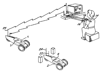
As shown in Fig. 1 of the exemplary drawings, the
invention is embodied in a rugged, compace camera module 2
mounted in a radio controlled toy 4 that is controlled from a TV
- 14 -
1 338909
module 6. The TV module 6 sends signals corresponding to images
and sounds recelved by the camera module 2 to a television
monitor 10. The human operator 14 thus is able to control the
motion of the toy 4 in response to the video picture presented
on the monitor 10. To accomplish control of the motion of the
toy, the operator 14 operates the hand controls 16 on control
modules 18. The control module communicates control system
signals via a transmitter in TV module 6 through a transmitting
antenna 20 to a receiving antenna 22 in toy 4. Camera module 2
incorporates all of the necessary 6ubsystems required to convert
the video image generated by the camera and the audio signal
picked up by microphone 8 into a signal suitable for
transmission via antenna 24 to receiving antenna 26 on TV module
6. Toy 4 includes servo mechanisms and control motors that both
move and control the direction of the toy 4 in response to
commands from the control system receiver in camera module 2.
Previous radio controlled toys have been operated by a
human operator in response to observing the motion of the toy
before him. While thi~ has been a widely used and pleasurable
pastime, an essential element of realism associated with actual
manipulation of the vehicle has been missing, since these
previous toys have not presented the ability to observe the
dynamics of the vehicle from the point of view of an operator
"inside" it. Thus, màny otherwise plea6urable and thrilling
aspects of vehicle operation have not been available in previous
toys.
t 338909
- For example, details of small scale models are not
readily visible when they are any significant distance from the
operator and in order to provide reasonable speed and motion
compared to the observer, the model operates at rates that are
grossly out of scale with the model. Furthermore, these speeds
mean that a very large play area is generally required and the
toys are susceptable to damage and wear and tear from high speed
impacts with surrounding ob~ect~.
The external, remote "point of view" of such toys also
introduces problem~ with control for younger operators. for
example, the operator must tran~pose his actual orientation into
a "forward looking" orientation before he can manipulate the
controls, a very confusing problem if the operator is not
capable or experienced in the operation of such toys or if the
toy is at a distance BO that the precise orientation is not
easily discerned. The operation of such scale radio control
vehicles is not only unrealistic from the point of view of the
observer due to the scale effects and control reversal problem,
but is also lacking in the intimacy with the play environment
that is so appealing to younger children. As a result and due
to the relatively high co~t of radio control components, radio
control models have generally only been part of the relatively
high priced model industry and have not had a significant impact
on that part of the toy market oriented towards younger
children.
... .
- 16 -
1 338909
- The use of television systems in vehicles has primarily
been relegated to very expensive military and commerccial
systems designed for surveillance in remote locations and for
other specialized applications. In general, such systems have
been de6igned to visually capture and return a point of view
only, with the subject of the imagery representing the entire
ob;ective of the mis6ion. The vehicles used in such missions
are full scale, extremely complex systems operating at
predetermined and precise ranges and speeds in order to acquire
radar imagery or accurate photographic data through close-up
telephoto means and then to return that data via transmissions
or internal data storage devices. Such missions are executed
with a clear emphasis on the information gathered, rather than
on the real time feedback of audio environments or visual
effects that involve the vehicle as it interacts with its
environment, or with other vehicles, such as i~ anticipated with
toys.
Furthermore, military, commercial and research systems
have been configured to depict sub~ect environments as
accurately and faithfully as is technically feasible, rather
than to intentionally alter the perspectives of environments for
the purpose of creating special effect~, expanded scope (play
area) or the simulation of ~peeds through enhancement. In
addition to being produced and operated at levels of cost and
complexity that are totally inappropriate for the toy mass
market, such vehicle systems have been intenaed solely for the
purpose of conveylng high-technology imaging and sensing systems
- 17 -
1 33890~
- to predetermined locations where it i6 inconvenient, dangerous
or impossible to have a human operator involved: and once such
imaging or sensing is obtained, the vehicle itself i8 frequently
expendable. The present invention provides a means for bringing
the per60nal sensation of operation of a full size vehicle to
the toy market at modest expense and with a ~imple and robust
product configuration.
Fig. 2 illustrates another one of the many ways in
which the present invention may be implemented in the domestic
environment. In this embodiment, the television camera module 2
is contained in a vehicle 4 that resembles a pet, in this case,
a small rabbit, thereby providing a "watch pet" 4 that may be
used for the remote ob~ervation of a child or other important
part of the operator's surroundings. Such a vehicle also
]5 represents a non-threatening toy for infants and young children
and because of its human operator, appears to exhibit genuine
intelligence. Similar to the vehicle described in Fig. 1, the
"watch pet" 4 contains a camera module 2 that includes
subsystems that encode the video signal for transmission by an
antenna 24 to receiving antenna 26, the TV module 6 and means to
receive control system signals via antenna 22 from the
transmitting antenna 20 of TV module 6 and pass these signals on
to servomechani6ms in the "watch pet" 4 to control its
movements. As an alternative configuration of the invention,
the TV set can be incorporated into either the TV module or
control module. The inset in Fig. 2 illustrates a system in
which the television set 10 is incorporated into TV module 6.
- 18 -
1 338909
-- In order to provide the benefits of the present
invention, it was necessary to configure the components in ways
not normally used for other applications. These configurations
were designed to address the difficult environmental problems
presented by u6e in toys and the cost and manufacturabiliy
constraints associated with producing such toys for the
competitive market, as well as the unique operational
requirements of the invention.
Fig. 3 illustrates in diagramatic form, the basic
sy6tems associated with the present invention. Toy 4 contains
camera module 2 that incorporates the video camera syctem 28, an
audio-video transmitter 30 and a control system receiver 32.
The video camera 28 converts the visual scene before the toy
received via lens 36 through iris 34 to an electronic signal
that i6 then encoded by the audio-video transmitter 30 for
transmission to the transmitter antenna 24. The video camera 28
incorporates a number of features designed to exploit the
capabilities of available technology and optimize them for this
specific application. For instance, the camera 28 incorporates
a wide angle lens 36 that provides the benefits of increasing
the sensation of scale speed while diminishing the effects of
vibration upon the scene being transmitted. The camera
incorporates a simple auto-iris system, consisting of iris 34
and iris control 38, adequate for the purposes of controlling
exposure in a toy such as the present invention and also
provides a miniature microphone 8 and audio amplifier system 40
to simultaneously tran6mit an audio signal of the environmental
-- 19 --
~ 338909
sounds near the toy over the ~ame transmis6ion link as the
video. The camera module 2 also contain6 a control system
receiver 32 that recelves control signals from receiving antenna
22 and after decoding, sends these signals to servos 42 that
operate components of and move the toy in response to the
signals. Battery 44 provides the necessary electrical energy to
operate all of the electronic and electromechanical subsystems
in the toy.
TV module 6 contains an audio-video receiver 46 that
1~ receives the radio frequency (RF) signal transmitted from the
transmittin~ antenna 24 on toy 4 and after decoding, transm~ts
this ~ignal to a conventional television set 10 where the video
picture i6 displayed and the audio signal i~ reproduced. In
response to the image viewed on the television system, the human
operator 14 manipulates a control handset 16 in control module
18 that feed~ control ~ignal~ vla control transmltter 48 to
radio control transmitter 50 and transmitter antenna 20. Thus,
the actions of the operator on the handset 16 control the
operation of toy 4 as described above.
The RF system of the present invention represents a new
approach to short range televislon tran~mission that has been
greeted with approval and encouragement by the Federal
Communications Commission (FCC). Thl6 RF system utilizes a
spread spectrum transmission scheme in order to provide
televi~ion tran6mission utilizlng portions of the
electromagnetic spectrum that are not currently used. In
response to encouragement by the FCC, the inventors have
- 20 -
1 338909
developed this ~ystem to avoid using the conventional techniques
that have already placed such a burden on the transmission
frequency spectrum available for non broadcast use. This
system, which will be described in more detail below,
incorporates a direct sequence spread spectrum modulation of a
carrier, the modulation of which i6 varied by the product of the
baseband composite video and the frequency modulated audio
6ub-carrier signal. The carrier used is in the 902 to 928 MHz
frequency band and the resultant signal provides a low
]0 interference method of transmission. Other benefits and
features of this scheme will be apparent from the detailed
description below.
FREOUENCY MODULATED DIRECT SEOUENCE (FMDS) SIG~ALS
Frequency modulation (FM) of a direct sequence (DS)
electro-magnetic signal produces a combined spectrum that is the
convolution of the FM 2and DS signals. That is, the normal
~ sin x~
direct sequence ~ x J power distribution is shifted in its
entirety as the carrier center frequency is shifted by the
frequency modulation. The composite signal may be expressed as
A cos (wc + wm) t + 90
where the wc + wm term is the (narrowband) FM and that, in turn,
is biphase modulated by2the direct sequence code. The spectrum
/sin x~
therefore has a ~- x J distribution that iB broadened an amount
equal to the deviation of the frequency modulated carrier. With
an 18 Mbps code, the natural direct sequence bandwidth (3dB) is
slightly less than 16 Mhz with an FM deviation~of + 900 Khz (B =
0.2) the 3dB bandwidth can be expected to be expanded to
- 21 -
- 1 338909
approximately 19.6 Mhz, allowing for two significant FM related
sidebands. This means that the resultant overall spectrum will
be in a form similar to that described below:
3~ z (~J7 0~ ~)
s = 3db ~/~ ~/~ Z
M~z
DIRECT SEOUENCE MODULATION
The term "direct sequence" modulation is used herein to
describe carriers that are modulated by a code sequence for the
purpose of spreading the transmitted energy over a wide
bandwidth. The modulation format used, which may be chosen from
several formats (for example, Biphase Shift Key (BPSK), Offset
Quadraphase Shift Key (OQPSK) or Minimum Shift Key (MSK)) is
identical to the format(s) used in data transmission systems,
with the exception that data modulates the carrier in a data
transmitter and a code replaces the data in a direct sequence
system. The specific direct sequence method chosen for use in
the present invention is biphase modulation (BPSK) by an 18 Mbps
code sequence. An expression for this simple modulation format
is A cos wct + 90 where wc is the carrier rate, A is the
amplitude and the +90 or -90 term defines the code modula-
tion. Using this scheme, the code (which is a binary stream)
causes the carrier to be at +90 when a "One" is sent and at -
90 when 25 a "Zero" is sent. With BPSK modulation by an 18
Mpbs code, the frequency spectrum produced has a power distribu-
tion that is (s;~x ) with a main lobe bandwidth of 36 Mhz
(null-to-null) and a 3db bandwidth of 15.84 MHz. This is
illustrated below:
- -t - 22 -
1 338909
3d6 ~h/ = /s, 8~Mh~z
~b/o~\ I_~3J6
36~\
~Z ~
Within the envelope 6hown, the signal is noiselike and has a
lower power density which 18 approximately:
~out (watts)
36xlO6 (Hertz)= Po-~er Density
Those skilled in the art will realize that the above
FMDS concept represents a novel approach to use of the RF
spectrum for the purposes of video transmission and that such
schemes may have broad uses in other systems. In the present
system, it presents many advantages since it makes use of the RF
spectrum in a way that does not intrude on other important uses
of the same parts of the spectrum, an important consideration
for a mass produced toy.
The video transmission link of the above sy6tem may
incorporate, a6 an alternative to a radio frequency transmitter
and receiver, an infrared transmitter and receiver that avoids
the i6sues associated with RF interference and procurement of
approval by the Federal Communications Commission of the
electromagnetic transmission characteristic of the sy6tem. Both
the radio frequency and infrared video transmission systems will
be discu6sed in detail below.
Fig. 4 is an illustration of a toy according to the
present invention, showing the arrangement of the various
components. The toy illustrated is a three-wheeled vehicle 4
- 23 -
1 338909
which incorporates a chassi6 52 upon which two steering wheels54 are mounted and a single drive wheel 56 is also mounted. The
drive wheel 56 i8 powered by a motor 58 driven from battery 44.
Camera module 2 is mounted in chassis 52 and forms a connection
with connector 60 which provides power to the camera module and
a connection with the other subsystems of the toy. The toy
further contains servos 42 which provide control signals to the
steering gear 62 for steering wheels 54 and motor control
signals for motor 58 operating off of battery 44 to drive drive
wheel 56.
CAMERA MODULE
Referring to Fig. 5, the camera module 2 is an
important feature of the present invention, since it forms the
basis for many of the special purpose subsystems used in the
invention and allows the rapid and simple switching of the major
components that it incorporates between various toy~ to increase
the utility of the invention. The camera module 2 is designed
to perform the following functlons of the invention:
l)reception of a visual image and conversion to a
television compatible video electronic signal,
2)reception of ambient sound signals and conversion to
an electronic audio signal,
3)creation of a composite radio frequency signal
incorporating the video and audio signals described above,
4)reception of conventional radio control servo control
signals from an antenna mounted on the toy,
- 24 -
1 338909
5)conversion of the radio control digital 6ervo signals
to analog control voltages suitable for control of
servomechanisms to drive the toy and control its movements, and
6)selection of the audlo-video transmission and radio
control receiving channel.
As shown in FIG. 5, camera module 2 incorporates an
objective lens 68 that is part of the lens system 36 and an
ad~acent microphone (not shown) in the forward facing portion of
the camera module. The camera lens and focal plane is housed
between ob~ective len6 68 and the internally mounted
electronics. The video camera electronics, including -the
audio-video transmitter 30, the control sy~tem receiver 32 and
the audio amplifier 40, is housed inside of the module, which
may in turn, be ea~ily lnserted into the appropriate space in
5 any of a number of toys designed to accommodate it.
LENS SUBSYSTEM
The present invention, designed to enhance the realism
associated with operating miniature toys in a scale environment,
makes use of a wide angle, large depth of field lens that
improves the sensation of scale speed during operation of the
toy and also minimizes the effects of vibration inevitably
encountered due to the relative size of the toy's wheels and the
surfaces on which such a toy is typically used.
Fig. 6 illustrates a lens subsystem 36 of the type used
in the present invention when relatively low quality optical
performance i~ acceptable. Lens 36 incorporates three lens
elements 68, 70, 72 that may be made of premolded plastic in
- 25 -
1 338909
order to provide the wide angle capabil1ties desirable in this
lens, while retaining acceptable optical performance for
applications 6uch as black and white TV. The iris system 34 is
operated in response to a photodetector which may be
incorporated in the camera module body. Alternatively, the auto
iris system incorporating iris control 38 and iris 34 may be
driven by a signal from the focal plane responsive to the light
level falling on the focal plane.
FIG. 7 illustrates a more complex lens suitable for
applications of the toy in which a higher quality optical
performance 18 required such as for color TV when color
correction is required. Six element lens 36 containing lens
elements 74, 76, 78, 80, 82 and 84 provides functional
capabilities similar to the three element lens described above,
in that it provides a wide angle field of view in large depth of
field. However, such a lens system also allows for the
inclusion of color correction by multiple coating of the
intermediate lens elements and higher resolution by spreading
corrections for ray paths over a larger number of components
with the resultant relaxation of the specification of the lens
material. Thus, while the six element lens 36 represents higher
performance, it is still easily fabricated from molded lens and
represents a relativelty 6imple construction for the camera of
the toy.
While the effect desired of the present invention may
be achieved with a variety of wide angle op~ical systems, the
effect has been found to be most interesting and pleasurable for
- 26 -
t 338909
lens systems having a field of view of approximately 150,
measured on the horizontal axis of the field of view. Other
angles between approximately 120 and 170 have also been
found to provide pronounced effects of the type desired here and
still other angles may be desirable for certain applications.
The lens 6ystem must be adapted to the requirements of the
invention and in practice, it has been found that for a CCD
active area of llmm measured on the diagonal, a lens with a
focal length of approximately 4mm produce~ the desired
characteristics and iB simple and economical to construct while
providing an adequate aperture for the llght requirements of the
camera.
The "barrel" distortion associated with a relatively
simple wide angle lens that the invention uses actually provides
a reasonably close simulation of human perception in that the
best resolution is concentrated ln the center of field of view,
just as in the human eye, while the periphery is less detailed
and adds to an illusion of spread in a moving toy. Such a lens
also has a greater depth of field than a "normal" focal length
lens and i~ therefore easier to economically incorporate into a
6imple and inexpensive system such as the camera module of the
pre6ent invention.
FIG. 8 illustrates the electromechanical auto-iris
system of the present invention as viewed through section 8 of
FIG. 6. Microphone 8 is located ad~acent the iris and the case
86 incorporates slots 88 that provide access of outside sounds
to the microphone 8. Iris 34 consists of moving blades 90 and
; - 27 -
1 338909
92 that are driven relative to one another by iris control motor
38 operating on gears 94 and 96 on blades 92 and 90. The
relative motion of blades 90 and 92 alters the opening 98
thereby providing an auto-iris effect.
TV CAMERA
As illustrated in Fig. 9, the TV camera of the camera
module subsystem 2 incorporates a National Television Standard
Committee (NTSC) compatible, 525 line, 2 to 1 interlace, black
and white, charge coupled device (CCD) video camera. This
subsystem also incorporates means to generate an encoded
control signal 10 which can be used to control the pause
control of a video cassette recorder when such a recorder is
attached to the TV module.
The camera of the present invention utilizes a charged
coupled device (CCD) focal plane 100 as the focal plane image
conversion device. This CCD array 100 generates an analog video
output signal which is amplified by a video preamplifier 102.
This signal is then level detected by level detector 104,
amplified by the iris drive amplifier 106 and used to power a
miniature DC iris control motor 38 for automatic control of the
lens iris 34 in response to light level falling on the focal
plane via lens 36. The signal from the video preamplifier 102
is also fed to an automatic gain control (AGC) amplifier stage
108 which also contains a DC rectifier 110 and level detector
112 which allows control from the AGC input of the AGC amplifier
108. The output of the AGC section is amplified by a video
amplifier 114 and fed to the video processor section 116. The
video processor 116 formats the signal into a NTSC standard
- 28 -
1 338909
~ composite video signal by adding a syncronization signal, front
and back porches, black clamp and timing signals. The video
processor 116 also in~ects a peak white voltage level at video
line 15 when the pause command is active.
Sync signals, clamping, blanking and timing signals are
supplied to the video processor by the sync generator section
118. The sync generator ~ection 118 incorporates a crystal
oscillator 120 and frequency dividers 122 which generate
horizontal, vertical and clock timing signals to the vertical
line counter section 124 and the horizontal pixel counter
section 126 which provide addressing to the CCD image p~ckup.
The vertical line counter section 124 also provides line 15
active status which enables the pause control encoder section
128 when the external pause control from the camera connector is
enabled. The video proce6sor 116 output is fed to a video
output amplifier 130 which also provides the feedback signal to
the AGC amplifier 108. The resultant composite video signal is
then fed to the input of the audio-video transmitter described
below.
AUDIO DETECTION AND TRANSM~ K JUNCTION
Fig. 10 illustrates the audio control amplifier 40
incorporated in the camera module 2 to provide a NTSC television
quality frequency modulated audio signal on a 4.5 MHz carrier.
A miniature dynamlc microphone 8 is used for sound
detection and conversion to an electrlcal slgnal. This signal
i5 then amplified by an audio preamplifier~132 and fed to an
automatic gain control and signal limiting stage 134. The
- 29 -
1 338909
resultant signal is then filtered and equalized by apre-emphasis amplifier 136 in accordance with NTSC standards and
again amplified by an audio output amplifier 138 before it is
fed to an audio modulator 140 centered at 4.5 MHz. This 4.5 MHz
center frequency is generated by the frequency synthesizer 142
descrlbed in further detail below. The audio sub-carrier output
is then fed to the bandpass filter 144 in the camera module
audio-video tran6mitter which iB also de6cribed in more detail
below.
AU~I0 VIDE0 TRANSMITTER
Fig. 11 illustrates the audio-video transmitter 30
which iB designed to provide a low-interference method of
transmitting audio and video information in the 902 to 928 M~lz
frequency band. This transmission is accompli6hed by employing
a unique method of modulation referred to as FMDS, whereby a
direct sequence spread 6pectrum modulation of a carrier is
frequency modulated by the product of the baseband composite
video and the frequency modulated audio sub-carrier signals.
The resulting spectrum of this DS/FM proces6 i6 the convolution
2n of these two forms of modulation and each individual signal
spectra. This process begins by summing at summer 141 the
frequency modulated audio sub-carrier through a 4.5 MHz bandpass
filter 144 with the 4 MHz composite video signal filtered by
lowpass filter 147. This summed output is then used as the
frequency modulation signal for the phase locked loop 146
[PLL]. The PLL outputs a low-deviation-ratio frequency
modulated signal (beta <0.2) centered at 72 MHz which is
- 30 -
generated by a fourth harmonic lock of an 18 MHz frequencysupplied by the frequency synthesizer 142. l 3 3 8 9 0 9
This 18 MHz frequency is also used by a discrete
sequence code generator 148 to generate a code which is 8191
bits long. The code generator 148 also receives a one-of-six
band selection which causes the code generator 148 to output
one of six different discrete sequence codes. These codes are
a controlled cross-correlation or multiple access type known
as "Gold" codes. The output of the code generator 148 and the
output of the PLL 146 are then mixed using a balanced mixer 150
which creates a 180 degree phase shift modulation of the 72 MHz
carrier. This produces a pseudo-noise wideband signal with sin
x/x power distribution and average power density of less than
10 microwatts per Hz. This signal is then amplified by an
intermediate frequency (IF) amplifier 152 and again mixed in
15 mixer 154 with a 843 MHz frequency supplied by a surface acoustic
wave (SAW) oscillator 156. This product, centered at 915 NH:,
is then fed to the bandpass filter 143 with 3dB points at 906
MHz and 924 MHz, through power amplifier 158 and to the camera
antenna connector 160 and then to antenna 24. Although the above
design utilizes 72 MHz as the IF, other frequencies may be used
if found more practical for IC integration or less prone to
interference.
PROTOYPE RECIEVER AND TRANSMlll~K DEVELOPMENT
During the course of the development of the present
invention, it became necessary to develop a prototype receiver
and transmitter to test the concepts underlying the frequency
modulated direct sequence (FMDS) signal processing and
1 338909
transmission scheme. The prototypes discussed below were
developed for that purpose using available components in order
to avoid unnecessary duplication and to allow the rapid
substitution of components to evaluate changes in the design.
In practice, the invention will utilize custom designed
electronics consisting of custom and semi-custom integrated
circuits. The receiver and transmitter described below have
been keyed, to the greatest extent possible, to the equivalent
circuit~ in the system described above, in order to illustrate
]~ the relationships between the prototype and final versions of
the receiver6 and transmitters. Also included in Table 1 is a
summary of the circuits that are to be integrated into var~ous
custom and semi-custom chips that will be incorporated into the
production versions of the invention.
PROTOTYPE AUDIO-VIDEO TRANSMIll~
The video transmltter illustrated in Fig. 11~,~ accepts
audio signals from a microphone and video signals from a
television camera and combines them into a standard intercarrier
format. Frequency modulation for the video signal is then used
2~ instead of the more common amplitude modulation to modulate the
signal. As shown in the diagram of Fig. llA,B, a 60 MHz carrier
is frequency modulated by the baseband intercarrier 6ignal and
then spread spectrum modulated by one of six different 18
megabit per second (Mbps) code6. After spread spectrum
modulation, the 60 MHz frequency modulated signal is translated
to 915 MHz by mixing with an 855 MHz fixed osclllator signal.
- 32 -
t 338939
According to the 6cheme used in the prototype
transmitter, the signal i8 independently modulated in three
different ways: l) a 4.5 MHz 6ubcarrier is frequency modulated
by audio information (thi6 is the same as standard television);
2) video and 4.5 MHz subcarrier are combined and used to
frequency modulate a carrier: 3) the frequency modulated (FM/FM)
carrier is spread spectrum (BPSK) modulated.
Channel 6election is accomplished through use of code
division multiplexing. One of six from a family of 8191 "Gold"
codes is selected for spread spectrum modulation and this
providec a means for the receiver to re~ect all but the
correctly coded signal. Six simultaneous transmi6sions are
possible through use of different codes.
The following section is a more detailed description of
the operation of the prototype transmitter.
Video input from a camera source is low pas~ filtered
and linearly 6ummed with the 4.5 MHz audio 6ubcarrier. The 4.s
MHz audio subcarrier is, in turn, frequency modulated by any
audio input signal and is phase locked to a 4.5 MHz crystal
stabilized reference oscillator. The same 4.5 MHz oscillator is
used to generate all but one of the frequencies in the
transmitter. The 4.5 MHz frequency modulated audio subcarrier
i~ phase locked directly to the 4.5 M~tz crystal reference. The
855 MHz signal u6ed for upconverting the 60 Mttz modulated
carrier to 915 MHz is independently generated, using a 6urface
acoustic wave resonator (S.A.W.R.) as the stabillzing element.
After being converted to a 915 MHz center frequency, the FM/FN
- 33 -
`- spread spectrum signal is filtered and amplified to 100
milliWatts. Then it is applied to the transmitter antenna.
1 33890~
CIRCUIT DESCRIPTION
Video input signals are low pass filtered and taken to
a summing junction, followed by an emitter follower. The other
summing junction input is the 4.5 MHz from the 4.5 Mhz Voltage
Controlled Oscillator (VCO) (MC4024). A 20K ohm variable
resistor is employed in the 4.5 MHz summing junction. A 60 MHz
signal is generated by dividing the 4.5 MHz oscillator by 12 and
multiplying the result by 160. 18 MHz is generated by dividing
the 4.5 MHz oscillator by two (2) and multiplying by eight (8)
to allow control of the 4.5 MHz subcarrier level. The 4.5 MHz
phase lock loop consists of the 4.5 MHz crystal controlled
oscillator (74HC00) an exclusive-OR gate phase detector
(74HC86), an RC loop filter and the previously mentioned 4.5 MHz
VC0 (MC4024).
A divide by 12 counter (74LS92) divides the 4.5 MHz
oscillator output and provides 2.25 MHz to an 18 MHz phase lock
loop. It also provides 0.375 MHz to a 60 MHz phase lock loop.
The 18 MHz loop consists of an 18 MHz VC0 (MC4024) a -8 (two
74HC74's) counter, an exclusive -OR phase detector (74hc86) and
an RC loop filter. For 60 MHz generation, a 60 MHz VC0 (MC1648)
is divided by 160 ( 1 :74F74, 74LS90, 74HC74)
4xlOx4
and compared to the 0.375 MHz counted-down reference signal.
MSA-0104 amplifiers are provided at the 60 MHz VCO output to
isolate the VCO and provide sufficient drive power to the
counters and to the spread spectrum code modulator.
- 34 -
1 338909
The 18 MHz VCo is output through a 74HCOO acting as a
clock driver for the code generator. From the code modulator,
where the 60 MHz FM/FM modulated carrier becomes a s~read
spectrum signal, the signal goes to an amplifier (MSA-0104) and
a mixer (SBL-lX) where it is multiplied with the 855 MHz
S.A.W.R. oscillator output. The sum of the 855 MHz signal and
the 60 MHz 61gnal is the desired 915 MHz FM/FM/spread spectrum
modulated signal. The code is generated by employing two shift
register sequence generators (each two 74HC174's, 1/2 74HC74 and
three of five shared 74HC86's). Each generator provides a
linear maximal sequence 8191 chips long. These are then
modulo-20 added together in one of six "Gold" code 6equences.
The combined Gold code sequence is then taken to a driver
(74HC74) that biphase modulates the (SBL-lX) double balanced
code modulator. After the code modulated FM/FM carrier is
upconverted to 915 MHz, it i6 filtered (TOKO 1568HW), amplified
(MAR-8 and MC5809) and output to the antenna.
PROlOlY~E VIDEO RECEIVER
The 915 MHz video receiver illustrated in Fig. 18A,B
incorporates a 915 MHz bandpass filter, an amplifier and a
mixer/converter that converts the signal to 61 MHz and
simultaneously removes the spread spectrum modulation. The
receiver also 6ynchronizes the spread 6pectrum code, demodulates
the signal and outputs a properly modulated channel three
carrier for use by a standard television recelver. The
operation of the receiver, which is described below, is
functionally equivalent to the diagram illustrated in Fig. 18.
- 35 -
1 338909
- Accordingly, to the greatest extent possible and as noted below
in the summary of differences, equivalent functions to those in
Fig. 18 are grouped in Fig. 18A,B.
Referring to Fig. 18A,B, a 915 MHz input signal from
antenna 26 i8 paGsed through a bandpass filter (TOKO 1568HW)
which rejects unwanted 6ignals, is amplified by the amplifier
(MAR-8) and applied to a mixer (SBL-lX). The other input to the
mixer is a spread spectrum signal, identical to the received
signal except for the FM/FM modulation and at a frequency
displaced from that of the input and represents a fixed
frequency spread spectrum modulated 6ignal at 854 MHz. This 854
MHz signal is generated by modulating an 854 MHz carrier from a
S.A.W.R. stabilized oscillator, with a code identical to that
used in the transmitter.
After conversion to 61.25 MHz and removal of the spread
spectrum code modulation, the FM/FM signal is amplified and
filtered. Then the 61.25 MHz frequency modulated signal with
4.5 MHz FM subcarrier, is demodulated by a 61.25 MHz phase lock
loop made up of a 61.25 MHz VCO (MC1648), an RC filter and a
phase detector (SBL-l). The baseband intercarrier signal
consisting of video plus 4.5 MHz audio subcarrier is then sent
to a 61.25 MHz AM modulator and a 4.5 MHz bandpass filter (SFE
4.5). The 61.25 MHz AM modulator output i5 filtered to suppre6s
the carrier and lower sideband, using a surface acoustic wave
filter (KAF-61). This filtering process produces a standard
television signal at the channel three frequenc~.
- 36 -
1 338909
~- The amplitude modulator consists of two amplifiers (MSA-0104)
and a diode modulator. The diode modulator is driven by an
amplifier/emitter follower pair, which varies the current (and
therefore the impedance) in a diode and allows variarion of the
signal amplitude by a factor of approximately 20 db.
The 4.5 MHz filtered ~ubcarrier received goes to an 18
MHz phase lock loop made up of an 18 MHz VCo (MC4024) a divide
by 4 counter (74HC74) and a phase detector (74HC86). When the
4.5 MHz signal i~ present, it drive~ an amplifier (1/4 74HC86)
which, in turn, drives a dlode detector. When thè diode
detection output i6 above zero, the code clock tracks the
incoming signal by allowing the 18 MHz phase lock loop to track
the incoming 4.5 MHz subcarrier. Since the transmitter's 18 MHz
clock is derived from the same 4.5 MHz subcarrier, the
receiver's code clock track6 the transmitter' 8 code clock by
this proce~s.
A separate 8200 bit per ~econd search clock (LM566)
causes the receiver clock to be 6hifted from the nominal 18 MHz,
by deleting clock pul6es at the 8200 pul6e per second rate.
This, in turn, cause~ the receiver code to operate at a rate
8200 bits per second slower than the transmltter whenever the
receiver's code is not synchronized with the transmitter's code.
As soon as the 4.5 MHz subcarrier is recognized (wh~ch
requires the codes to be 6ynced), the clock pul6e deletion is
inhibited, the 18 MHz loop locks and the receiver tracks the
transmitted ~ignal.
-- 37 -- f,
`- 1 338~09
SUMMARY OF PROTOTYPE AND PRODUCTION ELECTRONICS DIFFERENCES
The following i8 a summary of the differences between
the prototype and production transmitters and receivers.
1. The prototype u6es 60 MHz as its IF. This
simplifies construction since parts (filters and resonators)
were more readily available at 60 MHz than 72 MHz.
2. The prototype has no audio preamp, AGC, limiting
or preemphasis. These changes were unnecessary for the
prototype development but are ea~ily implemented to improve
ln production electronlcs performance.
3. The prototype uses discrete oscillators instead of
custom frequency synthesizers, such as the production
electronics will use.
4. The band select switch is not used on the
prototype.
5. In the prototype receiver, the IF is shifted to
produce a vestibule sideband IF signal. This signal is then
demodulated to an intercarrier (video baseband plus FM aud~o
carrier) signal which is then amplitude modulated and fed to VHF
channel 3 of the TV receiver. In the production model, the IF
is not shifted since the RF signals are demodulated to baseband
video and audio. These signals are then amplitude modulated to
VHF channel 3 or 4 as selected by the user.
Compared to the prototype, the production unit will
incorporate the following changes to improve the benefits of the
invention:
- 38 -
t 338909
1. Audio frequency filters will be made with on chip
capacitors and gyrator (synthetlc inductors) circuits.
2. The production system is designed using mostly
untuned amplifiers which require fewer discrete components.
3. Mixers are "active mixer" type which use few
dlscrete components.
4. Oscillators will all be either crystal controlled
or surface acoustic wave which do not require tuning components.
5. Surface mount construction will be utilized.
6. Fixed frequency ceramic filters will be used
wherever possible.
The following is a table of electronic components of
the camera module system that are to be integrated incorporating
the components to be combined and the type and process of
integrated circuits to be used:
- 39 -
1 338909
IC# NAMEPROCESS BLOCKS & DRAWING
IDENTIFICATION NUM8ERS
1. ICl Audio CMOS Audio Preamp - 132
AGC Amp & Limit - 134
Preemphasi~ Amp - 136
Audio Output Amp - 138
Audio Modulator - 140
2. IC2 Sync CHMOS XTAL OSC - 120
Generator Freq. Divider - 122
Sync. Generator - 118
Vertical line count - 124
Horizontal pixel counter - 126
Pause control encod - 128
3. IC3 Video NMOS Video Preamp - 102
Level detector - 104
AGC Amp - 108
Level detector - 112
Video Amp - 114
Video Proc - 116
Video Output Amp - 130
Detector Diode - 110
4. IC4 CCD MOS CCD Image Pickup - 100
5. IC5 LOGIC CHMOS Band Select
Code Generator - 148
6. IC6 FREQ. NMOS Freq. Synthe~izer - 142
SYNTH. PLL - 146
7. IC7 HF MIXER BIPOLAR Mixer - 150
AMP - lS2
- -Mixer - 154
S.A.W. O~cillator - 156
Summer - 141
8. IC8 R/C NMOS AMP - 166
Mixer - 168
3 Stage IF AMP - 172
FM Quad. Detector - 174
Output AMP - 176
Waveform Cond. - 178
9. IC9 D/A CMOS Addres~ Decoder - 180
Data Decoder - 182
D/A Converter - 186
Power Saver - 192
TABLE 1
CAMERA MODULE INTEGRATION SCHEDULE
- 40 -
1 338909
RADIO CONTROL RECEIVER
Fig. 12 illustrates a radio control (RC) receiver 32
designed to operate as a one of six band, eight channel receiver
utilizing high data integrity pulse code modulation (PCM) in the
27 MHz band. The receiver 32 also incorporates a power saver
feature which disables audio/video transmission three minutes
after the R/C information ceases to be updated and automatically
reactivates audio/video transmission upon receiving updated R/C
information. This feature is particularly important for toys
that may be operated by very young children who may not have the
attention span to remember to turn off the toy. Such a feature
is one of many examples in the present invention of
incorporation of special features into the invention to adapt
its use to the specialized requirements of the toy industry.
The 27 MHZ 6ignals (26.995 MHZ, 27.045 MHz, 27.095 MHz,
27.145 MHZ, 27.195 MHZ, 27.255 MHZ) are received from the
antenna 22 through connector 162 and fed through a bandpass
filter 164 to a wideband amplifier 166 which includes an AGC
input. This signal i8 then mixed by mixer 168 with a 16.3 MHZ
~0 frequency 6upplied by the frequency synthesizer 142. The
product is then fed through a 10. 7 MHZ ceramic bandpass filter
170 to a three stage intermediate frequency amplifier 172. The
IF amp output is then demodulated through an FM quadrature
detector 174 with a portion of this signal FED back to the AGC
input of amplifier 166 and again amplified by output amplifier
176. The signal is then shaped and condi'tioned by waveform
conditioner 178 into the original digital bit stream and fed to
- 41 -
-- 1 338909
the address decoder 180 and data decoder 182. The address
decoder 180 generates a strobe signal for each of the eight
channels and feeds them to the camera module connector 184 of
connector 60. The data decoder 182 provide~ serial to parallel
conversion and reconstruction of the original data. This data
is then fed to the digital-to-analog (D/A) converter 186 which
in turn, generates a time multiplexed analog servo po~ition
voltage 190 for each of the eight channels. The data decoder
also provides a data active status control to the audio/video
transmitter DC power saver processor 192. This processor times
and compares this status control with a clock signal 194 from
the frequency synthesizer 142 and disconnects the A/V
transmitter battery supply whenever the power saver disable
control from the camera connector is not enabled and 3 minutes
lS of R/C inactivity has occurred. The frequency synthesizer 142
provides the master clock 194 and multiple reference frequencies
for the circuits in the camera module 2. Each of these
frequencies is phase locked to its internal S.12 MHz crystal
oscillator. Additionally, the frequency synthesizer selects
one-of-six intermediate frequencies (16.295 MHz, 16.345 MHz,
16.395 MHz, 16.445 MHz, 16.495 MHz, 16.545 MHz) as selected by
the band select stage described above.
~ hile the above design utilizes the 27 Mt~z R/C band
commonly used for radio control of air, land and sea model
craft, this design will work equally as well when using the 72
MHz and 75 MHz bands with appropriate chahges to the IF and
filters.
- 42 -
1 338909
-~ INFRARED TRANSMISSION SYSTEM
While the above discussion has described an RF
audio-video transmission system, an attractive alternative means
to transmit the audio-video signal from the toy to the TV module
utilizes an infrared transmitter-receiver system that is
configured for this specific applicatlon. The infrared
transmitter-receiver replaces the radio frequency audio-video
transmitter and receiver described above and provides a benefit
compared to such a system, in that it does not use transmission
1~ frequencies that are susceptible to radio frequency interference
and such a system does not require FCC approval for operation at
the low power levels to be used.
Referring to Fig. 13, an overview of the basic concept
behind the infrared transmission system of the sub~ect invention
is illustrated. Using this concept, an infrared pylon 196
containing a receiver 198 is deployed somewhere in the play
area, more or less centrally located in the range desired for
the toy 4. The infrared receiver 198 converts the signal
received from the infrared transmitter 200 in the toy to a video
2~ signal which i8 then transmitted to the TV module 6 by a coaxial
wire 202 provided. More than one infrared pylon may be used to
cover a larger play area, in which case slave infrared pylon 204
may be "daisy chained" by means of extension coaxial cables 206
to extend the play area in which an adequate signal may be
received. Numerous variations on the placement of the receivers
are possible, which provide flexibility in~the play area to be
used, depending upon the range of the infrared
transmitter-receiver sy~tem and the number o~ pylons used.
- 43 -
1 338~09
Fig. 14 illustrates a schematic diagram of the infrared
transmitter 200 used in the present invention. The video input
from the camera iB fed to amplifier 208 and preemphasiser 210
before being combined in summing amplifier 212 with the audio
input which ha~ passed through an audio preemphasiser 214 and FM
modulator 216 prior to summing. The output of summing amplifier
212 is an NTSC composite video signal which is them FM modulated
by FM modulator 218 and used to drive infrared transmitter light
emitting diode (LED) 220. The output of the infrared
transmitter LED 220 i6 an FM modulated light signal in the
infrared 6pectrum, the exact frequency of which is dependent
upon the LED chosen.
Fig. 15 indicates the infrared receiver 198 of the
present invention which employs, a~ a detector, photo diode 222
the output of which is fed to FM demodulator 224 in order to
reconstruct the NTSC compo~ite video signal 228 transmitted from
transmitter 200. Filter 226 iB used to 6eparate video signal
229 and audio signal 230. The video signal 229 goes through a
buffer amplifier 232 before being conducted to a 75 Ohm video
2~ cable 234. In TV module 6, the video signal is thereafter
amplified by modulator 236 suitable to derive the television
antenna input at VHF frequencies. The audio signal 230 is
passed through bandpas~ filter 238 and FM demodulator 240 in
order to reconstruct the audio 6ignal as it exi6ted prior to
2S amplification and modulation in the transmitter. This 6ignal iB
then amplified by amplifier 242 and fed to a 600 ohm audio cable
244 to drive modulator 236 or in the alternative, a speaker 246
in the TV module 6.
- 44 -
1 3389~9
Fig. 16 illustrates one configuration which may be used
for the infrared transmitter 200. This system uses the infrared
diode 248 as the transmitter power source and the output of the
diode 248 is input via columnating lens 250 to an internal
reflector 252 that focuses the output through an infrared
transparent lens 254 that has a lens curvature designed to
provide the required vertical spatial pattern. The structure of
the transmitter is a plastic housing 256 consisting of a base
portion 258 and an upper portion 260. The upper portion 260 has
reflector 252 formed into it and sandwiches the essentially
cylindrical lens 254 between it and the base portion 258, which
al60 serves as a mount for infrared diode 248 and lens 250.
Fig. 17 illustrates the arrangement of an infrared
receiver 198 of the type used in infrared receiving pylon 196.
The receiver 198 utilizes the construction similar to
transmitter 200 in that a curved reflector 262 collects incoming
light through filter lens 264 and directs it through focusing
lens 266 towards infrared detector 268 mounted in the base of
housing 270 of the receiver. Lens 266 serves to collect the
infrared signal directed towards the lens from reflector 262 and
focus it upon the active area of detector 268. Reflector 262 is
formed in the upper portion 272 of housing 274. Upper portion
272 also has formed into its top surface a lightshade 278 to
prevent the lntroduction of stray light radiation from 60urces`
above the receiver 198. The upper portion 272 and lower portion
270 sandwich filter lens 264 between them to form hou~ing 274.
Reflecting surface 262 is formed of a silvered layer on the
reflector surface formed in the material of upper housing 272.
- 45 -
1 338909
TV MODULE
The TV module performs the following functions in the
present invention:
1) receives and demodulates the audio/video FMDS 6ignal or IR
signal;
2) remodulates the audio/video ba6eband signals into NTSC TV
channel 3 or 4 RF signal:
3) decodes the pause control 6ignal for remote control of an
external video cassette recorder; and
4) generates and transmit6 pulse code modulated radio control
s~gnal~ as derived from an operator input through control 6tick
inputs,
5) selects one of the channel6 cho6en at the camera module for
R/C transmi66ion and audio-video reception by use of a channel
selection switch
Each of the above function6 i6 illustrated in further
detail in the following description and the accompanying
exemplary drawings.
AUDIO/VIDEO RECEIVER
Fig. 18 illu6trates the audio/video receiver 46
designed to receive the audio/video signal from the transmitter
30 de6cribed above. The audio and video signals received are
remodulated to VHF channel6 3 or 4 for reception by a standard
(NTSC) television receiver.
The broadband signal is fed from the antenna 26 through
a 915 MHz dual helical re60nator bandpa6s filter 278 to an AGC
amplifier 280. The output from thls amplifler is then actively
- 46 -
1 338909
mixed by mixer 282 with the product of the 18 MHz direct
sequence spreading code generated by code generator 284 and the
843 MHz S.A.W. reference oscillator 286, which are mixed in
mixer 288 and amplified by amplifier 290. This produces a 72
MHz IF frequency which is then fed to the slope detector 292.
In the slope detector 292, the nignal is first bandpass filtered
at 72 MHz by bandpass filter 294, amplified by amplifier 296 and
then fed to an envelope detector 298. The output of the
envelope detector 298 is then fed to the AGC input of the 915
].0 MHz amplifier 280 and to the 4 MHz lowpass filter 300 which
outputs the original baseband video signal. The output of the
lowpass filter 300 is also fed to the video line counter 302
where pause control information is decoded from video line 15
and passed along to the pause control relay 304. The output of
the envelope detector 298 is also fed through a 4.5 MHz ceramic
bandpass filter 306 which outputs the audio eub-carrier to a
quadrature detector audio demodulator acting as an audio
discriminator 308 and which outputs the original baseband audio
signal.
The audio sub-carrier signal is also fed to a phase
locked loop [PLL] 310 which generates the 18 MHz clocking
frequency for the sync detector 312 and code generator 284. The
sync detector 312 allows sync ~lip compared to the code
generator 284 by preventing periodic clock pulses from reaching
the code generator 284. This slippage occurs only until the
code generator 284 locks to the transmitt~r code generator
codes. The code is slipped one complete cycle in approximately
- 47 -
1 338909
one second. Thus, using thi~ system, the maximum delay before
lock is one ~econd. The code generator 284 and band select
logic 314 are identical to those described for the audio-video
transmitter. The audio and video baseband nignals are then
remodulated by a TV modulator 316 to TV channel 3 or 4 and fed
to an antenna relay 318 which replaces the TV antenna signals
with the output of the modulator whenever the TV module AC power
is on.
R~C TRANSMlll~K
Fig. 19 illustrates a radlo control (R/C) transmitter
designed to convert operator control ~tick 16 positional
information into an electrical signal and then transmit this
information to the compatible radio frequency receiver 32 in the
toy 4 described above.
The control handset~ 16 typically supply a 0-5 volt
proportional signal approximately 30 times a second to an analog
data selection and multiplexer 320 which is sequentially
addressed by the address generator 322. The analog multiplexer
320 output is fed to a analog to digital (A/D) converter 324 and
output as 8 bit parallel data to the parallel-to-serial
converter 326. The parallel-to-serial converter 326 produces a
pul6e code modulated (PCM) serial bit stream containing word
sync, channel address and channel data. The timing and address
generator 322 receives a 4800 Hz clock from the frequency
synthesizer 328 which is used to generate control 6tick and
channel addresses and convert cycle timing for'the A/D converter
324. The output of the parallel-to-serial converter 326 is fed
- 48 -
1 338909
-
to the scaling amplifier 330 used to drive the varactor diode
332 which frequency shift key (FSK) modulates a 27 MHz voltage
controlled oscillator (VCO) 329 inside the frequency synthesizer
328. The frequency syntheslzer 328 generates the appropriate 27
MHz frequency based on the band selected similar to that
described above for the transmitter. The FSK output from the
frequency synthesizer 328 is fed to a final power amplifier 334
and the output of amplifier 334 is fed to a 27 MHz bandpass
filter 336 and to the TV module antenna 20.
n CAMERA MODULE CONSTRUCTION
Referring to Fig. 20, the camera module 2 of the
present invention i8 configured to advantageously incorporate
and combine mo~t of the important element~ associated with the
television camera, audio-video transmitter and R/C receiver
subsystems. Camera module 2 incorporates a water-resistant case
338 formed in two parts, a forward member 340 and rearward
member 342, that are 6ealed at their ~unction 344 by an
elastomer seal 346 attached to the aft part of the forward
housing 340. Seal 346 also 6eals and contains the circuit
boards in their positions and urges the CCD focal plane 100
forward against the focal plane stop~ 370.
Lens 6ystem 36 is mounted in the forward housing 340
and contains lens elements 68, 70, as described above, to
provide a wide angle lens configuration when combined with lens
element 72 mounted in aft lens housing 348 and operating through
the focal length of the len6 350 onto CCD focal plane 100. An
audio microphone 8 (not shown in this figure) is mounted
- 49 -
1 338909
ad~acent to the lens 36 and provides an electrical 6ignal to one
of two electronics boards 352, 3S4 mounted within the body of
the camera housing to incorporate the vldeo camera, transmitter
and receiver electronics, as described above. Connector 184 is
designed to be engaged by external connector 356 upon insertion
of connector 356 through opening 358 in the aft part of the
housing 342. A rotating door 360 is designed to prevent
intrusion of foreign ob~ects or contaminants when the module is
not in use. Ball mounting system 362 receives an external ball
mount 364, thereby allowing the camera module 2 to be pivoted
about ~aid ball mount 364 in order to direct its field of view
in a desired direction. An elastomer disk 365 is inserted into
mounting system 362 above, to po~itively preload h~ll mount 364
when it is inserted, thus tending to prevent undesired movement
of the camera module 2 around ball mount 364.
Referring to Fig. 21, which is a perspective, exploded
view of the camera module 2, a transparent ob~ective lens
assembly 68 is mounted in the forward end of the body and
protects the internal components of lens 36, iris assembly 34
2~ and CCD focal plane 100. The electronics includes a pair of
circuit boards 352, 354, one over the other, with the Charge
Coupled Device (CCD) focal plane 100 positioned in the forward
part of the module and a multi-pin connector 184 at the rear.
This core assembly slides into the case 340 from the rear and is
retained by the rear cap 342. The desired ruggedness is
achieved by using a high impact plastic such as polycarbonate
for the two-piece case. Such material has the combined strength
- 50 -
1 338~09
and dimensional stability to permit the precise positioning of
bosses and miniature threaded holes as integral parts of the
design.
The outer lens assembly is installed by press fit into
the case. The optical elements of the lens system have a number
of features designed for this application. The outer lens
surface 66 of the objective lens 68 is flat and less susceptible
to abrasion than a convex surface. A cyanacrylate or silicon
sealer is added at installation to make the seam watertight.
The molded forward case 340 includes stepped recesses 348 and
370 which serve to locate the lens housing element6 and focal
plane. The rear section of the optics package includes molded
lens element 72 which mounts against shoulder 348 and includes
recess 372 to house iris 34. Although a solid-state iris of the
liquid crystal type may be incorporated when it is sufficiently
developed for thi6 application, a simple electro-mechanical unit
of the type well known in the art, is shown in the camera's
forward section ad~acent to the microphone 8. Two moving blades
90, 92 form a diamond shaped iris aperture when they are driven
in opposite directions through gears 94, 96 by a small gear on
the iris control motor 38, which re6ponds to a 6ignal
proportional to signal 6trength at the focal plane from the
camera circuitry as described above. A channel selector switch
374 is incorporated into the body of the camera module to allow
for ~election of one of the six channels available for operation
of the audio-vldeo transmitter and R/C rec~iver 6ystem. The
switch iB actuated by inserting and rotating a coin or another
simllar ob~ect in slot 376 in switch 374.
- 51 -
1 338~09
The audio microphone 8 i~ located next to the iris 34
and is sealed against slots 379 in the case through the use of a
mylar diaphram 380. This seal permits the nose of the camera
module to be immersed in water for short periods. When the
camera is inserted into a water resistant accessory housing, the
camera module can be used on model boats, or in wet
environments.
As shown in Fig. 21, the image formed by the lens
system 36 focuses across an air gap on the face of the CCD focal
plane 100. Behind the focal plane, the CCD focal plane array
includes image processing circuits which terminate in a
connector 184 which is soldered directly to the circuit boards
352, 354. A CCD support structure 368 supports the front of the
upper and lower circuit board 352, 354. Pressure from the rear
elastomer seal 346 holds the CCD focal plane 100 against CCD
support structure 368 in the case.
Whenever possible, components of the camera module
serve more than one function. The integral ball ~oint mount 362
which accepts the tripod swivel mount ball 364 is an example.
This component, located near the center of gravity of the camera
module 2, also places it near the center of the printed circuit
boards 352, 354, attached to the removable core assembly 378.
When in place, it spans the interior space transmiting the loads
of tripod use to the other side of the case 338. It is secured
by a screw threaded ring 380 installed from the outside. Thus,
the ball joint mount 378 serves not only as a standoff/support
for the boards, but also ~oins them electrically through
molded-in leads soldered to each board.
- 52 -
-- 1 3 3 8 9 0 9
It will be appreciated by those in the art that the
above invention represents a sub~tantial improvement in radio
controlled toys, since it allows the operator to en~oy the point
of view of both the miniature model or toy as well as the play
area surrounding it, in a simple, robust and relatively
inexpensive package. While the invention ha6 been described in
the context of a toy that i6 primarily operable on land, the
components of the system have been designed to advantageously be
applied to alrborne or waterborne toys, including submersibles,
or toys that may be directly manipulated by the child with
feedback provided to the child from a remote playmate who is
able to view the operation of the toy through a TV or monitor.
The unique presentation of the point of view of the toy by the
present invention creates an almost unlimited mean~ of expanding
the en~oyment of radio controlled toy6 while meeting the economy
and manufacturability requlrements of the toy industry.
Previous radio controlled toys have not provlded realistic
motion, since the speeds also scale to the equivalent of four to
seven hundred miles per hour for model cars and very high speeds
2~ for aircraft, representing speeds far too fast for human
reaction if the point of view is from inside the vehicle, as
with the present invention. The present invention may therefore
use far slower 6peeds with the resultant improvement in safety,
robustness and "friendliness" through ease of operation for
young children, thereby expanding the enjoyment of such toys to
younger children who have thus far been prohiblted from en~oying
radio controlled toys for the above reasons and cost
consideratlons.
- 53 -
1 338909
Thus, the present invention provides an extraordinary
and unexpected benefit to the en~oyment of radio controlled toys
as well as wired toys and non-motorized toys, while meeting the
economy and manufacturability requirements of the toy industry.
In view of this extraordinary promise, while a number of
preferred embodiments of the invention have been illustrated and
several particular forms of the invention have been described,
it will al60 be apparent that various modifications can be made
without departing from the ~pirit and scope of the invention.
Accordingly, it is not intended that the invention be limited
except as by the appended claims.
- 54 -