Language selection

Search

Patent 2015382 Summary

Third-party information liability

Some of the information on this Web page has been provided by external sources. The Government of Canada is not responsible for the accuracy, reliability or currency of the information supplied by external sources. Users wishing to rely upon this information should consult directly with the source of the information. Content provided by external sources is not subject to official languages, privacy and accessibility requirements.

Claims and Abstract availability

Any discrepancies in the text and image of the Claims and Abstract are due to differing posting times. Text of the Claims and Abstract are posted:

  • At the time the application is open to public inspection;
  • At the time of issue of the patent (grant).
(12) Patent: (11) CA 2015382
(54) English Title: THREAD-CUTTING SCREW
(54) French Title: VIS AUTOTARAUDEUSE
Status: Expired
Bibliographic Data
(52) Canadian Patent Classification (CPC):
  • 85/106
(51) International Patent Classification (IPC):
  • F16B 25/04 (2006.01)
  • F16B 25/00 (2006.01)
  • F16B 39/30 (2006.01)
(72) Inventors :
  • DICKE, ROBERT (Germany)
(73) Owners :
  • ROMMEL, ERWIN (Germany)
(71) Applicants :
  • ROMMEL, ERWIN (Germany)
(74) Agent: SMART & BIGGAR
(74) Associate agent:
(45) Issued: 2001-05-22
(22) Filed Date: 1990-04-25
(41) Open to Public Inspection: 1990-10-25
Examination requested: 1996-05-02
Availability of licence: N/A
(25) Language of filing: English

Patent Cooperation Treaty (PCT): No

(30) Application Priority Data:
Application No. Country/Territory Date
G 89 05 189.0 Germany 1989-04-25

Abstracts

English Abstract


A thread forming screw has a shaft with a head and
a tip at opposite ends of the shaft. The screw also has a
thread which starts at the tip and runs at least partially
along the shaft towards the head of the screw. The thread
has first and second opposing flanks facing the tip and the
head of the screw respectively. The thread, at least at
the tip of the screw, has recesses in at least the first
flank thereof. The recesses, which form undulations in the
thread have upper borders which form an edge on the thread
and are asymmetrical with a deeper front face and a
shallower rear mace in screw in direction of the thread.


Claims

Note: Claims are shown in the official language in which they were submitted.


-1-
THE EMBODIMENTS OF THE INVENTION IN WHICH AN EXCLUSIVE
PROPERTY OR PRIVILEGE IS CLAIMED ARE DEFINED AS FOLLOWS:
1. A thread forming screw having a shaft with a head and a tip at
opposite ends of said shaft and a thread which starts at the tip and runs at
least partially along the shaft of the screw, said thread having first and
second opposing flanks facing said tip and said head of said screw
respectively, the thread, at least at the tip of the screw having recesses in
at
least the first flank thereof, the recesses, which form undulations in the
thread, having upper borders which form an edge on the thread and being
asymmetrical with a deeper front face and a shallower rear face in screw in
direction of the thread.
2. A thread forming screw as claimed in Claim 1 wherein
transition between the recesses and the thread flank is in the shape of a
parabola with an axis which is shifted in the screw in direction by an acute
angle .alpha. toward a mid-line of the longitudinal axis of the screw.
3. A thread forming screw as claimed in Claims 1 or 2 with
decreasing distances between the recesses toward the tip of the screw.
4. A thread forming screw as claimed in Claim 1 with recesses on
the second flank of the thread opposing the recesses on the first flank of
the thread.

Description

Note: Descriptions are shown in the official language in which they were submitted.


CA 02015382 1999-07-29
- 1 -
THREAD-CUTTING SCREW
The present invention concerns a thread-cutting
screw with a single thread or multiple threads, a screw tip
and a screw head where the edge forming the screw tip is at
least partially undulating and the thread runs to the end
of the screw tip and the undulating thread tip has
indentations that interrupt the flank surface at least on
its flank surface facing the screw tip and whose upper
limit is the edge itself on the screw tip and at least on
the first adjacent flight of the screw shaft.
Such a screw is already known from German Patent
Application P 33 35 092.2. In this known slotted screw,
the indentations are designed so they are symmetrical with
the midline of the wavy edge so that indentations are
shaped as symmetrical paraboloids. This known slotted
screw has a reduced screwing torque and an increased
unscrewing torque in comparison with those known in the
past.
The present invention is based on the problem of
improving this known screw in such a way as to yield a
further reduction in screwing torque with a simultaneous
increase in unscrewing moment.
According to this invention, this is accomplished
by the fact that the indentations are arranged
symmetrically, so their front flank face in the screw-in
direction is steeper than the rear flank face as seen in
the screw in direction. It is also expedient here for the
transition from the indentations to the flank face to be in
the shape of a parabola whose axis is shifted by an acute


CA 02015382 1999-OS-20
SN 2,015,382
- 2 -
angle a in the acrew-in direction towards the midline of
the wavy edge forming the upper limit and running through
the longitudinal axis of the screw.
It is a7.so expedient for the indentations to be
designed so they are opposite each other on both flank
faces of the flight. Due to the design according to this
invention, the :resistance is thus lower in screwing in the
screw due to the flatter design of the rear part o the
parabola as seen in the screw-in direction, whereas
unscrewing the screw according to this invention is more
difficult due to the steeper arrangement of the parabola
surface positioned farther forward in the screw-in
direction.
On the x>asis of the practical example shown in the
accompanying figures, this invention will now be explained
in greater deta~'~1.
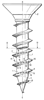
Figure 1 shows a partial view of a screw according
to this invention;
Figure 2 shows a partial section along line A-B in
Figure 1;
Figure 3 shows a partial section through an
indentation in t:he flank face of the screw according to
Figure 1 along t:he line of intersection C-D in Figure 2.
As Figure 1 shows a screw according to this
invention consi~;ts of a screw shaft (1), a screw head (2)
and a simple slit or cross-slit plus a screw tip (3).
Screw shaft (1) has the same diameter over its entire


CA 02015382 1999-OS-20
SN 2,015,382
- 3 -
length and screw tip (3) tapers continuously to the end of
the screw shaft. A screw thread (4) running to the end of
screw tip (3) is provided on screw shaft (1) and screw tip
(3). Edge 5) o:E the flights that form thread (4) follows
an undulating p<~ttern, i.e., there is a smooth sequence of
elevations (tips of the waves (12)) and indentations
(valleys of the waves (13)) and the outside diameter of the
thread is determined by the distance of thread edge (5)
from the centra:L axis of the screw in the area of the tips
of the waves (12). In addition, recesses (6) are also
formed in the area of the valleys (13) in the thread edge
(5) at least on the face (10)of each slight facing the tip
of the screw. Edge (5) in the area of the respective
valley (13) forrns the upper limit of recesses (6). As
indicated by Figure 2 in combination with Figure 3, the
recesses (6) are' designed so they are asymmetrical, so
their flank facE~ (7) which faces in the screw-in direction
of the screw according to this invention is steeper than
the rear flank i=ace (8) as seen in the screw-in direction
of the screw. The transition (9) to the other flank face
of thread flank (10) is designed as a parabola here. Axis
(4) of the parabola is shifted toward midline (15) of the
wavy edge (5) forming the upper limit running through the
longitudinal axis x-x of the screw by an acute angle a in
this screw-in direction. Preferably, there is a pitch of
the recesses over one flight of about 8 to 13 recesses (6).
The recesses (6) may be located over the entire area of the
thread, i.e., even on the tip of the screw itself. The
depth of recesses (6) is preferably 1/3 to 1/3 the height H
of the thread. As shown by the figures, there is a fluid
transition between recesses (6) and the remaining area of
the thread flank:, so there are no sharp edges and thus
cutting affect i.s prevented. The same thing is also true
of the transition between valleys (13) and peaks (12) of
edge (5) where the valleys (13) from the border of recesses
(6). The peaks (12) are designed so they are relatively


CA 02015382 1999-OS-20
SN 2,015,382
- 4 -
short in comparison with the valleys.
In the ~>ractical example, illustrated in Figure 1,
the recesses (6) are arranged so they are opposite each
other and are symmetrical with edge (5). However, it is
also within the scope of this invention to provide recesses
(6) on flank faces on only one side.

Representative Drawing
A single figure which represents the drawing illustrating the invention.
Administrative Status

For a clearer understanding of the status of the application/patent presented on this page, the site Disclaimer , as well as the definitions for Patent , Administrative Status , Maintenance Fee  and Payment History  should be consulted.

Administrative Status

Title Date
Forecasted Issue Date 2001-05-22
(22) Filed 1990-04-25
(41) Open to Public Inspection 1990-10-25
Examination Requested 1996-05-02
(45) Issued 2001-05-22
Expired 2010-04-25

Abandonment History

There is no abandonment history.

Payment History

Fee Type Anniversary Year Due Date Amount Paid Paid Date
Application Fee $0.00 1990-04-25
Registration of a document - section 124 $0.00 1990-11-28
Maintenance Fee - Application - New Act 2 1992-04-27 $50.00 1992-04-24
Maintenance Fee - Application - New Act 3 1993-04-26 $50.00 1993-04-19
Maintenance Fee - Application - New Act 4 1994-04-25 $50.00 1994-03-17
Maintenance Fee - Application - New Act 5 1995-04-25 $75.00 1995-03-16
Maintenance Fee - Application - New Act 6 1996-04-25 $75.00 1996-04-09
Maintenance Fee - Application - New Act 7 1997-04-25 $75.00 1997-04-17
Maintenance Fee - Application - New Act 8 1998-04-27 $150.00 1998-04-02
Maintenance Fee - Application - New Act 9 1999-04-26 $150.00 1999-04-13
Final Fee $150.00 1999-10-04
Maintenance Fee - Application - New Act 10 2000-04-25 $200.00 2000-04-12
Maintenance Fee - Application - New Act 11 2001-04-25 $200.00 2001-03-09
Maintenance Fee - Patent - New Act 12 2002-04-25 $200.00 2002-03-14
Maintenance Fee - Patent - New Act 13 2003-04-25 $200.00 2003-02-07
Maintenance Fee - Patent - New Act 14 2004-04-26 $250.00 2004-03-11
Maintenance Fee - Patent - New Act 15 2005-04-25 $450.00 2005-02-24
Maintenance Fee - Patent - New Act 16 2006-04-25 $450.00 2006-02-21
Maintenance Fee - Patent - New Act 17 2007-04-25 $450.00 2007-03-08
Maintenance Fee - Patent - New Act 18 2008-04-25 $450.00 2008-03-07
Maintenance Fee - Patent - New Act 19 2009-04-27 $450.00 2009-04-06
Owners on Record

Note: Records showing the ownership history in alphabetical order.

Current Owners on Record
ROMMEL, ERWIN
Past Owners on Record
DICKE, ROBERT
Past Owners that do not appear in the "Owners on Record" listing will appear in other documentation within the application.
Documents

To view selected files, please enter reCAPTCHA code :


To view images, click a link in the Document Description column. To download the documents, select one or more checkboxes in the first column and then click the "Download Selected in PDF format (Zip Archive)" or the "Download Selected as Single PDF" button.

List of published and non-published patent-specific documents on the CPD .

If you have any difficulty accessing content, you can call the Client Service Centre at 1-866-997-1936 or send them an e-mail at CIPO Client Service Centre.


Document
Description 
Date
(yyyy-mm-dd) 
Number of pages   Size of Image (KB) 
Abstract 1999-05-20 1 19
Description 1999-05-20 4 138
Description 1999-07-29 4 139
Cover Page 2001-05-03 1 32
Claims 1999-04-07 1 35
Cover Page 1994-04-01 1 23
Abstract 1994-04-01 1 34
Claims 1994-04-01 2 81
Drawings 1994-04-01 2 62
Description 1994-04-01 4 182
Drawings 1999-03-03 2 44
Claims 1999-03-03 1 33
Representative Drawing 1999-07-16 1 26
Representative Drawing 2001-05-03 1 10
Correspondence 2006-09-29 1 13
Correspondence 2006-09-29 1 15
Correspondence 1999-04-06 1 105
Prosecution-Amendment 1999-04-07 2 69
Correspondence 1999-05-20 6 184
Prosecution-Amendment 1999-07-29 2 68
Correspondence 2001-03-07 1 17
Correspondence 1999-10-04 1 35
Correspondence 2006-08-23 2 63
Fees 1997-04-17 1 45
Fees 1996-04-09 1 43
Fees 1995-03-16 1 41
Fees 1994-03-17 1 34
Fees 1993-04-19 1 29
Fees 1992-04-24 1 29
Assignment 1990-04-25 2 89
Assignment 1990-07-18 2 58
Correspondence 1990-04-25 1 26
Prosecution-Amendment 1996-05-02 1 46
Correspondence 1996-06-04 1 59
Prosecution-Amendment 1999-02-01 1 43
Prosecution-Amendment 1998-07-31 1 39
Prosecution-Amendment 1997-06-26 2 51