Note: Descriptions are shown in the official language in which they were submitted.
- 2016870
FIELD OF THE INVENTION
This invention relates to a dispenser for storing and mixing several
components. Particularly, this invention relates to such dispenser that
s comprises many compartments for mixing at least two components.
i
BACKGROUND OF THE INVENTION
- Many pharmaceutical preparations are unstable when admixed in their
carriers thus exhibiting substantially reduced potency and shelf-life, and the
state of nature of many polymers and amalgamates necessitates separation
into their component parts, until immediately prior to use.
~s
In the case of plural component medications, such as vaccinations, liquid
diluents and solid Iyophilized components are maintained in separate glass
vials with pierceable rubber stoppers. Preparation necessitates a lengthy
mixing procedure wherein the stopper of the diluent vial is first pierced with
20 a sterile needle and syringe, and the diluent withdrawn into the syringe.
The needle is subsequently withdrawn from the first and inserted in to the
second vial and the diluent injected thereto. The medication is admixed and
withdrawn into the syringe for injection. In the case of most vaccinations
which are typically given by the intramuscular or subcutaneous route,
25 injection procedure requires that the plunger of the syringe be withdrawn
slightly after insertion of the needle into the patient. If at that time the
hypodermic has been placed into a blood vessel, blood will be aspirated into
the syringe. This withdrawal test allows replacement of the needle to a
nonintravascular site. This test is likewise performed to confirm
30 intravascularity when a mixture is to be given intravascularly.
The inherent problems of said procedure include considerable expense in the
form of: a lengthy procedure, high cost of separate containerization,
storage and refrigeration, and the generation of a substantial quantity of
35 medical waste, its problematic disposition and the consumption of
resources, in a time where conservation is of particular importance.
Furthermore, repeated insertion and retraction of the sterile needle into the
vial stoppers, which are externally unclean and contaminated with microbial
40 organisms increases greatly the risk of contamination of a sterile medical
preparation with external environmental contaminants.
Additionally, foreign body contamination by small rubber particles cut from
the vial stoppers by the razor sharp beveled needle, upon insertion,
C ~
, ~. . -
- 2016870
represents a hazard, as these may be injected along with the medication into
the patient.
Those skilled in the prior art will recognize this similar disadvantage as seen
s with prior art apparatuses using pierceable or bursting diaphragms.
Solowey, in Canadian Pat. No. 891,356, teaches the use of a bursting
diaphragm wherein a cap-like stopper plug with a bursting bottom is
ruptured by pressure generated by a specially designed plunger which
lo inserts into said cap in a male/female interaction, said cap then depressed
with the plunger to expel the syringe contents.
The possibility for the ruptured membrane to dislodge and clog up the distal
syringe aperture or enter the patient parenterally, is recognized. Said special
15 plunger furthcr necessitates complex specific manufacturing and limits
expulsion due to its flat bottom.
Similar disadvantages are recognized with bulb type expulsion systems.
Williams, in Canadian Pat. No. 766,545, teaches the use of a bulb type
20 syringe which requires a screwing action and bursting of a diaphragm.
Notwithstanding the complex thread machining, the shortcomings of
inaccurate dosage are recognized.
Similarly, the prior art utilizing inserts may minimize the accuracy of dosage
2s quantity delivered.
Of the various types of plural compartment containers taught in the patents,
bypass type syringes require the movement of a partition into a bypass area,
wherein a liquid phase is forced around said partition by the action of a
30 plunger, so as to effect admixing.
There exists however, with regards to the herein above mentioned, a
tendency toward a variety of disadvantages which include, a tendency for
entrapment of medication at the bypass zone with retention of large residual
3s volumes of medication in the syringe; a reverse propulsion of contents and
more difficultly performed withdrawal test.
For instance, Canadlan Pat. No. 894,352 (Walecka) utilizes a stopper and
plunger that encases two compartments which communicate via an
40 enlargement in the syringe body ~bypass). As the plunger is depressed, the
translation force moves said stopper into the enlargement or bypass zone.
Disadvantageously, as the stopper passes the bypass zone enlargement site
entering an area of normal diameter, it thereby seals off the distal
compartment and precludes the inclusion of the entire volume of proximal
-
., '
' '~`, ' . ~
.;
2016~70
medication in dispensation. Additionally, a fixed bypass fixes the volume of
proximal and distal compartment sizes necessitating a specific syringe for
each specific medication volume.
s Szwarc, in Canadian Pat. No. 1,262,327, teaches a bypass arrangement
wherein a slight enlargement placed laterally on the syringe body, sealed
proximally by a movable stopper. As in the herein above mentioned bypass
arrangement, fluid flows preferentially around the bypass until said stopper
engages the distal non-bypass zone. At or about that point is encountered a
o tendencv for retropulsion of a portion of the medical volume in a proximal or
backward direction out of the syringe barrel, potentially aerosolizing harmful
biologics or vaporous chemicals. To prevent said extra-syringation of
medication, complex flanges must be included to catch the spilling
medication.
It is known from the prior art that utilizing a cannular bypass like in
Canadian Pat. No. 1,185,858 ~Lissenburg et al), may create a tendency for
difficult visualization of blood during the withdrawal test.
20 Zackheim, in Canadian Pat. No. 888,333, teaches a valve seated across a
syringe body propped up by a ledge. Upon depression of a plunger, said
valve is moved off its ledge by tilting into a perpendicular orientation with
respect to its original position, so as to effect fluid bypass and admixing of
components. A tendency for said valve to remain perpendicular, thereby
25 precluding expulsion of a fluid column approximately equal to the
perpendicular height of said valve as it becomes entrapped at the distal inner
syringe barrel in a perpendicular fashion by the plunger, is recognized.
Furthermore, smooth ejection is precluded, in that the ledge must be
30 bypassed by the syringe plunger. This may lead to patient discomfort and
pain due to the cutting action of the razor sharp, beveled, moving needle in
the patient's dermis or muscle, and hazard in the case of Veterinary
Medicine, wherein rapid painfree injection is necessary in intractable
animals.
Other prior valve sealing apparatuses include multi-component syringes
(Canadian Pat. No. 1,001,032) which require costly manufacturing and
precision design.
40 Dupont et al, in US. Pat. No. 4,563,174, teach a syringe separated into
parts by a complex rotatable seal valve double plunger system. The
necessary precision and material usage makes this arrangement unsuitable
for single use, being cost prohibitive and generating undue medical waste.
C'`
- ' ' ~ ' '
.....
.: .
2~16~70
, 5
The syringe apparatuses herein above eluded tol represent plural-
compartment containers but none have adequately addressed the need for a
simple, cost effective, low wastage, reliable pluro-compartment mixing
dispensing container. Doctors, and especially veterinary doctors, strongly
s recognize the need for a pluro-compartment mixing dispensing container
which addresses the hereto mentioned medical requirements, while
adaptable to current manufacturing procedures and current theories of
conservation.
OBJECTS OF THE PRESENT INVENT!ON
The object of the instant invention is to adequately address the need for a
simple, cost effective, low wastage, reliable, pluro-compartment mixing
dispensing container syringe which lends itself to all the herein mentioned
medical requirements, while adaptable to current manufacturing procedures
and current theories of environment and resource conservation.
It is a general object of the present invention to provide a dispenser
arrangement for use particularly in packaging and subsequent dispensing of
fluid-flowable materials.
SUMMARY OF THE INVENTION
The present invention generally provides a partitioning stopper for a two
compartment syringe assembly for dispensiny a liquid medication derived
from the mixing of a first and a second component, one of the components
being a liquid, the assembly having
a cylindrical medication barrel having a forward (i.e. distal) medication
delivery end and a rearward (i.e. proximal) end and
an axially slidable plunger for closing off the rearward end of the
barrel, the plunger being disposed in fluid tight engagement in the barrel,
the partitioning stopper bein~q separated from the plunger being
configured for dividing the barrel into the two compartments, the partitioning
stopper being configured for slidable fluid tight engagement in the barrel, the
stopper having a fluid passageway extending axially therethrough, the fluid
passageway havin~q a pop-out blow plug disposed for fluid tight engagement
therein, the blow plug being displaceable, so as to unblock the fluid
passage, under fluid pressure, as induced by movement of the plunger, the
partitioning stopper being configured for forward displacement by abutting
contact with the plunger as the plunger undergoes forward movement,
the partitioning stopper being characterized in that
the stopper is of a resilient material,
C'
' . ' ' ', :
.
2016870
the fluid passageway consists of a first rearward (i.e. proximal)
opening and a second forward (i.e. distal) opening connected to and spaced
apart by a fluid bypass chamber, the bypass chamber having a forward (i.e.
distal) axial end wall and a rearward (i.e. proximal) axial end wall, the first
opening being defined by the rearward axial end wall and the second
opening being defined by the forward axial end wall.
the pop-out blow plug is sized larger than the first and second
openings and smaller than the bypass chamber, and
the pop-out blow plug releasably blocks one of the first and second
lo openings, the opening blocked by the blow plug being defined by a
respective resilient axial end wall such that, under the above mentioned
pressure, the end wall deflects into the bypass chamber and the blow plug
is dislodged from the opening into the fluid bypass chamber thereby
allowing for bypass flow of liquid from one compartment through the
partition stopper and into the other compartment.
The present invention, in particular, provides a two compartment syringe
assembly for dispensing a liquid medication derived from the mixing of a first
and a second component, one of the components being a liquid, the
assembly having
a cylindrical medication barrel having a forward (i.e. distal~ medication
delivery end and a rearward (i.e. proximal) end,
an axially slidable plunger for closing off the rearward end of the
barrel, the plunger being disposed in fluid tight engagement in the barrel,
a partitioning stopper being separated from the plunger for dividing
the barrel into the two compartments, the stopper being slideably disposed
in fluid tight engagement in the barrel, the stopper having a fluid
passageway extending axially therethrough.
a pop-out blow plug disposed in fluid tight engagement in the fluid
passageway, the blow plug being displaceable, so as to unblock the fluid
passage, under fluid pressure, as induced by movement of the plunger,
the partitioning stopper being forwardly displaceable by abutting
contact with the plunger as the plunger undergoes forward movement,
characterized in that
the stopper is of a resilient material,
the fluid passageway consTsts of a first rearward (i.e. proximal)
opening and a second forward (i.e. distal) opening connected to and spaced
apart by a fluid bypass chamber, the bypass chamber having a forward (i.e.
distal) axial end wall and a rearward (i.e. proximal~ axial end wall, the first
opening being defined by the rearward axial end wall and the second
opening being defined by the forward axial end wall,
the pop-out blow plug is sized larger than the first and second
openings and smaller than the bypass chamber, and
..-
-
- " ~ ~ ';
,
..
- .
201~870
the pop-out blow plug releasably blocks one of the first and second
openings, the opening blocked by the blow plug being defined by a
respective resilient axial end wall such that, under the above mentioned
pressure, the end wall deflects into the bypass chamber and the blow plug
s is dislodged from the opening into the fluid bypass chamber thereby
allowing for bypass flow of liquid from one compartment through the
partition stopper and into the other compartment.
In accordance with the present invention, the blow plug may block the first
rearward opening and may be displaceable, so as to unblock the fluid
passage, under pressure of a liquid component in the compartment disposed
between the plunger and the rearward axial end wall, as induced by forward
movement of the plunger.
In accordance with the present invention catch means, for the retention of
said blow plug, may, if desired, be disposed within the bypass chamber
about the second forward opening.
In accordance with the present invention the blow plug may have a concave
rearward face. More particularly, the blow plug may have a frusto-conical
shape, a concave rearward face and a forward conical base disposed on the
bypass chamber interior side of the rearward axial end wall.
In accordance with the present invention the syringe assembly may have
a barrel which is open proximally and distally and which has a
constant diameter in the longitudinal direction and is rotationally
symmetrical;
a plunger which can be moved in the barrel and seal same, to which a
plunger shaft can be connected;
a needle connected to the distal extent of the barrel or means to
connect same and;
a finger grip or means to connect same to the outside of the barrel.
In accordance with the present invention the dimensions of the stopper
disposed in the barrel are such that it can be provided in a sealing manner
and be moveable between the plunger and the above mentioned needle or
needle connection means.
In accordance with the present invention the stopper can have a hollow
dilated central cavity open proximally and distally by apertures. Thus, for
example, the proximal aperture may be releasably sealed by a bonded or
fitted, pressure activated blow plug, being so arranged as to be
preferentially responsive to pressure and force conditions on the proximal
side thereof, to form a communicating pathway between said proximal and
8 2016870
distal compartment as a result of distal deflection of said blow plug into the
central cavity, thereby allowing bypass flow through the stopper and into
the distal compartment for the admixing of components.
5 In accordance with the present invention, the assembly is so configured that
the holding forces, which act on the stopper in the barrel, are smaller than
the force which may be exerted on the plunger during the injection, so that
towards the end of the injection, the plunger can push the stopper forward,
thereby allowing the injection substance present between the stopper and
o the distal end to be expelled as completely as possible. Thus the blow plug
and stopper may be configured to utilize differential coefficients of friction
and/or releasable bonding, to maintain their postures. The stopper may, for
example, be (of elastomeric material) radially uniform and sealably and
slideably fitted to the inner barrel by virtue of its slightly larger diameter and
15 flexibility and having at least 2 axially spaced ridges separated by a sulcus and maximizing said sealing relationship.
In accordance with the present invention the blow plug may be dislodgeable
free from rubber particle generation which may clog or escape the syringe.
DESCRIPTION OF THE DRAWINGS
25 Figure 1 is a sectional view of a preferred dispenser constructed in
accordance with the present invention.
Figure 2 is a sectional view of the dispenser arrangement of Figure 1,
showing the process for dispensation of mixture.
Figure 3 is another sectional view of the dispenser arrangement of Figure 1,
showing the dispensation of mixture.
Figure 4 is a side view of the stopper in Figure 1.
Figure 5 is a sectional view taking along the line l-l of Figure 4.
Figure 6 is a sectional taking along the line ll-ll of Figure 4.
40 Figure 7 is a plan view of the blow plug of Figure 1, in accordance with this invention.
Figure 8 is a sectional view of a modified stopper, which distal aperture is
skewed laterally.
.; ~ ,
- 2016870
Figure 9 is a sectional view showing a modified stopper, where the blow
plug is placed at the distal end.
s Figure 10 is a sectional view of a modified stopper comprising sleeves
between the proximal upper wall and the blow plug.
Figure 11 is a plan view of Figure 10.
o Figure 12 is a sectional view of a modified blow plug having an anchor.
Figure 13 is a sectional view of another embodiment of the plunger
comprising a tip at its distal end.
IS Figure 14 is a sectional view of tripodal plunger shaft.
Figure 15 is a plan view of the distal extremity of the dispenser of Figure 1,
showing one embodiment of the flared finger grips.
20 Figure 16 is a plan view of the distal extremity of the dispenser of Figure 1,
showing another embodiment of the flared finger grips.
Figure 17 is an exploded sectional view of the distal extremity of the
dispenser comprising roughened finger grips.
Figure 18 is a plan view of Figure 17.
Figures 19 and 20 are an exploded sectional view of the dispenser of Figure
1, showing a closure capability in a flexible attachment cap or a molded
30 brake away resilient tip.
DESCRIPTION OF PREFERBED EMBODIME~IT
3s Herein from, in reference to the distal extent shall be taken to be that end
furthest from the user and nearest to the site of dispensation, ~i.e. the
forward end) and proximal shall be closest to the user (i.e. the rearward
end).
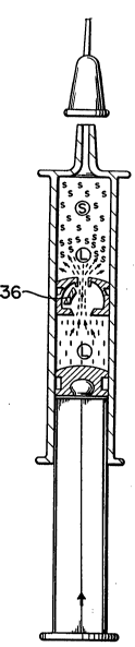
40 Referring to Figure 1 of the drawings, a preferred embodiment of the present
invention is shown, which is a pluro-compartment storage/mixingldispensing
syringe, with withdrawal test capacity, wherein admixing and dosing of
medications or other mixtures is effected.
~ C
2016870
The said syringe has a longitudinally and rotationally symmetric main barrel
1, uniform and free of radially inward protrusions, open distally and
proximally by apertures 2 and 3, and whose inner barrel wall 4, confines
both fluids, solids and mixtures thereof.
Barrel 1 which maybe constructed of glass or plastic materials, wherein
glass is used to effectuate longer term storage requirements, may for
example, be easily molded from inert transparent plastic such as injection
molded polypropylene. Polypropylene carries substantial benefit like
o resistance to practically all solvents and medication, low water loss and
resistance to sterilization procedures. As seen the barrel 1 has a uniform
inner surface free of radial protrusions for smooth operation.
The distal extend 5 of barrel 1 is tapered to a tip 6, to which a hypodermic
Is needle 7, cannula or other suitable conduit may be connected by means of
needle or conduit connecting means, such as a luer connector already
known in the prior art. The said distal tapered extent 6 comprises a distal
and central aperture 2, through which expulsion of mixture may be effected.
20 The syringe has a closure capability in a flexible attached cap 9 (Figure 19)or a molded break-away resilient tip 10 (Figure 20), releaseably connected to
the tapered tip 6 thereby facilitating an air/fluid-tight seal.
At its proximal most extent, the barrel 1 has either a circumferential grip or
25 flared finger grips 11 to facilitate holding and activation of the syringe.
Moreover, at least 2 distally flared finger grips 12 ~Figures 1 and 15) may be
included near the tip 6 to facilitate injection, where a slightly increased
resistance to expulsion may be encountered due to the presence of both,
30 internal stopper 14 and plunger 13. Nevertheless, the injection stability is
improved by the distal grips which have primary importance when close
proximity to the needle is required for stable hazard-free injection such as in
application to animals in Veterinary Medicine. In the latter, the syringe
should be held by the tripodal flared distal finger grips 12 ~Figure 16) close
3s to the injection site, with the plunger shaft grip 15 placed against the palmof the hand of the user in a way that simultaneous counter motion of the
palm and fingers results in e~pulsion of mixture. Alternatively, the syringe
barrel may have a raised and roughened finger grip area 16 (see Figure 17).
40 Into the proximal aperture 3 of barrel 1, a plunger 13 is fitted in a sliding manner. Said plunger is composed of elastometric material such as
medical/pharmaceutical grade rubber and has a diameter slightly larger than
the inner diameter of barrel 1. Moreover, the plunger is disposed in an
airtight, fluid-tight sealing relation with the inner barrel wall 4 and said
.
:., :~. . ., ' -
2016870
plunger has at least two axially spaced ridges 17, separated by a sulcus 18
to maximize the sealing sliding relationship by virtue of a flexible double
seal.
s Said plunger is convexly curved 19 (Figure 1 ) distally so as to apply maximalpressure to the contained fluid column upon axially distal advancement and
to permit a more complete evacuation of the substance in the barrel by
conforming to the distal terminal inner barrel 20.
o In another embodiment, plunger 13 comprises a distal tip 21 ~Figure 13) to
accommodate a proximal blow plug valw stopper aperture 22 (Figures 1 - 5)
in a male/female interaction so as to minimize residual volume in said
stopper central cavity 23 (Figures 1 - 5).
15 Plunger 13 can receive in a male/female interaction, a tripodal plunger shaft24, which by virtue of its tripodal nature economizes material usage and
maximizes shaft strength, affixed thereto by a distally dilated projection 25.
Said projection is snapped or screwed into a lipped aperture ridge 26 in the
the proximal plunger body 13.
Plunger shaft 24 could be preassembled or deployed at the time of usage in
a single step, to minimize potential for accidental deployment. If the plunger
is deployed, the insertion and depression of the plunger shaft axio-distally
results in plunger attachment, mixing of the components inside the barrel 1
2s and finally, dispensation.
A safety locking clip 27 could be included to prevent accidental depression
of the plunger and the dispensation of mixture. Said clip should be
removeably fitted across proximal finger ~qrip 11 and shaft finger grip 15 so
30 as to immobilize the plunger shaft 24.
A flexible pop-out blow plug valve seal stopper 14, made of rubber, rigid or
elastometric material of low chemical reactivity, is positioned axially and
slideably in an airti~ht, fluid-tight engagement into the barrel 1, between the
3s distal extent 20 and the proximally inserted plunger 13. Proximal
compartment 28 and distal compartment 29 are thus formed and confine
their contents into the inner barrel wall 4; the stopper may be placed at
any position relative to distal barrel extend and proximally inserted plunger.
40 The first proximal content is usually a liquid (L) or diluent and the second
distal content a powder, solid ~S) or Iyophylized powder in the event of
vaccines. The distal compartment 29 includes an air space to accommodate
the rapidly entering fluid upon the establishment of a communicating
pathway between compartments 28 and 29, the so called fluid burst.
"~
. . . :
2016870
12
Said stopper 14 has a radially uniform elastic circumference 30 ~Figure 6)
and a curved distal extent 31 (Figure 4), thereby exerting maximal
dispensation force upon depression of the plunger and wherein said stopper
s is of slightly larger diameter than the diameter of inner barrel 4. The stopper
14 is thereby disposed in fluid-tight relationship with the barrel 4, said
relationship being maximized by the stopper axially spaced ridges 32 and 33
separated by a sulcus 34. The proximal ridge 33 may be enlarged so as to
increase stopper barrel contact area and effect maximal resistance to
10 movement until the time of advancement of said stopper into a fluid
containing area with subsequent lubrication of stopper circumferential
leading edge and diminution of its coefficient of resistance at said edge.
Stopper 14 is characterized by a hollow dilated central cavity 23, open
15 proximally and distally by stopper apertures 22 and 35 respectively. The
proximal aperture 22 is releaseably sealed by a releaseably connected
pressure activated blow plug 36, which by the nature of its releasability acts
as a valve, being so arranged as to be preferentially responsive to pressure
and force conditions from the proximal side thereof to form a communicating
20 pathway between compartments 28 and 29 as a result of distal deflection of
said blow plug 36 into the central cavity 23, thereby allowing bypass flow
of liquid from compartment 28 through the proximal stopper aperture 22,
through the central cavity 23, by the blow plug 36, through the distal
stopper aperture 35 into compartment 29 to effect admixing of material
25 contents (Figure 3).
Said force effected by pressing plunger 13 distally and axially into the barrel
4, engages the stopper, initiates unisomous movement of said stopper, fluid
and plunger, and dispensation of mixture from the needle (Figures 2 -3).
A preferred embodiment of the stopper blow plug 36 is characterized by a
concave proximal face 37 and diameter smaller than the stopper 14
diameter. The blow plug 36 is releasably bonded or fitted into the proximal
stopper aperture 22, utilizing differential coefficients of friction or releasable
35 bonding. Improved force of transmission is effected from plunger 13 to
liquid (L), to blow plug 36, when the blow plug has a maximal proximal
surface area. Additionally, by virtue of the flexibility resulting from the
hollow stopper cavity 23, the stopper 14 may aid in the release of the blow
plug 36 owing to deflection of the proximal stopper wall 38 (i.e. the
40 rearward end wall); the stopper by virtue of its flexibility and elastomeric
properties aids in the preferential dislodging of said blow plug. j `
Sleeves 39 (Figures 10 - 11) of hardness and coefficient of friction different
from the materials constituting the stopper 14, may be inserted between the
~;c ~ f - -
,, , , . ., -
.
..
- ' ' ' '
- ,- .. , ~ . .
2016870
I3
blow plug 36 and the proximal stopper walls 38 to provide different
resistance and preferential movement of the blow plug 36 and/or said
sleeves (over movement of said stopper). Moreover, the sleeves and/or
blow plug 36 could be tapered e.g. be conical to effect ease of activation.
s
Additionally, the ratio of stopper 14 axial length, in comparison to blow plug
36 diameter, and thickness maybe such that the frictional resistance of blow
plug 36 toward force conditions in compartment 28 is preferentially
overcome before that of said stopper 14, thus allowing admixing by opening
o of the blow plug valve 36 before movement of said stopper 14. If the said
ratio is a limiting factor, a zone of increased frictional resistance along the
inner barrel wall 4 may be provided to effect said movement of blow plug 36
preferentially to stopper 14.
The stopper 14 further comprises a catch means to entrap the blow plug 36
within the central cavity 23 and consists of internal distal stopper aperture
catch tabs 41 which hold the blow plug within central cavity 23 during
admixing and dispensation of mixture. The distal stopper aperture 35 is
defined by the forward axial end wall of the cavity 23. The distal stopper
20 aperture 35 is defined by the forward axial end wall of the cavity 23.
It should be noted that the distal stopper aperture 35 (Figure 8) could be
skewed laterally thereby allowing the distal inner stopper wall 42 to act in a
catch means fashion.
Figure 12 shows an alternative embodiment that utilizes a blow plug 36
anchored by a blow plug anchor 43 to preclude movement of said blow plug
36 into compartment 29 while still allowing withdrawal test capabilities and
bypass flow.
Blow plug 36 may also be releaseably positioned at the distal stopper
aperture 44 ~Figure 9) and either activated by pressure force exerted by
plunger depression and resultant distal expulsion or by vacuum created by
proximal plunger 13 withdrawal. In the latter case, the blow plug 36 is
35 pulled into stopper central cavity 23. This vacuum activation applies also to proximal aperture insertion of the blow plug 36.
To those skilled in the art, it will be apparent that stopper 14 is
advantageously adaptable to any standard syringe barrel and by variance of
40 the relative position of said stopper 14 with respect to the distal barrel
extend 20 and proximally inserted plunger 13 can create advantageously
compartments 28 and 29 of various sizes.
":
,
- 201~870
It should be understood that the foregoing relates to only a preferred
embodiment of the invention which has been shown by way of example,
and that it is intended to cover all chanyes and modification of the example
of the invention herein chosen for the purpose of the disclosure which do
s not constitute departures from the spirit and scope of the invention.
2S
, ;~ : . , `,