Note: Descriptions are shown in the official language in which they were submitted.
~~ ~ ~~ ~. !~
~~,cR~~our~n o~ T~~ xrav~~zorr
~~~~.a a~ th~ xnv~~,tio~
'his invention relates to antennas and, more
particularly, to a novel, inexpensive, and highly-
effective antenna that has nearly constant gain over a
hemisphere of solid angle so 'that it is essentially
omnidirectional for antennas located near the surface of
the earth. It is sensitive over a wide bandwidth and,
compared to other inexpensive antennas, such as turnstile
and patch antennas, has an improved impedance match and
voltage standing wave ratio (VSWRj.
Descx is ~t on o,~, tie ~r . r ar+.
For certain radio transmissions, circular
polarization (CP) is desirable. CP is a special case of
elliptic polarization in which the horizontal and
vertical (orthogonal] components are of equal magnitude
and exactly g0 degrees out of phase. Most polarized
signals are not perfectly circular, but have same degree
of ellipticity. References herein to CP~include elliptic
p~larization in every possible range.
Turnstile, patch, and other types of relatively
inexpensive antennas are known that are semi-
omnidirectional --i.e., have nearly uniform gain over the
celestial hemisphere seen from a point relatively near
the surface of the earth--and have respective impedances
that can be matched to those of the respective circuits
in which they are used. Turnstile antennas are disclosed
in a book entitled "Antennas" by 3ohn D. Kraus, McCraw-
Hill hook Company, second edition, 1988, pages 726-731,
A typical conventional turnstile antenna 10 (Fig. lA of
the appended drawing) comprises two dipoles 12 and 14
lying in a plane. Such an antenna is referred to
hereinafter as a ~~planar turnstile.o' If the dipoles 12
and I4 are properly related to each other and properly
driven and the plane defined by the dipoles 22 and 14 is
horizontal, the turnstile antenna formed thereby can
transmit or receive CP radiation very well ~t the zenith,
which is directly above the antenna, but less well as the
angle from the zenith increases.
Another well-knot semi-omnidirectional antenna
is commonly referred to as a '~patch,~o or planar
microstrip antenna, These antennas are also disclosed in
the Kraus publication mentioned above (pages 745-749).
With this type of antenna, the reduction in the vertical
K-field component is even more pronounced, resulting in a
severe loss of axial ratio for circularly_polarized
signals in the plane of the horizon. A typical
microstrip patch antenna is shown in Figs. 1.8, 1C and 1D.
An example of this effect is shown in Fig. 2.
I~ this figure, where the angle is defined bar a line from
the zenith x to the antenna 10 and another line from the
antenna ZO to a point 16 displaced from the zenith, the
component of the E vector in the vertical direction is
reduced: and where the angle is 90°.--that fs, where the
angle is defined by a line from the zenith to the antenna
IO and another line from the antenna 10 to a point 18 on
the horizon--, the vertical component of the E vector
_3_
disappears entirely in the case of the patch and nearly
so in the case of the turnstile, sa that the radiation is
no longer circularly polarized. Thus a conventional
patch antenna and to a lesser extent a conventional
turnstile antenna mounted with its bass plane horizontal
to achieve hemispherical omnidirectionality does not
effectively radiate or receive circularly-polarized
radiation to or from a region lying in a direction
from the zenith. As Fig. 2 shows, the vertical component
of the E vector decreases to nearly zero in this region.
As the angle with respect to the zenith increases, the
axial ratio deteriorates markedly, so that the
conventional patch and turnstile are reduced to
functioning essentially as linearly-polarized antennas.
~n some applications, this loss of axial ratio
(or reduction from circular polarization to linear) can
mean a significant loss in system performance. For
example, in the case where a signal from a navigation
satellite is incident at a very lnw elevatian angle above
the horizon (80° or more of off-axis angles from the
zenith) on a receiver mounted an a marine vehicle, there
are likely to be significant ~nulti-path reflections from
the surface of the water. When the receiving antenna is
able to receive only a single, horizontally-polarized
signal, it is likely that interference due to the
anultiple paths will induce severe fading of the signal,
resulting in a loss of information. With an antenna that
has good circular polarization (CF), however, the degree
of fading is significantly reduced, since it is aauch
harder to cancel out both the vertical and horizontal
compon~ants with precisely the right 90-degree phase shift
between the two signals. In other words, good CP vastly
alleviates the problems of low look-angle reception.
Conventional patch and turnstile antennas
moreover do not provide uniform gain over a solid angle
of lso° of celestial arc. Essentially constant azimuthal
gain in the plane of 'the horizon is easily achieved by
using twa pairs of dipole elements arranged at right
angles to each other. However, such an antenna provides
more gain in a direction normal to the ground plane than
in a direction parallel to the ground plane. This is a
disadvantage particularly on moving vehicles (boats, for
example) that exhibit roll and pitch in addition to yaw
and translation and that need to transmit or receive
omnidirectionally over the celestial hemisphere.
For example, consider a conventional patch or
turnstile antenna mounted on a boat that is moorad in
quiet wat~rs or is in a yard or dry dock. For bast
omnidirectional transmission or reception over the
celestial hemisphere, such an antenna will be mounted
with its ground plane parallel to the harizon and its
mast extending in a direction normal to the plane of the
horizon. The gain o~ the antenna will then be as shown
in curve A o~ Fig. 3s namely, it will range from a
typical maximum value at the zenith, shown in Fig. 3 as
+5 decibels relative to isotropics (dBi), to a greatly
reduced value on the horizon, shown in Fig. 3 as about -5
dBi.
-5-
~~~<~d~:l.~~
het it be assumed that this is Satisfactory for
reception of signals from, say, a navigation satellite
that is anywhere above the horizan. Been on that
assumption, reception of signals from a navigation
satellite that is low above the horizon may be
unsatisfactory at sea, where the boat is subject to roll
and pitch. For example, suppose that the satellite is 90°
off the starboard bow and low above the horizon while the
boat rolls to port. Tha ground plane of the antenna,
which is fixed relative to the boat, will also roll to
port, thereby correspondingly reorienting the curves of
Fig. 3 so that the antenna gain will fall from the -5 dBi
it provides when the boat is level (curve ~,, which
relates to a conventional antenna) to a value less than
that, which may be insufficient for adequate transmission
or reception.
The situation is made worse when two boats
communicate with each other using conventional semi-
omnidirectional turnstile antennas. Frora time to time
they will roll and pitch in such a way that the antenna
masts tilt away from each other. In that case, the
curves of Fig. 3 relating to the transmitting antenna
will be rotated, say, clockwise, while the curves for the
receiving antenna will b~ rotated counterclockwise. Thus
a signal that is weaker because of the roll and pitch of
one boat has to be detected by an antenna that is less
sensitive because of the roll and pitch of the other
boat.
-6-
dBi.
-
Another problem witty canventional patch
antennas is that they are narrow-bandwidth devices that
must be carefully tuned to achieve satisfactory operation
at the desired frequency. This increases the complexity
and cost of the impedance-matching tuning that is
necessary to compensate for variations in materials, etc.
A primary factor in getting a good SNR is the noise
figure of the preamplifier. The antenna is usually tuned
to get the best noise figure for nominal preamplifier
impedance. Sut if the antenna has a narrow band, it is
hard to guarantee that its impedance will be close to the
nominal value at the correct frequency.
Another problem with conventional turnstile
antennas is that separate mechanical and electrical
structures are provided, thereby leading to undesirable
complexity and unnecessary cost. Tn particular, the mast
(mechanical structure) supporting the dipole elements and
the driving balun electrical structure) are physically
separate, as disclosed for example in a patent to
Counselman et al. No. 4,647,942.
Various attempts have been made to avercome the
problems of conventional turnstile antennas noted above.
The most notable is a drooping dipole arrangement
disclosed by a patent to Woodward et al. No. 4,062,019.
This device has radiating elements attached to mast at a
45-degree angle to the mast. The dipole elements droop
down from their point of attachment in a straight line.
The radiating element is thus at a 45-degree angle to
both the plane of the horizon and a vertical plane
-7_
thraugh the mast. This inclination of the radiating
elements makes it possible for the two orthogonal
components of the electric field to exist over a much
wider range of solid angle. In the case of planar patch
and turnstile antennas (see Figs. lA-1D}, the vertical
component of N field in the direction of the horizontal
plane (the ground plane) is significantly reduced as
explained above.
So the Woodward et al, drooping turnstile
antenna, addresses some of the needs of a small, simple,
semi-omni/CP antenna. Tts most important characteristic
is that the dipole elements are all straight lines,
inclined at a 45 +/-5-degree angle to the mast of the
turnstile. In addition, the characteristic impedance of
the drooping dipole is a fixed number that must be
accounted for in the impedance matching network.
(Naturally it is variable over a certain range dictated
by dipole physical dimensions, spacing with respect to
the ground glane, etc., but the range of variation is
small.)
Other prior art of interest includes the
following U.S, patents: 1,988,434, 2,110,159, 2,976,534,
3,919,710, and 3,922,683. FIowever, no art heretofore
developed discloses an inexpensive antenna that has
essentially constant gain over a hemisphere of solid
angle so that it is semi-omnidirectional, has excellent
CP near the horizon, and is sensitive over a wide
bandwidth and has an excellent VSWR.
-8-
CA 02026148 1999-06-04
OBJECTS AND SUMMARY OF THE INDENTION
An object of the invention is to remedy the
problems outlined above. In particular, an object of the
invention is to provide a novel, inexpensive, and highly-
effective antenna that has essentially constant gain over
a hemisphere of solid angle so that it is semi-
omnidirectional.
Another object of the invention is to provide
an antenna with excellent CP over a wide range of look
angles, especially near the horizon.
Another object of the invention is to provide
an antenna that is sensitive over a wide bandwidth and
has an excellent impedance match and VSWR.
Another object of the invention is to provide
an antenna that requires no tuning or is easily tunable
without the aid of special circuit elements such as
impedance-matching transformers, which are unavoidably
lossy.
The invention therefore provides an antenna
comprising:a base plate defining a ground plane; a mast
for conducting electrical feed current, said mast being
attached to the base plate and extending along an axis
that is normal to the ground plane;a first pair of
antenna elements defining a dipole conductively coupled
to the mast at a first end and each of said antenna
elements having a second end substantially closer to the
ground plane than to said first end and being formed
-g-
CA 02026148 1999-06-04
together with first respective portions of dielectric
material; each of the first pair of antenna elements
exhibiting a smooth and continuous first curvature
throughout its length in a plane containing the mast;
and a second pair of antenna elements defining a dipole
conductively coupled to the mast at a first end, each of
said antenna elements of said second pair having a second
end substantially closer to the ground plane than to said
first end and being formed together with second
respective portions of dielectric material: each of the
second pair of antenna elements exhibiting a smooth and
continuous second curvature throughout its length in a
plane containing the mast; characterized in that a first
pair of conductive tabs is provided, each connected to
said base plate, one of said first pair of conductive
tabs being connected to one of said first portions of
dielectric material in closely spaced apart relation to
said second end of one of said first pair of antenna
elements and the other of said first pair of conductive
tabs being connected to another of said first portions of
dielectric material in closely spaced apart relation to
said second end of the other of said first pair of
antenna elements; and a second pair of conductive tabs is
provided, each connected to said base plate, one of said
second pair of conductive tabs being connected to one of
said second portions of dielectric material in closely
-10-
CA 02026148 1999-06-04
spaced apart relation to said second end of one of said
second pair of antenna elements and the other of said
second pair of conductive tabs being connected to another
of said second portions of dielectric material in closely
spaced apart relation to said second end of the other of
said second pair of antenna elements.
BRIEF DESCRIPTION OF THE DRAWINQ
A better understanding of the objects, features
and advantages of the invention can be gained from a
consideration of the following detailed description of
the preferred embodiments thereof, taken in conjunction
with the appended figures of the drawing, wherein:
- 10a -
r~'~.~~I~~3~i_~:~
Fig. lA is a perspective view of a conventional
planar turnstile antenna;
Fig. 1B is a plan view of a conventional. patch
antenna illustrating a shape that is nearly but not quite
square (L1 > L2) and a coaxial input located on a
diagonal of the patch offset from the canter thereof;
Fig. 1C is a side view of the structure of
Fig.lBt
Fig. li7 is a plan view illustrating the
connection of the patch of Figs. 1B and 1C to a branch
line hybrid in a microstrip;
Fig. 2 is a perspective view of a turnstile
antenna illustrating its ability to transmit and receive
electromagnetic radiation that is circularly polarized as
a function of the angle formed by a first line extending
from the zenith to the antenna and a second line
extending through thg antenna in a direction parallel to
the direction of propagation of the electromagnetic
radiation;
Fig. 3 is a diagrammatic view in elevation
showing the antenna gain in dBi as a function of the
direction of propagation relative to the horizon (or
zsnith) in the case of a typical conventional turnstile
antenna (curve A) and in the case of an antenna
constructed in accordance with the invention (curve B);
Fig. 4 is a diagram showing different
curvatures in accordance with the invention oi' a dipole
element with n as a parameter in the equation
4 ~ a y
a b
e~l~
~~~~~~r.
which equation represents a subset of all possible curves
in accordance with the invention;
Fig» 5 is a top plan view of a base plate that
defines a ground plane in an antenna constructed in
accordance with the invention;
Fig. 6 is a top plan view of a printed circuit
board that supports two pairs of dipole elements and is
used in constructing an antenna in accordance with the
invention;
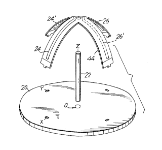
Fig. 7 is an exploded perspective view showing
the assembly of the structures of Figs. 5 and 6 together
with a coaxial cable that serves as a mast in order to
form an antenna in accordance with the invention;
Fig. 8 is a perspective view of an assembled
antenna in accordance with the invention;
Fig. g is a perspective view of the antenna of
Fig. 8 with the addition of passive dipole elements
forming parasitic-coupled resonators in accordance with
th~ inventaon;
Fig. 10 is a view corresponding to Fig. 8 but
showing the replacement of the quarter-wave dipole
eiements of Fig. 8 with half-wave dipole elements
connected to the ground plane;
Fig. 1~. is a graph of the return loss in vSWR
as a function of frequency in the case of a conventional
patch antenna. and
Fig. 1~ is a graph of the return loss in VS'6~
as a function of frequency in the case of an antenna
constructed in accordance with the invention.
_lZ_
l~~~i~i~=~.~~
o~sca~~~T~aer o~ T~ ~E~~ ~n o r~ rr
Fig. 8 shows a preferred embodiment of an
antenna constructed in accordance with the invention. It
comprises a base plate 20 forming a ground plane, a mast
22 connected to the base plate 20 and extending along an
axis that is normal to the ground plane, and a pair of
dipole elements 24 and 26 (the latter hidden in Fig. 8
but visible for example in Fig. 5) together forming a
first dipole and each having a first end 28 or 30
connected to and supported by the mast 22 at a first
location spaced apart from the ground plane by a
predetermined distance (e~aal to the height of the mast
22) and a second end 32 or 34 closer to the ground plane
(i.e., touching the ground plans (Fig. 20) or spaced
apart from the ground plane (Fig. 8) by a distance less
than the predetermined distance).
In accordance with the invention, each of the
dipole elements 24 and 26 exhibits a curvature in a plane
containing th~s mast 22.
In order to obtain circular polarization and an
antenna gain that is essentially constant azimuthally
with respect to the ground plane, an additional pair of
dip~le elements 24' and 26' is employed, and the dipole
elements of the additional pair are cuzwed as described
above. Tn other words, the mast 22 lies along the
intersection of the planes defined by the curved dipole
elements 24, 26 and 24', 26'.
The curvature of the dipole elements may be
either convex, as indicated for example in Fig. ~3 and by
-18~
~~~%j~~.;~fy
~ ?.~ .~.
curves n ~ 2 and n ~ 1Q in Fig, 4, or cancave, as
indicated by curves n = 0.5 and n s ~D.7 in Fig. 4.
Convexity and concavity are defined with reference to the
perspective for example of Fig. 8, which shows the
antenna as it might appear when held in the hand.
As Fig. 9 shows, the invention preferably
further comprises a pair of elongate parasitic elements
36 and 38 respectively cooperating with the pairs of
dipoles 24, 26 and 24', 26' and each exhibiting a
curvature in a plane containing the mast 22. The
parasitic elements 36 and 38 may lie respectively in the
planes of the dipole elements 24, 26 and 24', 26' or may
be rotated about the axis defined by the mast 20 so as to
lie in different planes from the planes of the dipole
elements 24, 26 dnd 24' and 26°. The parasitic elements
36 arid 38 may but need not be respectively generally
parallel to the dipole elements 24, 26 and 24', 26'.
The base plate 24 forms a ground plane XY (Fig.
5) defined by axes X and Y that intersect each other at
right angles at an origin o. The mast 22~is connected to
the bass plate 20 at the origin 0 and ext~nds along an
axis Z (Fig. 7) that is normal to the ground plane XY at
the origin Q. The dipole elements 24, 26 extend in a
plane XZ defined by the axes X and Z. The dipole
elements 24', 26' extend in a plane YZ defined by the
axes Y and Z. Each of the dipole elements 24, 26 and
24', 26' exhibits a curvature in the XZ plane or YZ
plane. This curvature has a first derivative that is
-14-
continuous and has a constant sign, In the case of the
dipole 24, 26, the curvature is given by
j
a b
where x is distance from the origin 0 along the X axis, z
is distance from the origin 0 along the Z axis, a and b
are arbitrary constants, and n is a parameter such that 0
< n < ~ and n ~ 1. In the case of the dipole pair 24',
26°, the curvature is given by
~m
a b
where y is the distance from the origin 0 along the Y
axis and the other symbols have the same meanings as
those set out aibove.
Ntoreover, in accordance with the invention, the
mast 22 is formed by a coaxial cable feed. As Fig. 8
shows, the center conductor of the coaxial cable feed,
for example the conductor 40, is connected to two of the
dipole elements that meet at right angles, for example
the elements 24 and 24' (the latter being hidden in Fig.
8), and the other conductor of the coaxial cable feed,
for example the outer conductor 42, is connected to the
other dipole elements, for example, the elements 26
chidden in Fig. 8) and 26'e The ratio of dipale lengths
D'/DZ is approximately edual to 1.17. The dipole lengths
are different in order to provide circularly polarized
waves with a single feed.
The dipole elements 24, 26 and 24°, 26' are
preferably formed as part of a printed circuit board. A
fiberglass board 44 (Fig. 6) 0.01 inches in thickness and
_1~_
shaped as a cross has the dipole elements 24, 26 and 24',
26' fonaed thereon. Adjacent orthogonal dipole elements
are printed on opposite sides of the thin cross. This
facilitates making connections to the coax/raast. At
their outer ends, the dipole elements tray but need not
terminate short of conductive tabs 46, 48, 50 and 52 of
the same width as the crossed arms of the fiberglass
board 44. The tabs 46, 48, 50 and 52 are formed with
projections 54, 56, 58 and 60, that can be inserted
respectively through holes 62, 64, 66, 68 formed in the
base plate 20 {Fig. 5). The holes 62, 64, 66, 68 are
spaced from a center hole 70 for the mast 22 by a
distance which is selected relative to the lengths of the
arms of the fiberglass board 44 and the height of the
mast 22 so that, when the projections 54, 56, 58, 60 are
inserted through the holes 62, 64, 66, 68 and the mast 22
is properly positioned, the arms of the fiberglass board
44 and therefore the dipole elements 2~, 26 and 24', 26'
are automatically given the desired curvature.
Fig. 7 is an exploded view showing the mast 22,
the fiberglass board 44, and the base plate 20 in a
position about to ba assembled, and Fig. 8 shows the
final assembly. Fig. 9 shows the addition of the
parasitic resonators 36 and 38, which modify and in
general enhance the curve ~ shown in Fig. 3. As curve
shaves, the antenna gain is about +3 dBi at the zenith and
about -2 dHi at the horizon. While some gain is
sacrificed at the zenith as compared to curve A of a
conventional antenna, this is of no consequence, since at
-16-
the zenith the incoming signal from a navigation
satellite, for example, experiences the least attenuatian
and distortion. What is important is that, near the
horizon, antenna gain is considerably improved relative
t~ the gain of the conve.ntionai turnstile. Moreover, in
accordance with the invention, signal gain remains nearly
the same even at angles somewhat below the horizon. Thus
transmission and reception are not compromised even when
a boat or aircraft, etc., on which the antenna is mounted
rolls and pitches through a considerable angle.
The direction of the curvy (either inward,
toward the mast and ground plane or outward, away from
the mast and ground plane) alters both the impedance and
the radiation pattern. The best arrangement for
obtaining good impedance matching, excellent gain pattern
and excellent circular polarization (axial ratio) is
achieved when the dipole elements are curved in a manner
resembling the spokes of an umbrella. The preferred
embodiment of the invention may therefore be described as
an "umbrella" antenna. Since the curve of each dipole
element is within a plan~ containing the coaxial mast,
ther~ is no spiral component, which would make the shape
of the dipole element three-dimensional. ~n the
equations set out above and in Fig. 3, when n ~ 1, we
have the familiar, degenerate case of a straight--line
dipole element, described in the Woodward et al. patent
mentioned above. As n increases in value, the curvature
becomes convex (pushed outward toward the viewer). When
n equals 2 and a and b are equal, we have a circle, and
-17-
s~ ~'. 1 ~, . tp
l~a~;~_~.1~~
the preferred umbrella dipole element appears. As n
increases, the curve begins to look more like a
rectangle. When n is less than 1, the dipole element
begins to droop downward and becomes concave (pushed
inward, away from the viewer), as shown by the examples n
= 0.7 and n ~ 0.5. The allowable range fox n is any
value greater than 0 (except n = 1, the condition that
results in linear dipole elements). The preferred range
is less, and, in accordance with the best-known mode of
practicing the invention, n ~ ~.
When a and b are equal and n g 2, the curves
are circular, as noted above; when a and b are unequal
and n = 2, the curves are elliptical.
It is not necessary for the dipole elements to
touch the base plate forming the ground plane (Fig. 10)
but only come near it (e. g., Fig. 8). The mast to which
the dipole elements era attached can touch and penetrate
the base glate in order to provide the support needed and
provide a connection from the mast/coax to the rest of
the transmitter/receiver (not shown).
Ths curvature of the dipole elements in such a
manner as to have a continuous first derivative with a
constant sign affords two advantages previously
unavailable to the designer. The first is that the
characteristic impedance of the dipole and therefore of
the entire assembly can be made to cover a very wide
range. The second is that the radiation pattern of the
dipole and therefore of the entire assembly, when used as
an array to form an antenna of practical value, changes
-1~-
c'S c' ~a . r7
considerably because of the varying spatial relation of
the dipole to the ground planra.
The antenna can be connected to a transmitter,
a receiver, or both. When connected to both, it is
through a combining junction. In the case of the
receiver, it is important to be able to achieve the exact
impedance match necessary to get the best overall
receiver performance as determined by a system figure of
merit, normally given by the ratio of antenna gain G to
system noise temperature T or G/T. It can be shown that
the detected SNR is directly proportional to this
commonly-employed figure of merit. Often it is difficult
to obtain the desired impedance levels directly from the
antenna elements. Instead, various impedance-matching
techniques are employed, using various types of
transmission lines or transformers. These impedance-
matching circuit elements often introduc~ resistive
losses that decrease the affective gain G of the antenna.
So it is significant that the impedance level of the
antenna of the invention can be varied over a wide range.
The preferred embodiment of the invention achieves a
desirable impedance level and maintains it over a wide
frequency range.
Similarly, when the antenna is being used as a
transmitter, it is equally impartant that the antenna
impedance be matched to the source impedance for maximum
power transfer. So regardless of use, the ability to
vary the impedance levels is a major advantage not easily
obtainable with comparable turnstile configurations.
-19-
When the curvature of this dipole elements
approximates that of a circle (n = 2), the resultant
characteristic impedance is brought into a region where
it is optimum for achieving the best noise figure from
the receiver amplifier, and therefore the best receiver
figure of merit G/T. The tuning and impedance matching
can be accomplished without use of lossy transformers or
additional circuit elements. The shape of the dipole
elements moreover makes it relatively easy to fabricate a
usable antenna.
In the preferred embodiment, the mast or
support structure for the dipole elements is made up of
the coaxial feed line, a semi-rigid outer tubing commonly
used in the communications industry and having a standard
0.141-inch diameter. The mast actually functions as a
balun, or balanced-to-unbalanced transformer, which is
needed in order properly to convey energy to or from the
dipole elements, It is approximately a quarter-
wavelsngth (open-circuit case) or a half-wavelength
(short-circuit case) in height above the ground plane and
thereby performs the balanced-ta-unbalanced conversion
process.
Circular polarisation is obtained with the
umbrella antenna by the method described in the Woodward
et al. patent. The dipole elements in the ~tZ (or YZ)
plane are made to be slightly shorter than they would be
if they were truly resonant at the desired operating
frequency. The dipole elements in the YZ (or XZ) plane
are made to be slightly longer. This separation of
-20-
f1 ~ K~ ~5 . ~ (l
resonant frequencies provides the mechanism for obtaining
the 90-degree phase shift needed to form a circularly-
polarized signal. At the operating frequency, the phase
of the longer dipole leads the phase of the shorter
dipole. By adjusting the lengths, the desired 90-degree
shift can be obtained. This method is well known and is
used extensively in patch and other antenna designs.
At the feed point, i.e., at the top end of the
mast, there are four dipole conductive elements forming
two orthogonal dipole pairs. Ons adjacent pair is
printed'on the top side of the dielectric cross and the
other is printed on the bottom side (Fig. 6). The inner
end (i.e., the end near the mast) of a dipole element of
one dipole pair is connected to the inner end of a dipole
element of the other pair on the top side of the support
dielectric, and the two elements thus connected are
connected to, say, the center conductor of the caax
forming the support mast. similarly, the inner ends of
the two remaining dipole elements on the bottom side of
the support dielectric are connected to each other and to
the other (outer) conductor of the coax forming the mast.
Thus adjacent orthogonal pairs of dipoles elements are
driven in a balanced manner, exactly as they must be in
order properly to excite the dipoles. The drawings
illustrate structure that produces left-hand circular
polarization. By reversing the connections between
adjacent orthogonal dipole elements, the sense of the
polarization can be reversed (from left to right).
~,~~~~:~.~1~
The type of dipole used for the radiating
element can ba either open-circuited, as in the preferred
embodiment as shown in Figs. 6-9 of the drawing, or
short-circuited, as shown in Fig. 1o. Tn the short-
circuited embodiment of the invention, the end not
connected to the mast-balun is connected to ground
electrically. In this case, it is preferably about a
half-wavelength long instead of a quarter-wavelength for
the open-circuited case.
Parasitic resonators are used in the so-called
Yagi antennas (for reception of television signals) to
provide a change of pattern from that of the basic
dipol~. These parasitic resonators often have the same
general shape and nearly the same size as the active
dipol~. In a similar manner, it is possible to alter the
far-field pattern of the basic antenna in accordance with
the invention having two pairs of dipoles by providing a
set of parasitic resonators whose general shape mimics
that of the active elements. These parasitic re:~onators
can be arranged either to enhance the gain on-axis, at
the local zenith, or to °~squash" the pattern and provide
an increase in gain in the plane of the horizon, at the
expense of gain in the zenith direction. Further, these
parasitic elements can be aligned in any azimuthal
direction in the ~Y plane.
The equations set out above by no means
represent the only curves that can be used to define the
shape of the dipole elements. The equations are very
-
good, hawever, for representing near-right-angle bends,
as n approaches infinity.
The twa halves of each dipole need not be of
the same length. There may be some applications where,
say, the left half should be longer or shorter than the
right half or should depart from mirror-image symmetry in
some other way.
Moreover, the equations define the shape of
only one-half of a complete dipole pair: i.e., the shape
of only a single resonant element. if the same equation
is applied to both elements of a dipole pair, the
derivative undergoes a sign change at x = 0 or y ~ 0.
One of the most important benefits of the new
antenna design in comparison to a planar patch antenna is
that the frequency bandwidth over which a very good
impedance match can be obtained is much larger. For
example, a typical planar patch might exhibit a voltage
standing wave ratio (VSWR) vs. frequency plot as shown in
Fig. 11, for an antenna operating at a frequency of 1575
MHO. By contrast, the umbrella antenna exhibits a VSWR
vs. frequency plot as shown in Fig. 12. The acceptable
VSWR limit is arbitrarily chosen to be 1.92, or a return
loss of 10 dB. The bandwidth improvement, delianited by
points 1 and 2 in each graph, is over 400 percent. This
is typical of what can be expected from this new class of
dipole element. Because of the new degree of freedom the
curved dipole element provides, it is much easier to
obtain satisfactory performance.
-23-
s s'4 ,f~ , r~
The improvement in VSTnl~ vs> bandwidth is very
important from th~s manufacturability standpoint. ~t
means that less effort in the tuneup procedure is needed
to obtain a satisfactory level of performance, and
therefore the manufacturing cast can be less than in the
case of a planar patch. This is a benefit to
manufacturers and consumers.
Thus there is grovided in accordance with the
invention a novel and highly-effective antenna that has
nearly constant gain over a hemisphere of solid angle so
that it is essentially omnidirectional and circularly
polarized, that is sensitive over a wide bandwidth, and
that has an improved impedance match and VSWR. In the
foregoing disclosure and in the appended claims, terms
such as "normal, °' ''orthogonal," ''right angles," and
"parallel" relating one structure to another or to the
environment are employed. These terms are intended to
mean "generally," "roughly,°' or "substantially'° normal,
orthogonal, etc., and to allow for any degree of
tolerance that does not prelude the substantial
attaizuaent of the objects and benefits of the invention.
Many modifications of the preferred embodiments of the
invention disclosed herein will readily occur to those
skilled in the art, and the invention is limited only by
the appended claims.
--24--