Note: Descriptions are shown in the official language in which they were submitted.
. 7 ~ ~
-- 1 --
A21TIBIC)TIC LC)ADED JOINT PROST~ESIS
INTRODUCTION
.
This invention relates to a method of treating
an infected joint following total joint replacement. It
also relates to a prosthesis and a method of manufacturing
a prosthesis.
sACKG~OUND OF THE INVENTION
Infection following a total joint replacement is
an unavoidable complication affecting about 1.5% of
patients resulting in an estimated 3,000 cases per year in
North America alone. Eradication of the infection and the
joint reconstruction, preferably by reimplantation of
another joint, is important to a successful outcome.
Basically, three methods have developed in
dealing with this problem. The first is excision of the
joint, whereby the use of the limb is severely
compromised.
Secondly, there is a two-stage joint replacement
revision. With this method, the existing hip replacement
and all infected tissue ls removed. Antibiotic loaded
cement beads are placed in the femoral and acetabular
cavities and left there for a period of six to twelve
weeks until the infection has been eradicated. Once the
infection has been removed, a new total hip replacement is
implanted. The disadvantage of this method is that the
patient does not have normal use of the limb during the
interim period during which the infection is being
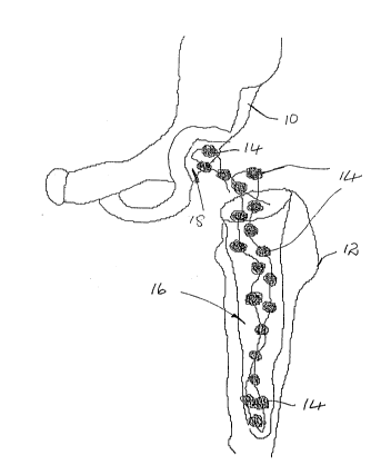
treated. This situation is illustrated in Figure 1 of the
accompanying drawings, where a patient's pelvic girdle 10
.
`; , ~
.. . .
:
. ,
.
:, ' '
~ J ~$ ~
-- 2
and femur 12 are shown wi~h anti~iotic loaded cement
beads 14 located in the femoral and acetabular cavities 16
and 18, respectively. Not only is the patient immobilized
during this period but hospitalization is also nacessary,
resulting in high medical expenses.
The permanent prosthesis which is *itted after
the infection has been removed is either cemented in
position or it is applied without cementing by forming a
press-fit with the femoral cavity. In the latter case,
the ~tem of the femoral component is provided with a rough
outer surface so that the bone can grow into the cavities
on the surface to bind with the prosthesis. In the case
of application of cement to the stem, the cement is
compressed into the interstices of the femoral cavity to
provide rigid fixation of the component.
The third method is a one-stage hip replacement ~ `
by which a permanent prosthesis is fitted directly,
without the intermediate step of the application of
antibiotic loaded bone cement beads. In this application,
the bone cement which is used to bond the psrmanent
prosthesis in the femoral cavity contains an antibiotic.
Thus, the permanent hip replacement is fitted directly
after the existing hip replacement and inPected tissue
have been removed. The bone cement is applied to the stem
of the prosthesis. The stem is then inserted into the
femoral cavity for bonding in the cavity.
There is mounting scientific evidence that the
two stage approach is more effective in eradicating the
infection and achieving an effective end result. But
despite the advantages of this method, the patient usually
remains immobilized and hospitalized for a period oP six
to twelve weeks.
' ' .: ~ . ,
' . : ', ' ,. ' ' '
,' ' ` , ' '. ' ' ~ ' "' '
~ ' . - ~ '
,~ - .
.'' . . ' " ' ' .
~ , .
J i.~ 3
-- 3 --
It is an object of the present invention to
provide a method and apparatus for treating a hip joint
infection which retains all the benefits of the two-stage
joint replacement revision but which avoids the
immobilization and lengthy hospitalization.
SUMM~RY OF T~E INVENTION
According to one aspect of the invention there
is provided a method of treating an infected joint
replacement which comprises the steps of removing the
original hip prosthesis and fitting a temporary
prosthesis, which comprises a femoral component provided
with an antibiotic loaded sleeve thereon in tha femoral
cavity of a patient, the femoral component being designed
with appropriate fatigue life and static strength based on
a life of about 12 weeks of normal activity of a p~rson
recovering from a total hip replacement. In this way, the
known interim infection treatment method by which a
patient was rendered immobilized and hospitalized is
replaced by the step of utilizing a temporary prosthesis,
which is not rigidly fixed in the femoral cavity, and
whilst serving to eradicate the infection, also serves the
useful purpose of providing the patient with the use of
the limb.
: .
~ lso aacording to the invention there is
provided a temporary prosthesis for use in the above
method, comprising a femoral component which is in the
Porm of an elongate endoskeleton having a neck portion and
a stem portion ad;acent to and at an angle to the neck
portion, the stem portion having a proximal end which is
ad~acent the neck portion and a distal end which is remote
from the neck portion and wherein the stem portion is of
~5 circular cross-section.
. .
.
.
,:
, , , . . , , , . , ., , -
;~ t~
Further according to the invention there is
provided a method of implanting a hip replacement in a
femoral cavity which comprises the steps of inserting a
mold in the form of a flexible lining into the cavity,
filling the mold with a bone cement, inserting the stem of
a femoral component down the femoral cavity into the bone
cement, allowing the bone cement and the mold to conform
to the shape of the cavity, allowing the bone cement to
solidify to form a composite component comprising the
femoral component and the sleeve on the stem thereof,
removing the composite component from the cavity, removing
the mold and reimplanting the composite femoral component
in the femoral cavity.
Also according to the invention, there is
provided a method of implanting an acetabular cup in the
acetabular cavity of a patient comprising the steps of
placing a mold of a flexible material over the acetabular
cavity, placing bone cement in the mold, placing the
acetabular cup in the bone cement, allowing the bone
cement to set to form a composite acetabular component
comprising the acetabular cup which is embedded in a
mantle of bone cement which has an outer shape which
con~orms to the shape o~ the acetabular cavity, removing
the mold, and reimplanting the composite acetabular
aomponent in the acetabular cavity.
According to another aspect of the invention
there is provided a temporary prosthesis comprising a
femoral component which is in the form of an elongate
endoskeleton having a neck portion and a stem portion
adjacent to and at an angle to the neck portion, which has
been formed from a rod which has been bent at said angle.
Also according to the invention there is
provided a freestanding composite femoral component
'. .~
,
.
.:. .-.. ~ . . ,:
. . :
. ' . ! ' , ~, . . .
' ~ . ' ' ' ' ' . '' ' ' ~ "
-- 5 --
comprising an elongate endoskeleton having a neck portion
and a stem portion and wherein the stem portion is
provided with an antibiotic loaded sleeve thereon which
has been customized to fit the femoral cavity of a
patient. According to a preferred embodimant, the sleeve
is customized by molding into the femoral cavity of the
patient.
According to a further aspect of the invention,
there is provided a method of manufacturing a temporary
prosthesis comprising a femoral component which is in the
form of an elongate member having a neck portion and a
stem portion and an antibiotic loaded sleeve on the stem
portion, comprising the step of using the femoral cavity
of a patient as a mold for shaping the sleeve.
Also according to the invention there is
provided a method of manufacturing a prosthesis comprising
a femoral component which is in the form of an elongate
member having a neck portion and a stem portion and a
sleeve on the stem portion which comprises the steps of
inserting a mold in the form of a flexible lining into the
femoral cavity of a patient, pouring a bone cement into
the mold and allowlng the mold to conform to the shape of
the femoral cavity, implanting the stem of a femoral
component in the cement to form a sleeve of cement around
the ~tem of the component, allowing the cement to set to
form a composite component comprising the femoral
aomponent and the sleeve around the stem of the component,
and removing the composite component from the cavity and
the mold. This method thus allows for the manufacture of
a customized prosthesis in the operating theatre whilst
the patient is undergoing the operation.
According to yet another aspect of the invention
there is provided a kit for implanting a temporary
.:
.
, , .
- 6 -
prosthesis comprising a femoral component which is in the
form of an elongate endoskeleton having a neck portion and
a stem portion adjacent to and at an anyle t~ the neck
portion and a flexible mold for lining the femoral cavity
of a patient.
Also according to the invention there is
provided a kit for implanting a temporary prosthesis
comprising a set of three femoral components, each of
10 which is in the form of an elongate endoskeleton being a ~-
neck portion and a stem portion adjacent to and at an
angle to the neck portion, the neck portions of the
femoral components being of different lengths and a pair
of femoral heads, each of which is provided with a recess
for removably receiving the neck portion of any one of the
femoral components, the one femoral head being capable of
receiving a longer portion of the neck portion of a
femoral component than the other femoral head.
Further objects and advantages of the invention
will become apparent from the description of a preferred
embodiment of ~he invention below.
BRIEF DESC~IPTION OF THE DRAWINGS
~he invention will now be described, by way of
examples, with reference to the accompanying drawings, in
which:
Figure l shows a pelvic girdle and a femur and
antibiotic loaded cement beads located in the femoral
cavity or canal, as well as in the acetabular cavity, in
the management of an infected total hip replacement
according to a method which is known in the art;
' :' ' . . . :
, , ! ' - :
7 ~ 3 J~-
Figure 2 is an anterior/posterior view of a
femoral component of a permanent hip prosthesis which is
Xnown in the art, ~or use with cement;
Figure 3 is a lateral view of the femoral
component of Figure 2 wi~h the femoral head omitted;
Figure 4 is an anterior/posterior view of a
femoral component of another permanent hip prosthesis
which is known in the art, for cementless fixation;
Figure 5 is an anterior/posterior view of an
acetabular cup which is known in the art and is intended :
for use with the permanent hip prosthesis of Figure 2;
Figures 6 to 8 are anterior/posterior views of
three different embodiments of a femoral component of a :~ "
temporary prosthesis according to the present invention;
Figures 9 and 10 are side views of two different
embodiments o~ a femoral head for use with the femoral i~
components o~ Figures 6 to 8;
Figure 11 is an anterior/posterior view of an
acetabular cup for use with the femoral components and
~emoral heads o~ Figures 6 to 10;
.,
Figure 12 is a plan view of the acetabular cup
of Figure 11;
Figure 13 is an illustration of the pelvic
girdle of a patient showing the acetabular cup of Figures
11 and 12 located in place in the management of an
infacted total hip replacement using a temporary
antibiotic loaded custom hip replacement according to the
invention;
'. :~ `' ' ' ' ~ . '' '~
Figure 14 is a view similar to that of Figure 13
but illustrating the use of a latex lining as a mold to
prepare a casting of the acetabular cavity of a patient,
according to an alternative embodiment of the inven~ion;
Figure 15 is an illustration of the femur of a
patient showing ths molding of a sleeve of antibiotic-
containing bone cement in the method according to the
invention;
Figure 16 is a view similar to that of Figure 15
but showing the temporary prosthesis implanted in the
femoral cavity,
Figure 17 is an illustration of the pelvic
girdle and femur of a patient showing the femoral head
reduced into the acetabular cup to form a temporary total
hip replacement in the method according to the invention; '~
and
Figure 18 is a view similar to that of Figure 16
but showing a bone cement coating in the neck portion of
the temporary prosthesis;
Figure 19 is a perspective view of a flexible
mold Por lining the femoral cavity of a patient; and
Figure 20 is a perspective view of a flexible
mold for lining the acetabular cavity of a patient.
DESCRIP~ION OF THE PREFERRED EMBODIMENT
In the accompanying drawings, Figures 1 to 5
relate to aspects which are already Xnown in the art.
Figure 1, to which reference has already been made,
illustrates a known method of managing an infected total
- . . : . . .
~'''.'' :- , . ~ :
- - .
.. .
.
. ' ' :' ' , ~, . : . , ' , .
...
- 9 -
hip replacement using antibiotic loaded cement beads.
Figures 2 to 5 illustrate different parts of permanent
prostheses which are currently commercially available and
to which reference will be made later on in this
description.
With reference to Figure 6 of the drawings, a
femoral component 10 of a temporary prosthesis according
to the invention is shown. The femoral component 10
comprises an elongate endoskeleton having a n~ck portion
12 and a stem portion 14 adjacent to and at an angle to
the neck portion 12. The stem portion 14 has a proximal
end 16 which is located adjacent the neck portion 12 and a
distal end 18 which is remote from the neck portion 12.
The stem portion 14 is tapered from its proximal end 16 to
its distal end 18. The neck portion 12 and the stem
portion 14 are both circular in cross-section for ease of
manufacture, but they may have any other convenient cross-
section, such as rectangular or oval-shaped.
The femoral component is manufactured from a
stainless steel rod which is bent at an angle to form the
neck portion 12 and the stem portion 14. The rod is
machined to form the taper on the stem portion 14.
With reference to Figures 7 and 8, femoral
components 20 and 30, similar to the component 10, but
having neck portion~ 12 which are longer, to accommodate
difPerent patients, are shown. Suitable dimensions for
the neck portions 12 for the components 10, 20 and 30 have
been found to be 30 mm, 40 mm and 50 mm, respectively, as
shown in the drawings. A suitable dimension for the stem
portions 14 of the components 10, 20, 30 has been found to
be 150 mm, as shown in Figure 8. A suitable value for the
angle ~ has been found to be 135, as shown in Figure 8.
.
. . . ~ . -:
.:
-: - ~
: , ~:' - ' ~. ,-` :.
~ 3~ ~ 3~,
-- 10 --
With reference to Figure 9, a femoral head 40
for use ~ith any one of the femoral components 10, 20 and
30, is shown. It is provided with a Morse taper, as shown
at 42, for removably attaching it to the free end of the
neck portion 12 of a femoral component 10, 20, 30, the
free end of the neck portion 12 being provided with a
mating formation, as shown at 43. The femoral he~d 40 is
preferably of polished stainless steel.
:'
In Figure 10, a femoral head 50 according to
another embodiment of the invention is shown. The head 50
is similar to the head 40 except that it has a longer
recess, which will effectively shorten the length of the
neck portion 12 of the femoral component 10, 20, 30 to
which it is attached. Thus, a total of six different
prostheses combinations is available to fit different ~ ~ -
patients. ~
:'-~ , '
With reference to Figures 11 and 12, an
acetabular cup 60 for use with the prostheses
combinations of Figures 6 to lO is shown. The acetabular
cup 60 is provided with a semi-circular recess 62 therein
~or receiving the femoral head 40, 50. A suitable value
~or the inner radius of the recess 62 has been found to be
16 mm and a suitable thickness of the cup wall has been
~ound to be 5 mm. The cup 60 is preferably of
polyethylene.
The ~emoral components 10, 20 and 30 and the
femoral heads ~0 and 50, as well as the acetabular cup 60
are conveniently supplied together as a kit of parts.
The dimensions of the temporary components 10,
20, 30 and the acetabular cup 60 are generally smaller
than the comparable dimensions of the usual permanent
prostheses components. This is in keeping with the
.
' ' ' : :... . ' ; , :'
... . .
: . . . , ,- , ~:
,
~ :
.,tL ~
purpose of the present in~ention wherein the life span of
the temporary femoral components 10, 20, 30 is three to
six months in aomparison with a ten to twenty year life
span of the conventional permanent prostheses components,
which are shown in Figures 2 to 5.
~ further important difference arises with the
implantation o~ the permanent prostheses, in cases where
bone cement is used. The function of the bone cement in
these applications is to bind with the bone in the femoral
cavity. It primarily has a cementing function. Thus, the
ratio of size of the metal component diametsr to amount of
bone cement is large. In the temporary prosthesis, the
ratio of metal component diameter to amount of bone cement
is much smaller. In the latter case the function of the
bone cement is not to bind with the bone in the femoral
cavity. Its function is to serve as a carrier for an
antibiotic and to temporarily seat the femoral component
in the femoral cavity. Thus, in this application, the
metal components are not as heavy or as big. The amount
of bone cement has been optimized and the amount of
hardware has been minimized whereas with the permanent
prosthesis, the emphasis is the other way around. The
emphasis i~ on strength and durability of the hardware.
Thus, in optimizing the amount of bone cement and
minimizing the amount of hardware, the circumferen~e of
the stem portion 14 at its proximal end 16 is preferably
not more than about 50 mm and the circumference at the
distal end 18 preferably not more than about 25 mm. In
30 the case of the circular component 10, 20, 30 described in
the present example, therefore, the diameter of the stem
portion 14 is preferably not more than about 16 mm.
Likewise, the thickness of the acetabular cup 60 is
preferably not more than about 5 mm.
: : . ::
. : :
,; . . :
:' ' ., : ~:; ~, ' , . .:
: . ~
The method according to the invention will now
be described with re~erence to Figures 13 to 17 of the
accompanying drawings.
Initially, the infected original hip prosthesis
and all infected tissu~ is removed from the femur and
acetabulum. An antibiotic loaded bone cement 64 is placed
in the acetabular cavity 18 (Figure 13) and the acetabular
cup 60 is placed in the bone cement 64 and held in
position until the cement 64 sets.
As an alternative step, prior to placing the
bone cement 64 in the acetabular cavity 18, a latex
mold 65 (Figure 20) is placed in the acetabular cavity 18.
The mold 65 is flexible and conforms to the shape of the
acetabular cavity 18. The bone cement 64 is placed in the
mold 65 and the acetabular cup 60 is placed in the bone
cement 64 and held in position until the cement 64 sets to
form an acetabular composite comprising the acetabular cup
20 60 embedded in a mantle of antibiotic loaded bone cement `~
64 which has an outer shape which is a negative of the
acetabular cavity 18 of the particular patient (Figure
14). Once the cement 64 has set, the latex mold 65 is .
removed and the acetabular composite is reimplanted in the
acetabular cavity 18.
The femoral cavity 16 is broached until a
conical shape is achieved ~Figure 15). The femoral
component 10, 20, 30 is trialed to identify adequate neck
length. A flexible latex envelope 66 (Figure 19) is
inserted into the cavity 16. Antibiotic loaded bone
cemsnt 64 is then loaded into the latex envelope 66 by
means of a cement gun. The femoral component 10, 20, 30
is then inserted down the centre of the cavity 16 and the
cement 64 is allowed to set. When the cement 64 has set,
the composite femoral component comprising the component
,
:: .
. ; .
` ~ ' ' - ~. ': . '- ,'' ' . . .. '
.
7 ~
- 13 -
10, 20, 30 and th* cement sleeve 64 is pulled from the
cavity 16. ~he envelope 66 is removed from the cement
sleeve 64 which has solidified around the stem portion 14,
leaving behind an accurate replica of the patient's
femoral cavity 1~.
To facilitate removal of the composite femoral
component, two latex envelopes 66 may be used, the one
being nested in the other. This is to improve relative
sliding so that when the composite component is removed
from the cavity 16, the one envelope 66 may remain in the
cavity whilst the other comes out with the cement
sleeve 64. A tool (not shown) to facilitate extraction of
the composite femoral component from the femoral cavity
may also be provided.
After the envelope or envelopes 66 have been
removed from the femoral cavity, the composite comprising
the femoral component 10, 20, 30 and the sleeve 64 is
reimplanted into the cavity 16 to form a snug fit, as
shown in Figure 15.
Finally, the femoral head 40, 50 is reduced into
the acetabular cup 60 as shown in Figure 16.
The antibiotic aan be introduced into the bone
cement in the operating theatre prior to introducing the
bone cement into the acetabular and femoral cavities.
Thus, the particular antibiotic used can be selected at
the time of introduction based on the sensitivity of the
bacteria being treated.
If desired, the neck portion 12 of the femoral
component 10, 20, 30 may be coated with a layer 68 of
antibiotic loaded bone cement prior to insertion into the
latex mold 66 containing the antibiotic loaded bone
: .
,, , - ,~'- ~ .. ~
,
', ' . ' ~ ':: ' '
"
~ 3
- 14
cement 64 (Figure 18). This is done by covering the
Morse taper formation 43 with a plastic cap, dipping the
neck portion 12 into the antibiotic bone cement and
removing the cap before the cement hardens. This coating
is applied so as not to leave metal parts exposzd in a
patient's body.
:
The latex envelope 66 servPs as a container for
the bone cement, as well as a mold of the femoral canal
16. The envelope 66 conveniently has the following
characteristics:
(i) dimensions that fit a wide range of femoral
canals -
(ii) flexible enough to conform to the contours of
the femoral canal
(iii) withstand the heat of polymerization of the bone
cement (110 degrees Celsius max temperature)
~iv) sterilizable
(v) medical grade (i.e. able to come into contact
with the femoral canal without adverse
biological reaction)
(vi) strong enough to contain the bone cement
(vii) lubrication to enable the release of the femoral
component with hand applied force.
The kit of parts, comprising the femoral
35 components 10, 20, 30, the femoral heads 40, 50 and the
acetabular cup 60, referred to above, conveniently further
- ;. ~ . , . .,: : .
. .
.
: : , , ~ : , . . .. .
.-, lJ ~
- 15 -
includes the other items useful for carrying out the
method according to the invention, such as the flexible
acetabular and femoral molds 65, 66, two unmixed bone
cement packages which contain the components of the bone
cement which solidify a certain period after having been
mixed and an antibiotic specific for infection. Further
useful items may be included in the kit, such as a cement
gun nozzle, a neck adaptor to fit a conven~ional trial, a
femoral component extractor and a plastiç cap for covering
the Morse taper of the neck portion of a femoral component
when applying the bone cement coating around the neck
portion.
The temporary prosthesis is left in position for
a period of six to twelve weeks until the eradication of
the infection. During this time, the patient has the use
of the limb and the period of hospitalization is
considerably shortened to about 14 days which is the
period required for the patient to recover from the
implantation o~ the temporary prosthesis.
Upon eradication oP the infection, the temporary
prosthesis is removed and a permanent hip replacement,
such as those illustrated in Fi~ures 2 to 5, i5 implanted.
This implantation is by way of a conventional method. It
may either be implanted by means of the application of
bone aement or by me.ans of a press-fit.
While only preferred embodiments of the
invention have been described herein in detail, the
invention is not limited thereby and modifications can be
made within the scope of the attached claims.
.` ` ' ' , ' ` ' ` ' ,
'
.
: - . . . .
.