Note: Descriptions are shown in the official language in which they were submitted.
2034005
S P E C I F I C A T I O N
"LEVER APPARATUS HAVING A FREELY MOVABLE FULCRUM AND
MECHANICAL APPARATUS USING THE SAME"
Technical Field
The present invention relates to a lever apparatus
and, more particularly, to a lever apparatus having a
movable fulcrum and a mechanical apparatus using the
same.
Background Art
Lever apparatuses have been generally used in a
mechanical field such as machine tools and industrial
machines and widely used as force transmitting parts of
movable mechanisms in various other structures. As
shown in Figs. lA and lB, in such a lever apparatus, a
force point c is provided at one end of a lever member
a axially supported by a fulcrum b fixed on the
ground G. The lever member a is pivoted by means of a
crank arm 2 connected to a driving wheel f, so that a
work force is generated at an action point d.
In the conventional lever apparatus, since the
lever member a is axially supported on the fixed fulcrum
b, the loci of both the force point c and the action
point d draw arcs upon pivotal movement of the lever
member a. Even if a vertical force acts on the force
point c, as shown in Fig. lA, this force cannot be
applied along a single straight line. This problem is
r~
203~005
also posed at the action point d. For this reason, in
the conventional lever apparatus, in order to convert
linear motion of the force point c into pivotal motion
of the lever member a or convert pivotal motion of the
lever member a into linear motion at the action point d,
a force point regulator as a combination of an elongated
hole Lc and a roller Rc and an action point regulator as
a combination of an elongated hole Ld and a roller Rd,
as shown in Fig. lA, are used at portions of the force
point c and the action point d, respectively. Ranges w
of motion to be converted are determined by the lengths
of the elongated holes Lc and Ld, respectively, and the
ranges W cannot be increased due to limitations of
mechanical strength. As far as the force transmission
magnitudes are concerned, distances A1 and B1 from the
fulcrum b to the force and action points c and d are
changed upon pivotal movement of the lever member a, and
a transmission force is undesirably changed.
A torsion stress is produced at the action point
d upon pivotal movement of the lever member a by a pivot
angle a in a direction indicated by an arrow in Fig. ls.
Therefore, a force cannot be effectively transmitted.
In an example shown in Fig. 2, when a force is to
act at a point c to shift an action point d downward, an
upper portion of an action point link member is
distorted in a direction to be bent as indicated by a
dotted line. As a result, a left portion of an upper
20340~5
-
end and a right portion of a lower end of a guide hole
of a support guide member 1 are worn out.
Disclosure of Invention
It is, therefore, an object of the present inven-
tion to provide a lever apparatus capable of increasinga range of motion for converting force transmission
directions at force and action points and capable of
transmitting a large force with high precision, and a
mechanical apparatus using this lever apparatus.
In order to achieve this object of the present
invention, there is provided a lever apparatus having
a large degree of freedom of force transmission direc-
tions at the force and action points such that the ful-
crum of the lever apparatus pivotally supported at a
stationary point in a conventional structure is movably
pivoted.
A press apparatus using the lever apparatus of the
present invention comprises a lever member pivotally
supported at a fulcrum, a fulcrum point guide member
for freely movably supporting the fulcrum of the lever
member, a drive mechanism, connected to the lever
member, for applying a driving force to a force point of
the lever member, and a head connected to an action
point of the lever member and driven upon operation of
the lever member.
Extensive studies have been made on operations of
lever apparatuses. As a result, the present inventors
2034005
,
- 4 -
found that since the fulcrum which supports the
lever member in the conventional lever apparatus was
stationary, and the lever member was pivoted about
an axis passing through this stationary fulcrum, the
lever member itself was restricted to motion defined
by the stationary fulcrum. In consideration of this
point, the present inventor developed a lever apparatus
wherein a fulcrum which supported a lever member was
freely moved about a movable fulcrum (to be referred to
as a freely movably fulcrum hereinafter) as the center.
Since the fulcrum position of the lever apparatus
according to the present invention is freely movable and
pivotal movement of the lever member is performed, the
fulcrum of the lever member is freely moved in accor-
dance with motion of a force point regulator connectedto the lever member and motion of an action point
regulator. Therefore, the degree of freedom of motion
of the force point regulator and motion of the action
point regulator can be set to be large.
Brief Description of Drawings
Figs. lA, ls, and 2 are views showing conventional
lever apparatuses;
Figs. 3 to 6 are schematic views showing arrange-
ments of different embodiments of lever apparatuses
according to the present invention;
Figs. 7 to 12 are views showing loci of a
fulcrum, a force point, and an action point to explain
2034005
an operation of the lever apparatus according to the
present invention;
Figs. 13 to 21 are views showing a press apparatus
arranged using the lever apparatus according to the pre-
sent invention;
Figs. 22A and 22B are views showing another example
of fulcrums;
Figs. 23A and 23B are views showing still another
example of fulcrums;
Figs. 24 and 25 are views showing still another
fulcrums;
Fig. 26 is a view showing a press apparatus
arranged using the fulcrum shown in Fig. 24;
Fig. 27 is a circuit diagram showing an electrical
system of the press apparatus shown in Fig. 26;
Fig. 28 is a view showing a surface grinder
arranged using the lever apparatus of the present inven-
tion;
Fig. 29 is a block diagram of a control system of
the surface grinder shown in Fig. 28;
Fig. 30 is a view showing an application example of
the lever apparatus used in a building damping appara-
tus;
Fig. 31 is a block diagram of a control system of
the building damping apparatus shown in Fig. 30;
Fig. 32 is a schematic view showing an application
wherein the lever apparatus of the present invention is
~ 2a34~5
-- 6
used as a diaphragm pump;
Fig. 33 is a schematic view showing an application
wherein the lever apparatus of the present invention is
used in an automobile shock absorber;
Fig. 34 is a view showing a force transmission
chain system arranged by connecting the lever apparatus
of the present invention to it;
Fig. 35 is a view showing an embodiment wherein the
lever apparatus of the present invention is used in a
drive mechanism for an X-Y table; and
Fig. 36 is a view showing an operation locus of the
main part in Fig. 35.
Best Mode of Carrying Out the Invention
Embodiments of the present invention will be
described below.
A preferred embodiment of a freely movable fulcrum
type lever apparatus according to the present invention
will be briefly described with reference to Figs. 3 to
6.
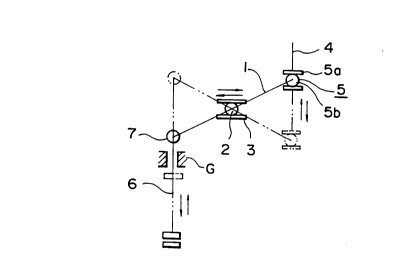
Referring to Figs. 3 to 6, reference numeral 1
denotes a lever member; 2, a fulcrum member for pivo-
tally supporting the lever member 1, 3, a fulcrum guide
member for freely movable supporting the fulcrum member
2; 4, a force point regulator pivotally and movably con-
nected to a force point, or one end of the lever member
1 through a connecting member 5; and 6, an action point
regulator pivotally connected to an action point, or the
203~005
other end of the lever member 1 through a connecting
member 7. Note that the connecting member 5 for con-
necting the lever member 1 and the force point regulator
4 is preferably constituted by a known cam follower type
member having a roller 5b which is in rolling contact
between a pair of guide plates 5a.
In each of the embodiments shown in Figs. 3 to 6,
the force point regulator 4 is linearly and vertically
moved, and the guide member 3 linearly, horizontally,
and rollingly supports the roller type fulcrum member 2
axially supported on the lever member 1.
Each of the embodiments shown in Figs. 3 and 4
employs an internal fulcrum obtained by locating the
fulcrum member 2 between the force point 5 and the
action point 7 of the lever member 1. In the embodiment
shown in Fig. 3, the action point regulator 6 can be
vertically and linearly moved, as indicated by a locus
in Fig. 7. That is, when the force point regulator 4
is vertically driven, the lever member 1 is pivoted
about the fulcrum member 2. At this time, the fulcrum
member 2 of the lever member 1 is horizontally moved
by a distance X along the guide member 3 upon pivotal
movement of the lever member 1, so that the action point
regulator 6 is linearly and vertically moved. In the
embodiment shown in Fig. 4, the action point regulator 6
is obliquely and linearly moved. In this embodiment, a
connecting member 7 disposed at the action point of the
2 0 3 4 0 ~ ~
-- 8 --
lever member 1 is subjected to elliptical motion.
The locus of the action point of the lever appara-
tus having an internal fulcrum can be linear, as shown
in Fig. 7, or elliptical, as shown in Fig. 8 or 9. A
movement distance X of the freely movable fulcrum in
Fig. g is smaller than that in Fig. 8.
In the embodiment shown in Fig. 5, the fulcrum
member 2 and the force point regulator 4 are located
at the two ends of the lever member 1, respectively,
and the action point regulator 6 is located at the
intermediate portion of the lever member 1, thus
constituting an external fulcrum configuration. In
this case, a stroke on the action point side is smaller
than that on the force point side, and a force is
increased.
In the embodiment shown in Fig. 6, the fulcrum
member 2 and the action point regulator 6 are arranged
at the two ends of the lever member 1, and the force
point regulator 4 is arranged at the intermediate
portion of the lever member 1. In this case, the stroke
on the action point side is larger than that on the
force point side, and a force is small.
In the embodiment shown in Fig. 6, the locus of the
action point regulator 6 is linear, as shown in Fig. 10,
the force point regulator 4 has a locus of a parabola,
and the fulcrum 2 has a locus of reciprocal motion. A
locus of the action point is elliptical in Figs. 11 and
2034û05
g
12.
In each of these embodiments described above, since
the fulcrum member 2 is freely moved in accordance
with motion of the force point regulator 4 and motion of
the action point regulator 6 upon pivotal movement of
the lever member 1, degrees of freedom of motion of the
force point regulator 4 and that of the action point
regulator 6 are large. The connecting member 5 of the
force point regulator 4 is moved to an optimal position
by a sum of kinetic functions of the action point regu-
lator 6 and the fulcrum member 2. For this reason,
while a motion range of the action point regulator 6 is
widened, a driving force from the force point regulator
4 can be effectively transmitted to the action point
regulator 6 through the lever member 1.
Motion of the fulcrum member 2, motion of the force
point regulator 4, and motion of the action point regu-
lator 6 can be any combination of vertical linear
motion, horizontal linear motion, oblique linear motion,
vertical circular motion, horizontal circular motion,
oblique circular motion, and the like, as needed.
The freely movable fulcrum type lever apparatuses
having the above arrangements can be widely used in
machine tools (e.g., a press apparatus), industrial
machines, and movable parts of various other structures.
An embodiment of a press apparatus which employs
the lever apparatus of the present invention will be
20340~
- 10 -
described with reference to Figs. 13 to 21.
The press apparatus of this embodiment is used to
connect a wire and a compression bonding terminal by
compression bonding.
A structure of the press apparatus will be
described with reference to Figs. 13 and 14.
A main body 22 is mounted on a base 21, and an
electric motor 23 is arranged in the main body 22.
A rotating shaft 24 is supported by a bearing 25a in
the main body 22, and a gear 26 is mounted on the
rotating shaft 24 to receive a rotational force from the
electric motor 23. An eccentric shaft 27 is mounted at
one end of the rotating shaft 24 at an eccentric posi-
tion. A guide member 28 is mounted outside one end of
the main body 22 along the vertical direction. The
eccentric shaft 27 mounted on the rotating shaft 24 is
rotatably inserted in a lift member 29 vertically
movably mounted on the guide member 28. A ram 31 is
inserted inside a holder 30 arranged in the lift member
29. The ram 31 can be vertically moved along a rail 29b
formed on the lift member 29. An adjusting screw 51
mounted in an upper end portion 2sa of the lift member
29 is threadably engaged with the upper end portion of
the ram 31 to regulate the lower position of the ram 31.
A vertically movable cam 32 having a bobbin-like shape
is mounted in a lower portion of the ram 31 and is sup-
ported upward by a nut 33 threadably engaged with
20340~
.
11
a threaded portion 31a formed at the lower end portion
A f the ram 31. The ram 31 is ~r~o~ urged against the
upper side of the cam 32 by a compression coil spring
34. In the driving mechanism having the above arrange-
ment, upon driving of the electric motor 23, the
rotating shaft 24 is rotated through the gear 26, and
the eccentric shaft 27 is eccentrically rotated about
the rotating shaft 24. Upon eccentric rotation of the
eccentric shaft 27, the lift member 29 is vertically
moved along the guide member 28. The ram 31 and the cam
32 are vertically moved together with the lift member
29. The lift member 29 and the ram 31 function as the
force point regulator.
A lever member 35 is disposed at a position near
the ram 31 on the base 21 in a direction perpendicular
to the rotating shaft 24. As shown in Figs. 15 and 16,
a fulcrum shaft 39 is mounted at an intermediate portion
of the lever member 35 in a direction perpendicular to
the longitudinal direction of the lever member 35.
Fulcrum rollers 38 are rotatably arranged at the two
ends of the fulcrum shaft 39. Guide members 40 are
mounted on the base 21 at positions respectively
corresponding to both sides of the lever member 35.
The fulcrum rollers 38 of the lever member 35 are
rotatably and movably inserted into guide grooves 41
respectively formed in guide members 40 along the
horizontal direction. The lever member 35 is pivoted
2034005
about the fulcrum shaft 39 in a vertical plane and can
be freely moved along the guide grooves 41 through the
rollers 38. Horizontal shafts 37 are mounted in the
arms of a Y-shaped portion 35a formed at a one-end
portion of the lever member 35. Rollers 36 are rot-
atably mounted on the shafts 37, respectively. The
Y-shaped portion 35a of the lever member 35 sandwiches
both sides of the cam 32 of the ram 31, so that the
rollers 36 are rotatably and movably fitted in the cam
32.
A pair of heads 42 and 43 are disposed at positions
near the lever member 35 on the base 21. As shown in
Figs. 17 and 18, the heads 42 and 43 resemble a wrench
head. The heads 42 and 43 are pivotally mounted through
pivot shafts 45 and 46 to a common connecting member 44
located at the intermediate portions of the heads 42 and
43 and can be opened/closed. The heads 42 and 43 have
projections 42a and recesses 43a which are adapted to
engage with each other. The heads 42 and 43 are mounted
on a head table 47 on the base 21 such that the proximal
portions of the heads 42 and 43 are directed toward the
lever member 35, one head 43 is horizontally located as
a lower head, and the lower head 43 is fixed by bolts
48. The proximal end portion of the upper head 42 is
rotatably connected to the other end of the lever member
35 through a connecting shaft 49. Note that the proxi-
mal end portion of the lower head 43 is connected to the
20340~5
head table 47 through a connecting shaft 50.
An operation of the press apparatus having the
above structure will be described with reference to
Fig. 18 to Fig. ~-.
As shown in Fig. 20, Fig. 2, and Fig. 17, the upper
head 42 is open to set a wire S and a compression
bonding terminal (not shown) in the recess 43a of the
lower head 43, as shown in Fig. 17. In this case, the
eccentric shaft 27 in the driving mechanism is moved to
the top dead point to move the ram 31 upward. As shown
Iq
in Fig. ~, the rotating shaft 24 is rotated to move the
27 to the bottom dead point to move the ram 31 downward.
Upon downward movement of the ram 31, this motion is
transmitted to the lever member 35 through the cam 32
and the rollers 36. The lever member 35 is pivoted
clockwise about the fulcrum shaft 39. At the same time,
the fulcrum roller 38 is moved toward the head along the
guide grooves 41 of the guide members 40, and the lever
member 35 is thus freely moved accordingly. In this
case, by a combination of the cam 32 and the rollers 36,
the lever member 35 can be moved relative to the ram 31.
Upon pivotal and movable operations of the lever member
35, the upper head 42 is pivoted counterclockwise about
the pivot shaft 45. The projection 42a compresses
the wire S and the compression bonding terminal (now
shown) which are set in the recess 43a of the head
43, thereby compression-bonding the wire S to the
2034~0~
- 14 -
compression-bonding terminal. Note that the connecting
member 44 is also operated about the pivot shaft 46.
Upon completion of compression bonding, the rotat-
ing shaft 24 is rotated to move the eccentric shaft 27
to the top dead point. In this case, the operations are
opposite to those described above.
A compression bonding force is adjusted by adjust-
ing the position of the ram 31 by the adjusting screw
51. Degrees of openings between the heads 42 and 43 are
adjusted by adjusting the nut 33, as shown in Figs. 20
and 21, to change the length A or B of a spring 34.
Since the lever member 35 is supported by the ful-
crum 39 to perform a combination of pivotal and movable
operations, the head 42 can be efficiently operated for
compression bonding upon motion of the ram 31. The
motion of the lever member 35 can absorb unnecessary
motion of each part, i.e., backlash. The motion of the
ram 31 can be transmitted to the head 42 without any
waste, and a slow operation can be performed. The force
of the ram 31 can be effectively transmitted while sys-
tematic operations are performed.
In this embodiment, the ram 31 is connected to the
lever member 35 by a combination of the cam 32 and the
rollers 36. This arrangement has an advantage in that a
large mechanical strength can be obtained, in unneces-
sary motion can be absorbed, and motion transmission
can be performed without any loss.
203400~
- 15 -
The present invention is not limited to the above
embodiments, but can be changed and modified in a vari-
ety of applications.
In the freely movable fulcrum type lever apparatus
of the present invention, as described above, the lever
member is supported by a movable fulcrum, and the range
of motion of the force point regulator connected to the
lever member and the range of motion of the action point
regulator can be largely increased.
In the press apparatus of the present invention,
the lever member supported by the fulcrum is used to
systematically and properly perform a press operation by
causing the heads to perform motion suitable for the
press operation.
In the lever apparatus used in the press apparatus
shown in Fig. 16, the fulcrum rollers 38 mounted on the
support shaft 39 are in rolling contact with the guide
grooves 41, thereby constituting the freely movable
fulcrum. In a structure shown in Figs. 22A and 22B,
without using the fulcrum roller, a lever member 65
is pivotally supported by a fulcrum shaft 64 inserted
into holes formed in sliders 62a and 62b inserted into
guide grooves 63a and 63b formed in guide members 61a
and 61b of a freely movable fulcrum regulator. One end
of the lever member 65 is connected to a slider 67
through a shaft 66 inserted into holes of the slider 67
in the same manner as the support point shaft 64.
203~005
The slider 67 is slidably inserted between guide members
68a and 68b of a force point regulator. The other end
of the lever member 65 is connected to an action point
member 70 through a shaft 69. The action point member
70 is inserted into a guide member 71 of the action
point regulator fixed on the ground and is regulated to
perform linear motion. In this case, the outer surfaces
of the sliders 62a, 62b, and 67 are finished with high
precision, and the inner surfaces of the guide grooves
63a, 63b, 68a, and 68b are smoothed to reduce frictional
forces, thus posing little practical problems. In
particular, as shown in Fig. 23A, since a force trans-
mitted to the shaft 66 is always transmitted
perpendicularly, no torsion stress in the conventional
arrangement shown in Fig. lA is generated.
However, in order to smooth movements of the sli-
ders 62a, 62b, and 67, a plurality of ball bearings 72
can be inserted between the guide grooves 63a and 63b
and the sliders 62a and 62b, as shown in Figs. 23A and
23B. Note that rollers may be used in place of ball
bearings.
Figs. 24 and 25 show other embodiments of freely
movable fulcrum structures. In the embodiment of
Fig. 24, a fulcrum shaft 80 is mounted on a support mem-
ber 81, and a lever member 82 is pivotally supported onthis fulcrum shaft 80. The support member 81 is fitted
in a bearing groove formed on a bed 83 fixed on the
203~005
ground G. The support member 81 is movable through ball
bearings 84 inserted between the support member 81 and
the bearing groove in a direction indicated by an arrow.
One end of the lever member 82 is connected to a driving
shaft 87 through a cam follower type connecting member
having a roller 86 inserted between guide plates 85 of
the force point regulator. The other end of the lever
member 82 is connected to a link rod 90 supported on an
action point regulator 89 through a shaft 88. In the
movable fulcrum formed as described above, fulcrum shaft
80 is not moved but the support member 81 is freely
moved on the bearings 84.
In the embodiment of Fig. 25, a lever member 82
pivotally supported on a fulcrum shaft 80 is movably
supported in a direction of straight rails 84a on a
support member 81 placed on a bed 83 fixed on the ground
G through the rails 84a, thereby constituting a freely
movable fulcrum.
Fig. 26 shows a press apparatus having a lever
apparatus having the fulcrum with the structure shown
in Fig. 24. This press apparatus has substantially the
same arrangement as that of the press apparatus shown
in Figs. 13 and 14, but is different therefrom in an
arrangement of a movable fulcrum of the lever apparatus.
In the press apparatus shown in Fig. 13, the lever
member 35 is pivotally supported by the fulcrum shaft 39
on the rollers 38 which are in rolling contact with the
203400~
- 18 -
fulcrum grooves 41 formed in the fulcrum member 40. In
the press apparatus of Fig. 26, however, the structure
of the fulcrum of the lever apparatus is identical to
that shown in Fig. 24. A lever member 90 is pivotally
supported by a fulcrum shaft 92 on a support member 91.
The support member 91 is freely movable held on a main
body 94 through ball bearings 93.
One end of the lever member 90 is connected to a
vertical driving shaft 96 through a cam follower struc-
ture 95 serving as a force point. The lower end of thevertical driving shaft 96 is connected to an eccentric
shaft 98 through a crank mechanism 97. Upon rotation of
the eccentric shaft 98, the vertical driving shaft 96 is
vertically moved. One end of the eccentric shaft 98 is
connected to an electric motor 99 through a power
transmission mechanism 100 such as a gear unit and is
driven and rotated.
The other end of the lever member 90 is connected
to a lift member 102 through a shaft 101 serving as an
action point, and a head 103 mounted on the lift member
102 is vertically driven, as shown in Fig. 26. In this
embodiment, a rotational force of the electric motor 99
is transmitted to the lever apparatus through each link
mechanism. A flywheel and the like need not be used,
unlike in the conventional apparatus. The apparatus can
be made compact, and at the same time, a mechanical
power can be smoothly transmitted to the head 103
~ 203~0~
- 19 -
through the lever apparatus having the freely movable
fulcrum.
Fig. 27 is a circuit diagram for driving and
controlling the press apparatus shown in Fig. 26.
Referring to Fig. 27, one terminal of an AC power source
110 is connected to one terminal of a parallel circuit
of a timing switch 112 and a foot switch 113 through a
power switch 111. The other terminal of this parallel
circuit is connected to one terminal of a motor 99
through a slight movement setting switch 114. The power
switch 111 is connected to one terminal of the motor 99
through a slight movement switch 115. The motor 99 is
connected in parallel with a brake 116. The timing
switch 112 is used to stop the head 103 at an upper
position after the head 103 is moved downward and is
then moved upward upon completion of a predetermined
work. The timing switch 112 is, e.g., a limit switch
mounted at the upper limit position of the lift member
102. The switch 112 is kept off only at this upper
limit position. The slight movement setting switch 114
is normally ON. The slight movement setting switch 114
is turned off to slightly move the head 103. As a
result, the motor 99 can be freely driven to slightly
move the head regardless of the ON/OFF states of the
switches 112 and 113. A counter 117 is arranged to
count the number of driving cycles of the motor 99,
i.e., the number of press operation cycles of the head
~ 2034~05
- 20 -
103, as needed.
Fig. 28 shows an application in which the pre-
sent invention is applied to a surface grinder having
a stroke adjustable fulcrum point as a movable fulcrum.
Referrlng to Fig. 28, a head 120 is supported
through bearings 122 so that the head 120 can be
smoothly moved along a support member 121 on the
horizontal plane. A lower portion of the head 120 is
axially supported at one end of a lever member 124 by a
shaft 123 serving as an action point. The lever member
124 is connected to a fulcrum member 126 engaged with a
screw rod 125. The fulcrum member 126 is movably and
pivotally mounted on the ground G through a linear
bearing mechanism 127. The screw rod 125 is connected
to a rotating shaft of a motor 129 mounted on the lever
member 124 through a gear unit 128.
The other end of the lever member 124 is connected
to a linear bering mechanism 130 through a shaft 131
serving as a force point. The linear bearing mechanism
130 is connected to a servo motor 134 through a crank
shaft 132 and a crank mechanism 133.
In the above arrangement, a rotational force of the
servo motor 134 is converted into a linear motion through
the mechanisms 132 and 133, and the linear motion is
transmitted to the shaft 131 serving as a force point of
the lever member 124. Therefore, the lever member 124
is supported by the fulcrum member 126 and linear
~03~QO~
bearing mechanism 127 and is pivoted so that the bed 120
can be smoothly moved in the horizontal direction.
In this case, when the motor 129 is driven, the
screw rod 125 is rotated through the gear unit 128, and
the fulcrum shaft 126 is freely moved on the bearing 127
to change a distance between the shafts 123 and 131,
thereby changing a stroke of the bed 120.
Fig. 29 is a block diagram of an electrical control
system of surface grinder shown in Fig. 28. Referring
to Fig. 29, the servo motor 134 and the brake motor 129
are driven by outputs from a servo motor control output
circuit 141 and a movable fulcrum point variable brake
motor output circuit 142 which are controlled by a CPU
140. A speed of the servo motor 134 is detected by a
servo input encoder 143, and a detection signal is input
to the CPU 140. A rotation state of the brake motor 129
is detected by an encoder 144, and a detection signal is
input to the CPU 140.
The CPU 140 is connected to a ROM/RAM 145, programs
of the entire system are stored, and input data are also
stored. An output from a control console through a
keyboard interface 148 is output to the CPU 140 through
a bus line 146. Various types of data stored in the
RAM 145 are supplied from the CPU 140 to a CRT 150
through a display output interface 149 and are displayed
on the CRT 150.
Fig. 30 shows an embodiment in which the lever
203~0~
- 22 -
apparatus of the present invention is applied to a
building damping apparatus. A crank shaft 132 identical
to that of Fig. 28 is connected to a crank mechanism and
a servo motor tneither are shown) through a shaft sup-
port member 155. One end, i.e., a force point side, ofa lever member 157 is connected to one end of the crank
shaft 132 through a cam follower mechanism 156. A ful-
crum 158 of the cam follower mechanism is formed at the
central portion of the lever member 157. The other end
serving as an action point is connected to a damping
block 160 through a pin 159. The damping block 160 is
movably held on straight rails 161a and 161b. The
straight rails 161a and 161b are fixed at positions
having a maximum magnitude at the time of earthquake
occurrence, e.g., on a middle floor of a skyscraper.
An operation of the damping apparatus will be
described with reference to Fig. 31. When an earthquake
occurs to vibrate a building, vibrations are detected by
a vibration sensor 162, and magnitude and direction data
of the vibrations are supplied to the CPU 140. The CPU
140 sends a driving signal to a servo motor 134 through
a servo motor control circuit 141 in the same manner as
in Fig. 28 to drive a damping block 160 to move in an
opposite direction with an identical magnitude to cancel
the vibration of the building. A movement amount of the
damping block 166 is detected by an encoder 143 as rota-
tional amount and direction of the servo motor 134.
~03~0~5
Earthquake vibrations generally occur several
cycles per second. It is easy to move the damping block
160 at this speed. In a conventional damping apparatus,
the damping block 160 is moved by using a feed screw,
and the response speed is low. In addition, since the
block 160 is extremely heavy, the mechanical strength
of the feed screw is not sufficient. As a result, a
sufficient damping effect cannot be obtained. However,
as in this embodiment, a good result can be obtained
by a combination of the lever apparatus having a freely
movable fulcrum and the straight rails 161a and
161b.
Fig. 32 shows an application in which the lever
apparatus of the present invention is used in a driving
mechanism for a diaphragm pump. A lever member 171
which receives a pivotal force from a cam follower type
force point regulator 170 in a direction of an arrow is
pivoted about a fulcrum 172. A diaphragm 175 of the
diaphragm pump is vertically driven through an action
point regulator 174 connected to an action point 173.
Fig. 33 shows an application in which the lever
apparatus of the present invention is applied to
an automobile shock absorber. Referring to Fig. 33,
an action point of a lever member 183 is pivotally
supported by a link 182 for connecting an automobile
shock absorber 180 and an automobile wheel 181. The
lever member 183 is connected to a force point regulator
~ 0 3 ~
- 24 -
185 through a freely movable fulcrum 184. The force
point regulator 185 is connected to a servo motor 187
through a crank shaft 186 in the same manner as in the
damping apparatus shown in Fig. 30. The fulcrum 184
and the servo motor 187 are fixed on an automobile body
G.
The principle of the automobile shock absorber
is substantially the same as that of damping for a
building. Motor driving with the arrangement shown in
Fig. 31 is performed to effectively absorb automobile
vibrations.
In each of the embodiments described above, only
one lever apparatus of the present invention is used.
However, two or more lever apparatuses may be combined
to constitute a force transmission system, as shown in
Fig. 34. A first lever apparatus 190 has a lever member
192 supported by a fulcrum 191, and a force acting on a
first force point 193 is transmitted from a first action
point 194 to a second force point regulator 196 through
a link 195. The force transmitted to the second force
point regulator 196 is transmitted to a second action
point regulator 199 through a fulcrum 198 of a second
lever apparatus 197. All support portions indicated by
G are represented by the ground.
Two or more fulcrums are used to constitute a chain
system of the lever apparatuses to freely set a force
transmission direction.
20~0~
- 25 -
Fig. 35 shows an application of an X, Y table using
the pivot lever apparatus of the present invention. In
this arrangement, a table 210 can be moved along rails
211a and 211b along the X direction. The arrangement
and operation in the Y direction can be made in the same
manner as in the X direction, and are omitted. The
table 210 is axially supported at one end of a lever
member 213 through a shaft operated as an action point.
A roller 217 in a driving guide member 216 serving as a
force point of a ball screw rotation feed mechanism 215
is mounted at the other end of the lever member 213
through a fulcrum 214. The guide member 216 is
threadably engaged with a ball screw 219 driven by a
motor 218.
Fig. 36 shows a motion locus of each portion in
Fig. 35. When the ball screw 219 is fed, e.g., every
10 ~m, an action point 212, i.e., the table 210, is
moved every 2 ~m. The roller 217 serving as a force
point is moved within the guide member 216 and has an
arcuated locus. The fulcrum 214 is freely moved by w
in response to feeding of the ball screw 219 by 80 ~m.
The action point 212 is moved by 16 ~m (= 80/5).
When the X, Y table is arranged as described above,
the table 210 is driven with very high precision. The
X, Y table can be used in a semiconductor wafer exposure
apparatus.