Note: Descriptions are shown in the official language in which they were submitted.
-a
The invention relates to a protective circuit for the protection of a system
to be
protected from overvoltage and over-current, in particular for
telecommunication
installations.
As disclosed in VDE 0845, part 1, October 1987, protective circuits in which
each cable conductor is protected by a surge arrester to earth are known in
the art. In
order to protect the surge arrester against the damages due to permanent
current loads,
it is frequently provided with a heat-sensitive protection device which short-
circuits the
surge arrester in the event of excessive heating. Since the cable conductor
may be
damaged by the short-circuit current, a melt fuse is incorporated in series
with the surge
arrester, the melt fuse cutting the current conduction in case of high
current. A
disadvantage is that the fuses must be selected to stand the surge current
existing in
normal operating conditions, and for this purpose, the fuses have to be rather
voluminous.
German published application DE-OS 38 31 935 discloses a protective circuit,
comprising a fuse connected in the cable conductor and a cross path between
the cable
conductor and an earth conductor connected after the fuse. The cross path
comprises a
surge arrester thermally coupled with a heat-sensitive protection device. An
excessive
thermal load on the surge arrester will lead to a response from the heat-
sensitive
protection device, disconnecting the cross path. With a permanent current
load, the fuse
will disconnect the current conduction. When the cross path is disconnected,
the system
side of the protective circuit is no longer protected from short-term over-
voltages, and until
the fuse disconnects, the system side will be supplied with the over-current.
The fuse has
to be, therefore, resistant against surge current, which requires a large
volume.
Furthermore, after a response from the heat-sensitive protection device and
subsequent
disconnection of the fuse, if any, the cable conductor of the system side of
the protective
circuit will no longer be at a defined potential, so that destruction of
sensitive components
may occur.
An object of the invention is, therefore, to provide a protective circuit for
the
protection against overvoltage and over-current, which protects the surge
arrester from
excessive thermal loads, and which disconnects current conduction in case of
excessive
current loads in a way that is safe for the system side, and will diminish the
risk of fire.
Accordingly, an aspect of the present invention provides a protective circuit
for
protecting a system to be protected against overvoltage and over current, the
protection
circuit having a line side and a system side connected to the system to be
protected, the
2
protective circuit comprising: a line conductor electrically connecting the
line side to the
system side; an earth conductor electrically connected to ground; a fuse
series connected
in the line conductor; a surge arrester normally connected between the line
conductor on
the line side of the fuse and the earth conductor; a normally open short-
circuit cross path
connected between the line conductor on the system side of the fuse and the
earth
conductor; a heat-sensitive protection device responsive to a rising
temperature of the
surge arrester to disconnect the surge arrester from the earth conductor and
to
simultaneously close the short-circuit cross path, whereby, upon triggering
the heat-
sensitive protection device the system side of the protective circuit is
connected to ground,
and current flows from the line side of the protective circuit through the
fuse and to ground
via the short-circuit cross path and the earth conductor.
A further aspect of the present invention provides a protective circuit for
protecting a system to be protected against overvoltage and over current, the
protection
circuit having a line side and a system side connected to the system to be
protected, the
protective circuit comprising: a line conductor electrically connecting the
line side to the
system side; an earth conductor electrically connected to ground; a fuse
series connected
in the line conductor; a normally closed bypass switch connected in parallel
with the fuse;
a surge arrester normally connected between the line conductor on the system
side of the
fuse and the earth conductor; a normally open short-circuit cross path
connected between
the line conductor on the system side of the fuse and the earth conductor; a
heat-sensitive
protection device responsive to a rising temperature of the surge arrester to
simultaneously
disconnect the surge arrester from the earth conductor, open the bypass switch
and close
the short-circuit cross path, whereby, upon triggering the heat-sensitive
protection device
the system side of the protective circuit is connected to ground, and current
flows from the
line side of the protective circuit through the fuse and to ground via the
short-circuit cross
path and the earth conductor.
When over-voltages exist for an excessive period of time, the surge arrester
will heat up, and will operate, thus, the heat-sensitive protection device.
The latter
disconnects the cross path of the surge arrester, and closes, simultaneously,
the short-
circuit cross path on the system side of the fuse, so that the current line
can then be
disconnected by the fuse. Due to the short-circuit cross path, the input of
the system side
is then at a defined potential, namely earth.
s
~~~~.7,~2
3
During an inadmissibly high current loading, which may occur, for example,
due to an overvoltage on the current line, the current line may be
disconnected without the
surge arrester being tripped. Since, in this case, the heat-sensitive
protection device does
not respond, the short-circuit cross path is not closed, so that here, too,
the fire hazard
caused by the excessive current in the short-circuit line is reduced.
In one embodiment, the branch of the cross path of the surge arrester is
connected on the line side of the fuse, so that the fuse is not traversed by
current surges
and may therefore be selected small. UVhen the heat-sensitive protection
device is
operated, the short-circuit cross path after the fuse is closed, so that the
fuse will open the
line conductor in response to a high current. Since tripping of the heat-
sensitive protection
device causes opening of the cross path of the surge arrester, subsequent
operations of
the surge an-ester are prevented until reset of the device.
In another embodiment, the cross path of the surge arrester and the short-
circuit cross path are connected on the system side of the fuse which is short-
circuited
during normal operation and is connected in the circuit when the cross path of
the surge
arrester is disconnected. Here, the surge current load is also diverted from
the fuse. The
latter is disposed on the line side of the branch of the surge arrester and of
the open short-
circuit cross path. Connected in parallel across the fuse is a short-circuit
switch so that
in normal operating condition, the fuse is traversed by a small part of the
current only.
Tripping of the heat-sensitive protection device will lead to opening of the
short-circuit
switch bridging the fuse, and closing of the short-circuit cross path between
current line
and earth line, so that the fuse is activated.
The protective circuit may be symmetrically doubled for protecting two current
lines of a double conductor, wherein, upon operation of the heat-sensitive
protection
device, both surge arresters are disconnected from the earth line by a common
change-
over switch, and both short-circuit cross paths are closed. Herein, the
protective circuit is
mounted into a double conductor as it is commonly done in the
telecommunication sector.
Between each of the two current lines and the common earth line, the
protective function
is achieved such that, upon tripping of only one heat-sensitive protection
device, the
common safety function is activated, both surge arresters are disconnected
from the earth
line, and both short-circuit cross paths are closed. Instead of two separate
surge arresters,
a three-pole surge arrester can also be employed.
:a
4
Furthermore, in these embodiments, the protective circuit may be further
provided with a fine protection circuit, so that according to VDE 0845, part
1, October
1987, a stage-type protection by coarse and fine protection is obtained. The
fine
protection circuit may comprise a positive temperature coefficient (PTC)
resistor and a
varistor, thermally closely coupled. Such components are known in the art from
the
German published application DE-OS 32 31 066. The fine protection circuit
permits the
protection to quick transient events and to over-voltages and over-currents,
where the
coarse protection does not respond. The voltage-dependent resistor (varistor)
limits the
voltage to the desired maximum level, and operates very quickly, having a
response time
on the order of nanoseconds. The temperature-dependent (PTC) resistor, which
is series
connected in the line, serves for decoupling between the voltage limits in the
coarse
protection from those in the fine protection. Further, the PTC resistor serves
for limiting
currents which are larger than the common and admissible operating currents by
the
heating-up of the PTC resistor due to the current flow. Finally, the PTC
resistor serves for
overload protection limiting the voltage on the fine protection (varistor).
This is obtained
by the increase of its resistance due, on one hand, by self-heating of the PTC
resistor by
the current flow, and on the other hand, by the heating-up of the PTC resistor
induced by
the thermal coupling of the PTC resistor with the varistor.
A measuring and disconnecting block is connected in other preferred
embodiments on the system side of the stage protection for effecting partial
testing of the
parameters of the protective circuit and of the current line with incorporated
protective
circuit. In telecommunication installations, it is particularly advantageous
to adapt such
protective circuits as protective plugs.
In the following, the invention is described in more detail, based on several
embodiments represented in the drawings wherein:
Figure 1 illustrates the circuit diagram of the first embodiment of the
protective
circuit provided with a fuse arranged on the system side of the surge
arrester, for
application in double conductors, in operating condition;
Figure 2 illustrates the protective circuit according to Figure 1 in tripped
condition;
Figure 3 illustrates the circuit diagram of a second embodiment of the
protective circuit with a bridged fuse arranged on the line side of the surge
arrester;
5
Figure 4 illustrates the block diagram of an embodiment of the protective
circuit
including a stage protection and a measuring and disconnecting block;
Figure 5 illustrates the circuit diagram of the stage protection;
Figure 5a, which appears with Figures 12-14, illustrates the circuit diagram
of
another embodiment of the protective circuit;
Figure 6 shows a longitudinal section through the protective plug;
Figure 7 shows a top view of the circuit board of the protective plug;
Figure 8 shows a cross section through the protective plug along line A-B in
Figure 6;
Figure 9 shows a cross section through the protective plug along fine C-D in
Figure 6;
Figure 10 shows the bottom view of the protective plug where the circuit board
is removed;
Figure 11 shows a top view of the protective plug; Figure 12 illustrates a
side
view of a connector bank of the telecommunication installation with five
inserted protective
plugs, with a mounted earth rail and a set-up signal bracket, operated by the
signalling
lugs of the protective plugs,
Figure 13 illustrates a front view of the connector bank with inserted
protective
plugs and signal bracket in not folded-down condition; and
Figure 14 illustrates a front view according to Figure 13 with folded-down
signal bracket.
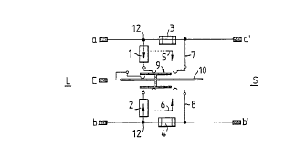
Referring now to Figure 1, a protective circuit is shown arranged between the
terminals a-b and a'-b' of line side L and system side S, respectively. A
common earth
conductor E is provided for absorbing over-current generated by over-voltages
referenced
to the earth potential. The protective plug comprises two surge arresters 1,
2, connected
between the terminals a and E, and b and E, respectively, and fuses 3, 4
connected in the
line conductors between the terminals a, a' and b, b', on the system side of
the nodes 12
connecting the surge arresters 1, 2. The surge arresters 1, 2 are thermally
controlled by
heat-sensitive protection devices 5, 6. Figure 1 shows the protective circuit
in normal
operating condition, i.e. the surge arresters 1, 2 contact a change-over
switch 9, which is
connected over a base 10 with the earth line E. The short-circuit cross paths
7, 8 are
opened, and are, in normal operating condition not connected with the change-
over switch
9. An overvoltage which lasts long enough to trip the surge arrester 1 or 2,
is conducted
6
to earth E via the surge arresters. Therefore, the resulting over-current,
will not transverse
the fuses 3, 4.
In Figure 2, the protective circuit of Figure 1 is represented in tripped
condition.
An excessive thermal load at one of the two surge arresters 1, 2, i.e. an
excessive current
load, will operate the corresponding heat-sensitive protective device 5 or 6,
respectively,
and cause the operation of the common change-over switch 9. This is shown here
by the
displacement thereof toward the right. Thereby, the short-circuit cross paths
7, 8 are
connected to the earth line, and these cross-paths are closed. The cross paths
of the
surge arresters 1, 2 are disconnected. The fuses 3, 4 are activated now, and
they can
interrupt the line conductors between the terminals a - a' and b - b'. The
terminals a', b'
on the system side S are now at a defined potential, namely the earth
potential, so that
protection of personnel and of sensitive electronic circuitry on the system
side S is
obtained. The fire hazard caused by the protective circuit is also
significantly reduced.
Figure 3 shows another embodiment of the protective circuit with a modified
arrangement of the fuses 3', 4'. A fuse 3' is arranged in the line conductor
between the
terminals a, a' on the line side of the node for the cross path of the surge
arrester 1. The
short-circuit cross path 7, arranged on the system side of this node is opened
in normal
operating condition, whereas the cross path of the surge arrester 1 contacts
the change-
over switch 9, and thus the earth line E. The fuse 3' is short-circuited by a
closed switch
11 connected across it. The heat-sensitive protection device 5 simultaneously
operates
the change-over switch 9 and the switch 11, such that tripping of the heat-
sensitive
protection device 5 will cause opening of the cross path of the surge arrester
1 and closing
of the short-circuit cross path 7. Simultaneously, the switch 11 across fuse
3' is opened,
so that the fuse 3' is activated over the short-circuit cross path 7.
The separation of the protective circuit into a coarse protection 20 and a
fine
protection 21 in the form of a stage-type protection is shown in the
protective circuit
according to Figure 4. This stage-type protection is followed by a measuring
and
disconnecting block 22.
Figure 5 shows an embodiment of the stage-type protection with measuring
and disconnecting block 22. Between each line conductor connecting the
terminals a - a',
and b - b' and the earth conductor E, the coarse protection 20, the subsequent
fine
protection 21 and the subsequent measuring and disconnecting blocks 22 are
connected.
The coarse protection 20 comprises the cross paths with the surge arresters 1,
2, the
r
7
subsequent fuses 3, 4 provided in the line conductors, the short-circuit cross
paths 7, 8,
the heat-sensitive protection devices 5, 6 and the common change-over switch
9. The
subsequent fine protection 21 comprises the PTC resistors 30, 31 each
connected in the
respective line conductor, followed by the varistors 32, 33 connected in
between the
respective line conductor and the earth conductor E. The earth potential is
established as
another measuring terminal 35, for allowing potential measurements between the
measuring and disconnecting positions 34 and the measuring position 35 for the
earth
potential.
Figure 5a, which appears with Figures 12-14, shows another embodiment of
the protective circuit with a signalling device. The protective device
comprises a three-pole
surge arrester 1' connected between the line conductor terminals a, and b, the
central
electrode 13 being connected over a slide contact 14 with the change-over
switch 9 (i.e
slider 45 in Figures 6, 8 and 10) and earth potential. The fuses 3, 4 are
provided in the
line conductors on the system side of the cross path of the three-pole surge
arrester 1'.
The heat-sensitive protection devices 5, 6 and the short-circuit cross paths
7, 8 are
provided as in the previous embodiments. The earth conductor E contacts the
change-
over switch 9 over a slide contact 15. The measuring and disconnecting
positions 34 are
also provided in the line conductors between the terminals a, a' and b, b'.
The change-over switch 9 is provided with a contact maker 16. The
connection line 17 of the contact maker 16 may be connected, along with other
protective
plugs 99 (shown in Figure 12), to an electronic signal transducer 18 connected
over a
resistor 19 to a line 24. Line 24 has a signal transducer 25, for a central
signal, and an
exchange battery 26. The protective circuit provides for a centralized
signalling, displaying
whether or not a protective plug 99 has been tripped in a protected field,
e.g. of a main
distribution frame of the communication installation. The free end of the
change-over
switch 9 serves, herein, as a signalling lug 56 (see Figure 12), which will
contact the
contact maker 16 with tripped protective plug 99. Thus the contact maker 16
has the earth
potential. If, thereby, the circuit is closed over the local signalling
transducer 18, then the
tripping condition of the protective plug 99 can be indicated at the main
distribution frame
or in a field, and, if applicable, also at a connector block, by a lamp, LED,
buzzer or by
another signalling device. Contact should not be permanent, but may have a
type of
trigger function. If applicable, power supply of the signalling device may be
obtained over
a DC/DC converter, since protective earth may accept a high potential. Over
interfaces
8
connected to counting mechanisms, heavily loaded current lines, (e.g. with
frequent
tripping) can be found out.
Figure 6 shows a central longitudinal section through a protective plug 99
arranged as a miniature plug provided with a stage-type protective circuit
with a measuring
and disconnecting position 22. The miniature plug is used particularly in the
telecommunication sector. An external housing 40, the lower section of which
is formed
of a circuit board 41, includes a three-pole surge arrester 42, the central
electrode of which
contacts a sheet-metal part 43. Such a three-pole surge arrester 42 comprises
a left-hand
and a right-hand external electrodes and a common central electrode 13, so
that two spark
gaps are formed between the external electrodes and the central electrode 13.
The sheet-
metal part 43 is conductively connected, over a solder position 44, with a
conductive
(metal) slider 45 at a lug 46 showing extending, the lug 46 being guided in a
guide slot 81
in the circuit board 41. The slider 45 rests with contact projections 47, 48
(one of which
is visible in Figure 6) on the circuit board 41, and is spring-loaded at its
side directed
toward the surge arrester 42, by means of a spring 88 mounted on a guide pin
49. The
spring 88 is supported, at its other end, on an internal housing wall 50,
forming, together
with an internal housing top wall 51 and the second (left-hand) transverse
wall 52 of the
housing in Figure 6, a cavity 107 for receiving the surge arrester 42, so that
it is
surrounded by the walls 50, 52 and the top wall 51. The slider 45 is
contacted, along its
top edge, by an earth plate 53 adapted as a resilient member. The latter is
located in a
hollow section 55 being formed by the internal top wall 51 and the external
top wall 29 of
the housing 40, the external top wall being open toward the external (second)
transverse
wall 52 of the housing 40 and serving for receiving an earth plug or an earth
rail 98 (see
Figure 12). For establishing a better contact, the earth plate 53 is provided
with a spring
tongue 54 arranged in the hollow section 55.
The slider 45, forming the change-over switch 9, comprises a signalling lug 56
disposed at the end opposite to the spring 88. With tripped safety operation
of the plug,
the signalling plug 56 passes through an opening 87 of the first (right-hand)
transverse wall
57 of the housing. Therein, another opening 58 is provided, said opening being
limited by
the circuit board 41. This opening 58 serves for receiving a not-shown
measuring and
disconnecting plug, and comprises spring tongues 59, 60 (see Figure 9)
contacting the
circuit board 41 in normal condition, i.e. when the measuring and
disconnecting plus is not
installed.
f y,
9
Figure 7 shows the circuit board 41 which is part of the housing 40 of the
protective plug 99. Board 41 has at its left-hand end, a contact tongue 61. On
the shown
face of the circuit board 41, contact areas 62, 64 are provided for contacting
the line-side
terminals a, b and which are followed by line side circuit tracks 63, 65. On
the opposed
side of the circuit board 41, similar contact areas for contacting the system-
side terminals
a', b' are provided. These are connected, via through-contacts 66, 68, with
the system
side circuit tracks 67, 69 extending in parallel to the line side circuit
tracks 63, 65. In the
circuit tracks 63, 65, there are provided narrow sections 70, 71 forming the
fuses 3, 4.
Each of the circuit tracks 63, 65, 67, 69 ends on the end of the circuit board
41 opposite to the contact tongue 61, in rectangular, elongate contact zones
72, 73, 74
and 75. In each of the contact zones 72 and 75, two bores 76, 77 and 78, 79,
respectively, are provided. Such bores 76 to 79 serve for receiving vertically
mounted
contact plates 96, 97. Approximately in the middle of the circuit board, there
is provided
a recess 80 for receiving the sheet-metal part 43 (illustrated in Figure 6).
Further, a guide
slot 81 is provided, which extends from the recess 80 toward the end of the
circuit board
41 opposite to the contact tongue 61, and which serves for receiving the lug
46 of the
slider 45. The support positions 82, 83 mark the positions where the contact
projections
47, 48 (see Figure 10) of the slider 45 are placed in operating condition.
These are
arranged in the area where the narrow sections 70, 71 of the circuit tracks
63, 65 serving
as fuses 3, 4 are located. Therefore, in operating condition, the contact
projections 47, 48
of the slider 45 will not contact circuit tracks 63, 65. The contact positions
84, 85 provided
on the contact zones 72, 75 mark the position of the contact projections 47,
48 in the
tripped condition.
The safety function of the protective circuit is tripped by the melting of the
solder position 44, connecting the slider 45 with the contact plate 43 of the
surge arrester
42. The contact plate 43 provides for a close terminal contact. Melting of the
solder
position 44 permits movement of the slider 45 due to the pre-tensioned spring
88. The
slider moves away from the surge arrester 42, and disconnects the contact
between the
surge arrester 42 and the earth plate 53. The contact projections 47, 48 move
from their
non-contacting support positions 82, 83 to the contact positions 84, 85.
Therefore, a direct
short-circuit between the earth plate 53 and the circuit tracks 63, 65 is
established, on the
system side of the narrow sections 70, 71 forming the fuses 3, 4. The
signalling lug 56
10
advances through the opening 87 in the transverse wall 57 of the housing 40.
Its function
will be described in detail in the following.
Figure 8 shows a section through the protective plug 99 along the sectional
plane A-B in Figure 6. The protective plug 99 is surrounded by the housing 40
enclosed
by the circuit board 41. The slider 45 comprises two L-shaped metal slider
portions 90,
91, which are combined in the form of a T-piece, such that the long legs 90' ,
91' forming
the crosspiece of the T-piece, are tensioned relative to each other, and form
an acute-
angled V-shaped spring. At the respective ends of the short legs 90", 91 ",
forming the
flange of the T-piece, there are the contact projections 47, 48 resting on the
circuit board
41. The slider 45, forming the change-over switch 9, contacts at its top edge
the earth
plate 53 by means of the elastic force in the earth plate 53.
At each side of the long legs 90', 91' of the slider portions 90, 91, a disc-
shaped varistors 32, 33 separating contact plates 94, 95, PTC resistors 30,
31, and
external contact plates 96, 97 are provided. The contact projections 92, 93
press on the
varistors 32, 33 due to the elastic force produced by the long legs 90', 91'
of the slider 45,
and thus contact them electrically. The contact projections 92, 93 are
disposed on the
inner side of the long legs 90', 91' of the L-shaped slider portions 90, 91.
The PTC
resistors 30, 31 have a rectangular shape, and the varistors 32, 33 have a
cylindrical
shape, their heights being smaller than their diameters. Each varistor 32, 33
is electrically
connected at the base surface with a respective PTC resistor by means of a
separating
contact plate 94, 95. Due to the large contact areas, the thermal contact is
also very good.
Figure 9 shows a cross-section through the protective plug 99 along line C-D
in Figure 6. The housing 40 with the circuit board 41 are illustrated. To the
internal side
of the housing 40 walls, contact plates 96, 97 extending vertically, are
provided. The
contact plate 96 is soldered vertically on the circuit board 41 in bores 76,
77 and the
contact plate 97 is soldered vertically into the bores 78, 79. Inwardly,
hollow sections 100,
101, adapted to receive the left-hand and the right-hand PTC resistors 30, 31
are provided.
Then, the separating contact plates 94, 95 electrically connect the PTC
resistors 30, 31
with the varistors 32, 33. The receiving spaces 102, 103 are arranged for
receiving the
varistors 32, 33. Centrally, the signalling lug 56 of the slider 45 is shown.
Between the
receiving spaces 102, 103 for the varistors 32, 33 and the circuit board 41,
the spring
tongues 59, 60 of the measuring and disconnecting contacts are provided. The
hollow
11
spaces 100, 101 (for receiving the PTC resistors 30, 31 ), the receiving
spaces 102, 103
(for receiving the varistors 32, 33) spaces for the separating contact plates
94, 95 and for
the spring contact tongues 59, 60 are formed in a corresponding moulded body
104.
Furthermore, another opening 105, for passing the signalling lug 56 of the
slider 45 is
provided at the front end of the protective plug body 104.
In Figure 10, a bottom view of the protective plug 99 with removed circuit
board 41 is shown. Each contact spring tongue 59, 60 serving for contacting
the contact
zones 73, 74 of the circuit board is rigidly connected with one of the
separating contact
plates 94, 95. Thereby, the connections between the line-side terminals a, b
and the
system-side terminals a', b' are established over the PTC resistors 30, 31, in
the absence
of a measuring and disconnecting plug. Figure 10 shows, further, the hollow
spaces 100,
101 and the receiving spaces 102, 103 for receiving the PTC resistors 30, 31
and of the
varistors 32, 33 respectively. Centrally, the slider 45 with the contact
projections 92, 93
is represented and its flange side formed of the short legs 90", 91 ". At the
ends thereof,
the contact projections 47, 48 are attached at the bottom side. The guide lug
49 of the
compression spring 88 projects through the internal housing wall 50. On the
other side of
the housing wall 50, there is the receiving space 107 for receiving the three-
pole surge
arrester 42. Figure 11 shows a top view of the protective plug 99. There are
shown
the contact plates 96, 97, the separating contact plates 94, 95 the hollow
spaces 100, 101
and the receiving spaces 102, 103 for receiving the PTC resistors 30, 31 and
the varistors
32, 33 respectively. The earth plate 53 partially projects over the hollow and
receiving
spaces 100 to 103, and over the receiving space 107 of the surge arrester 42
with the
spring tongue 54. The latter serves for contacting the earth rail 98, (see
Figure 12), as will
be described in the following.
Instead of the varistors 32, 33, voltage-limiting semiconductor elements may
be employed. The varistors, the diodes and the other components can be used
for
modifications of the basic models in the production (modular design).
Figure 12 shows a connector block 89 for a the telecommunication installation
with five mounted protective plugs 99 and one earth rail 98. At both sides of
the connector
block 89, a U-shaped signal bracket 36 is supported over pivot bearings 37.
The legs 38
of the signal bracket 36 are slightly longer than the height of the protective
plugs 99 when
mounted on the connector block 89. The connection piece 39 of the signal
bracket 36 is,
therefore, in the active zone of the tripped signalling lugs 56 of the
protective plugs 99.
$'
i
12
On the internal side of the long connection piece 39 of the signal bracket 36,
there is
provided an electrically conductive contact strip 106, connected over the
connection line
17 (shown in Figure 5a) to the central signalling system.
A protective plug 99 with projecting signalling lug 56 is shown in Figure 12.
This means that due to an interference with subsequent heating, the solder
position 44 has
melted and the signalling lug 56 of the slider 45 was pushed out from the
housing 40,
under the action of the spring 88. The visible signalling lug 56 touches now
the contact
strip 106, and closes the signal circuit, according to the circuit diagram
shown in Figure 5a
to the earth conductor E.
Figure 13 shows the front view of the connector block 89 with signal bracket
36 arranged thereupon in operating condition. Figure 14 shows the front view
according
to Figure 13 with folded-down signal bracket 36, allowing replacement of the
protective
plugs 99 and to allow an easy access to the measuring and disconnecting
contact.
Folding-down of the signal bracket 36 is necessary, since otherwise, the
protective plugs
99 could not be pulled out. Folding-down of the signal bracket 36 is also
possible in the
opposite sense from the one shown in Figure 14, if further connector blocks 89
provided
on the one side of the connector block 89 with mounted protective plug 99
would obstruct
folding-down.
An addition signalling may also be implemented to operate by closing the
signal circuit of Figure 5a, even when the signal bracket 36 is folded down as
in Figure 14.
This would avoid an inadmissible switching-off of the signalling by a folding-
down signal
bracket 36. In this way even during folding-down of the signal bracket 36, a
signal is given
by a non-shown contact. The signal bracket 36 itself may incorporate a
signalling element,
e.g. an LED, a lamp or the like, in order to facilitate correction of a fault.