Note: Descriptions are shown in the official language in which they were submitted.
2Q~3 ~ 2~
Bridge comprising a deck and at least two towers, and process for the
construction thereof.
The present invention relates to a bridge, in particular a bride of a very
large span, of the type comprising a deck, at least two towers and a certain
number of cables or stays connecting the tops of the towers to the deck in
order to support the latter.
Hitherto, bridges of a very large span (greater than 1000 m) have been
constructed with suspended decks. The most simple form of these known
structures comprises one or more main suspension cables, tensioned between
two towers, above which they are deflected in order to be anchored at the end
of the side spans in powerful anchor blocks. The deck carrying the traffic
1 0 (road, railway, fluid conduits, etc.) is suspended from the suspension cables by
suspenders which are generally approximately vertical and regularly spaced
out along the length of the structure.
With the materials currently available (framework steel and steel for
suspension cables), the maximum clear span of such structures is greater than
3000 m; however, the cost of the suspension cables and of the anchor blocks
increases extremely quickly with the span. Furthermore, the vertical
deformations of the deck and the variations in the longitudinal inclination of
the latter under the passage of the moving loads (lorries or trains) soon
become critical. In order to limit the bending and rotations to acceptable
values, structures must be built which are highly surbased and in which the
height of the towers above the deck is 1/10 to 1/9 of the clear span, in other
words the distance between two successive towers. This limitation further
increases the weight and the cost of the suspension cables and of their anchor
blocks.
2 5 In order to overcome these disadvantages, for approximately the last
thirty years engineers have turned to cable-stayed bridges. The deck is
2 2 ~; ? ~
suspended from multiple stays distributed uniformly over its length,
generally in an approximately symmetrical manner on either side of each
tower. The vertical loads of the deck are divided into a tension sustained by
the stays and a compression sustained by the deck. The tensions of the stays
are generally selected in such a way that the reaction force imposed on the
tower is vertical, with the result that the compressions in the deck are
balanced on either side of the tower. The height of the towers can be selected
to be much larger than for suspension bridges: 1/5 to 1/4.5 of the clear span,
with the result that the cost of the stays is reduced whilst increasing the
rigidity of the structure. Lastly, the anchor blocks are no longer necessary,
which represents a considerable saving in the overall cost of the structure.
On the other hand, the deck is now subjected to substantially
compressive forces which must be taken into account in the calculations. For
a deck sustaining a total load (permanent loads + moving loads) w per unit
length, and assuming that all the stays are anchored to the top of the tower,
the axial compressive force N in the deck varies parabolically from zero (at
the crown of the central span of at the end of the side span) to a maximum
value at right angles to the tower equal to N = wa2/2h, a being the distance
from the tower to the crown of the central span or to the end of the side span,
and h being the height of the tower above the deck. It can be seen that a
doubling of the span, all other things being equal, results in a quadrupling of
the compressive load. (For the sake of simplification, the weight of the stays
has been ignored in this expression). With the properties of the current
materials, the limit span of a cable-stayed bridge lies between 1000 and 1500 m;2 5 it is determined by the exhaustion of the compressive strength of the deck
under the effect of the axial force (plus, of course, the various thermal effects
and the bending moments created by the passage of the moving loads).
In its field of application, the cable-stayed bridge is more rigid than a
suspension bridge and substantially more economical. This intrinsic
~r
~ '
3 2Q53~
advantage is confirmed by the fact that in the last twenty years, 10 times more
cable-stayed bridges have been constructed than suspension bridges in the
range of clear spans from 200 to 800 m.
In order to widen the field of application of cable-stayed bridges beyond
their current limit span, the idea was mooted of combining the two systems
of staying and suspension. In its most simple form, this combination consists
in constructiong, from each tower, two traditional cable-stayed decks over a
first length on either side of each tower. The central part of the main gap,
over a second length on either side of the crown, is then suspended from a
cable which is itself anchored in external blocks by vertical suspenders. Such
a solution is described, in particular, in "Connaissance des ouvrages d'art No
3-4,1988-89: Darius Amir-Mazaheri - A 3000-metre bridge - an advance in the
study thereof", pages 68-71.
More complex, so-called "net and lattice" solutions have also been
proposed, see in particular "Cable support Bridges, Concept and Design", by
Niels GIMSING, published by John Wiley and Sons, pages 176-183. In the
structure proposed by this author, it is possible to distinguish deck parts
supported in the traditional manner by stays anchored at each of their ends at
points situated on either side of towers these stays being deflected at the top of
2 0 the corresponding tower; these deck parts being followed, towards the middle
of the central span, by cable-stayed parts in which the stays, at their other end,
are anchored in an anchor block situated beyond the side span. The bridge
furthermore comprises a short central part which is supported, via vertical or
inclined suspenders, by a suspension cable which joins the same anchor
2 5 blocks to the ends of the bridge. There may also be a partial overlapping
between this "suspended" part and the adjacent cable-stayed part. The
horizontal forces resulting from the action of the weight of the deck on the
stays and the suspenders are balanced by a compressive force in the cable-
stayed parts of the deck, a tensile force in the central part of the deck, and a
~ O '~ 3 4
tensile force in the suspension cable. It is possible, for example, to calculatethe lengths of the parts of the bridge in such a way that these three forces areequal.
These mixed solutions have as yet not got beyond the designer stage
and no structure of this type has been made. This is probably because such
designs attempt to combine in one and the same structure two fundamentally
different techniques: stays on the one hand and suspension cables and
suspenders on the other hand. Not only are the structural behaviours
different, but the materials and the technology for the construction are also
very different.
It has also been proposed, Swiss Patent 447, 247, to support the central
part of the span exclusively by stays which are anchored, on the one hand, in
anchor blocks situated beyond the deck and are deflected in the upper part of
the towers, and, on the other hand, towards the ends of the central part. This
central part is then subjected, between the stays which are deflected by one
tower and those which are deflected by the other, to a considerable tensile
stress, which limits the dimensions which it is possible to give this central
part.
The object of the present invention is to eliminate such difficulties and
2 0 thus to bring multiple-cable-stayed bridges into the range of span previously
reserved for suspension bridges.
The invention consequently provides a bridge comprising a deck and at
least two towers, the part of the deck which extends on either side of each
tower being supported by stays which are anchored on the deck and tensioned
2 5 between their anchorage points on the deck and points situated at the top of
the tower or distributed over the height of the latter, the longitudinal
compressions in this part of the deck which result from the tensioning of the
stays being approximately balanced on either side of the tower, the deck
furthermore comprising a central part situated approximately half-way
5 ?~0~3~
between two successive towers and which is supported exclusively from these
two towers, by stays which are anchored, on the one hand, in this central part
of the deck and, on the other hand, on one or other of two anchor blocks
beyond the deck, and are each deflected at the top of the tower situated
between said central part and said anchor block, which has as its feature that
the central zone of the deck is subjected to an axial prestress, calculated in
order to compensate at least partially for the tensile stress to which the central
part is subjected under the effect of the said stays anchored on the anchor
blocks.
There is no departure from the invention if the stays have a
discontinuity at the level of a tower and consist, for example, of a part
anchored on the deck and on the tower and of a part anchored on the tower
and on the anchor block. The part of the tower which connects these two
anchorage points ensures the continuity of the transmission of the forces and
1 5 can thus be considered as part of the stay.
The prestress is advantageously calculated in order to balance
substantially the maximum tensile load half-way between the towers.
The zone subjected to the prestress corresponds, in a simple manner, to
the central part mentioned above. In particular, a slightly longer prestressed
2 0 zone would make it possible to reduce further the compressive stress at right
angles to the towers, where it is greatest, but it would give rise to an
imbalance which would have to be compensated for, for example by exerting
a tension on the deck from the anchor blocks.
It is also possible to reduce the effect of the compressive stresses by
providing, in a known manner, that the stressed cross-section of the deck
changes along the length of the structure in order to adapt to the variation in
the forces which it sustains.
The practical value of the design of the invention presupposes that the
problems of construction of the structure can be overcome.
6 2~ 3~2~
The invention consequently also provides a process for the
construction of a bridge as defined above, and which comprises the following
- constructing the anchor blocks and, simultaneously or independently,
erecting the towers and constructing the parts of the deck which are
supported by stays anchored on these deck parts on either side of the
tower,
- putting in place, between each deck part already constructed and the
adjacent anchor block, jacks or removable members capable of
transmitting a horizontal reaction force,
- constructing the central part of the deck with the aid of stays anchored
in the anchor block, working from the deck parts already constructed
and compensating for the imbalance in the horizontal forces with the
aid of the jacks or the removable members,
- keying the centre of the deck,
- applying the prestress to the central part of the deck.
During the construction, the part of the deck which is adjacent to the
towers is subjected to compressive forces which are greater than those which
it is intended to sustain in service, when the bridge is not loaded. This
2 0 temporary overload should be compared with the additional overload which
will result from the use of the bridge. If necessary, its effects could be
compensated for by providing for the stressed cross-section of the deck to
change along the length of the structure in order to adapt to the variation in
the maximum forces which the said deck must sustain during construction.
It is also possible to construct the deck of the central part in several
stages, the keying of the centre of the deck taking place before the deck has its
final form and weight.
According to an advantageous modus operandi, during the
construction of the central part, the symmetrical stays of the family of stays
._ ,.
2 Q ~ 3 i~ ~ iJ
intended to support this central part are balanced in pairs by connecting these
stays together using ties fixed in proximity to their anchorage point on the
deck.
Furthermore, it is advantageous to apply this prestress to the central
part of the deck in a gradual manner by simultaneously relaxing the force of
the jacks or removable members.
The invention will now be explained in more detail with the aid of
illustrative embodiments illustrated in the drawings and in which:
Figure 1 is a diagrammatic view in elevation of a suspension bridge.
Figure 2 is a diagrammatic view in elevation of a conventional cable-
stayed bridge.
Figure 3 is a diagram of the axial stresses of the deck of the bridge in
Figure 2.
Figure 4 is a diagrammatic view in elevation of a mixed cable-
1 5 stayed/suspension bridge.
Figure 5 is a detailed view of the bridge in Figure 4.
Figure 6 is a diagrammatic view in elevation of a bridge according to
the invention.
Figure 7 is a diagram showing the distribution of the stresses in the
2 0 central part and the corresponding stays.
Figure 8 is a diagram similar to that in Figure 7 and showing the
distribution of the stresses on the part adjacent to a tower.
Figure 9 is a diagram of the stresses of the deck of the bridge in Figure 6.
Figure 10 is a diagram of the stresses in the deck of a preferred
alternative embodiment.
Figures llA, llB, llC are diagrams showing stages in the construction
of a bridge according to the invention.
Figure 12 is a diagram of the stresses in the deck, in the situation in
Figure llC.
.,~
8 ~0`~3~29
Figure 13 is a detail of Figure llC.
Figures 14A and 14B are diagrams illustrating a preferred alternative
embodiment of the mode of construction.
Figure 15 is a detailed view of Figure 14B.
Figure 1 shows a suspension bridge in which one or more main
suspension cables 1 pass over the top of two towers 2 and are anchored in
anchor blocks 3. The deck 4 is suspended from the cables by suspenders 5
which are here shown to be vertical and regularly spaced apart. The weight
W of the elements of the deck is compensated for by the tensioning of the
suspenders 5, and lastly the total weight of the deck is compensated for by a
tension Q exerted by the cables on the anchor blocks.
Although the example envisages only two towers, it is, of course,
possible to provide a larger number of them. This is, moreover, applicable in
the entire description below.
1 5 Figure 2 shows a cable-stayed bridge of the conventional type, in which
the two towers 6 each carry half the length of the deck 4 via stays 7, the ends of
which are anchored on either side of the tower in a substantially symmetrical
manner. The deck is therefore split up by the towers and the crown of the
span into four substantially equal lengths a. The vertical load W of the deck
2 0 generates an axial compression N of the deck between two symmetrical stays.
As shown in Figure 3, this compressive force is maximum at right angles to
the towers 6, and it is zero at the end of the side span and at the crown 8 of the
central span. As mentioned above, this maximum force is equal to N = W
a2/2h.
Figure 4 shows a bridge of the "mixed" type, such as that which has
been proposed. On either side of the tower 6, a deck part of length al is
supported by stays 7, in the same manner as in the case of Figure 2.
furthermore, a suspension cable 1 similar to the cable 1 in Figure 1 passes
over the top of the towers 6, is retained by anchor blocks 9 placed on either
~-
.~
..~ .:~li
~ O . .' f~
side of the bridge, and supports, via vertical suspenders 10, a central part of
the deck of total length a2. The total span of the bridge between two towers is
equal to L = 2(al + a2).
Figure 5 shows the gradual transition between the purely cable-stayed
part of the deck and its purely suspended part. In addition to the suspenders
10, cables 11 are anchored to the deck, in the vicinity of the purely cable-stayed
part. These cables 11, after being passed over the top of the towers 6, are
anchored on the anchor block 9.
The middle part 12 of the deck is supported solely by suspenders 10.
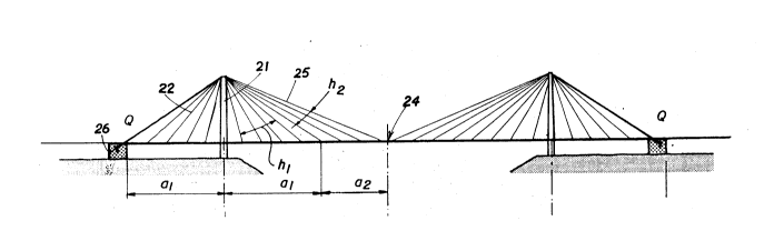
Figures 6 to 9 relate to a bridge according to the invention. In this
bridge, the length of the deck is divided into three parts: two parts 20, cable-stayed in the conventional manner, each situated on either side of a tower 21
and each supported by a series of cables 22 anchored symmetrically with
respect to the tower and deflected at the top of the latter, and a central part 23
15 situated on either side of the crown 24 of the central span and supported by
stays 25 which, after having been deflected at the top of the tower 21, are
anchored in an anchor block 26.
It will be noted that, instead of the described arrangement of the stays
25, which is termed "fan-shaped", it is possible to provide, without departing
20 from the invention, an arrangement of the "harp-shaped" type in which the
stays reach the tower at separate points distributed over the height of this
tower. Neither is there any departure from the invention if the stays do not
extend continuously from an anchorage point on the deck but consist of two
sections which are each anchored on the tower and on the deck.
2 5 Figure 7 shows that, from one anchor block 26 to the other, there is aseries of tensioned elements consisting of the stays 25 of a first half, of the
central part, the deck of the central part 23 itself, and the stays situated on the
other side of this central part.
2~3~
1 0
Figure 8 shows, on the other hand, that, in the conventional cable-
stayed part, the load is balanced by the tension of the stays 22 and the
compression of the deck.
As shown in Figure 9, the stays 25 therefore do not produce any
additional compression in the deck on its portion adjacent to each tower.
However, the equilibrium in the loads between the stays and the deck in the
central part of the latter induces a series of axial tensile forces which
accumulate and give rise to a total axial force N2 at the crown of the central
span. Ultimately, the axial force N in the deck of the central span, created by
the horizontal component of the forces of the stays and which, in a
conventional cable-stayed bridge, would have just been a compressive force,
can be broken down according to the arrangements of the invention, into a
compressive force Nl in the part adjacent to the tower and a tensile force N2
in the central part. Assuming that the loads W are constant along the length
of the deck and ignoring the influence of the weight of the stays, it can easilybe found that, if al = 0.7 a is selected, i.e. a2 = 0.3 a, then Nl = N2 = N/2. It is
thus possible, with the same properties of materials, to increase the distance
of the central span in the rate of: 1/07 = 1.4, if it is assumed that the acceptable
compressive and tensile loads are identical.
In fact, it is possible to go much further by employing a second
arrangement of the invention. In the deck, the tensile forces T2 balancing the
horizontal component of the tensions, Tl of two symmetrical stays in the
central part 23 (Figure 7) can be compensated for by a prestressing force withinthe deck (irrespective of the material of which it is composed - steel or
2 5 concrete), preferably calculated in such a way that, when the deck sustains its
permanent loads and its moving loads, the axial force at the crown of the
central span is zero.
The result then is that, when the deck sustains only its permanent
loads, it is subjected, in the central span, to a compressive force Nl equal to
1 1
the prestress less the tensile stress produced at this moment by the stays 25,
and hence equal to the additional tensile force which results from the
moving loads.
In a road bridge of large span, greater than 1000 m for example, the
permanent loads G are three times greater than the moving loads S. As a
result the prestressing force is equal to 4Nl. Assuming that the maximum
compressive load at the crown Nl can be equal to the maximum compressive
load near ------- the towers N2, this gives the diagrammatic layout in Figure
10 in which the parabolic curve 30 has as its equation N = tG + S) a2/2h,
which is the equation which corresponds to a conventional cable-stayed
bridge. It can be seen that N = 5N2 at the most, which means that the term a2
is five times greater than what it would have been in a conventional cable-
stayed bridge. The span is therefore multiplied by ~5 = 2.25 approximately and
can hence attain values comparable to those of large suspension bridges.
The practical value of the new design proposed according to the
invention assumes, however, that all the problems of the construction of the
structure can be overcome. The foundations, towers and anchor blocks being
made beforehand (Figure 11A) the deck is constructed on either side of each
tower in an approximately symmetrical manner, employing the
2 0 corresponding stays 22 at each stage. When this stage of the work is finished,
the side spans are completed (Figure 11B) and adjusting jacks 31 (Figure 13)
capable of transmitting a horizontal reaction force R will be arranged in the
joint separating the end of the deck and the corresponding anchor block on
which it rests.
The construction of the deck of the central span can then continue
towards the crown. The stays of the second family are put in place and
anchored at the rear in the anchor block. The equilibrium of the system is
effected by the generation of the reaction force R which reaches its maximum
value when the deck is constructed as far as the crown. At this stage, the
.
.
,..~
1 2 ~ ~ ~ 3 ~ 2 ~
diagram of the axial forces in the deck is that of Figure 12. The structure in
this stage sustains only the dead weight of the deck, to the exclusion of the
loads resulting from the equipment (roadway wearing-surface, railings, etc.).
This dead weight generally represents half the total loads G + S mentioned
above. The axial force N1 borne by the deck at right angles to the tower is thusequal to N/2 (N having the meaning stated with respect to Figure 10). If full
use is made of the possibilities explained above (which is not necessarily the
optimum overall solution) for the dividing up of the deck between the two
parts a1 and a2 supported by the two families of stays, it can be seen that the
axial force in the deck during construction (N1 = 0.5N) is 2.5 times greater
than in the structure in service (N1 = 0.2N).
Three arrangements can be taken either separately or jointly in order to
deal with this situation, if the temporary stresses in the materials exceed
acceptable values:
a) changing the stressed cross-section of the deck, in particular near
the towers, which will make it possible to increase the length a1 to the
detriment of the length a2, whilst at the same time permitting the generation
of higher temporary forces in the deck;
b) constructing the deck of the central part in several stages in order
2 0 to reduce its weight before keying; for example, if the deck is composed of a
metal framework supporting a concrete slab, this slab will be put in place only
after the metal framework has been keyed;
c) reducing the value of the temporary reaction force R and,
therefore, that of the axial force in the deck by balancing the symmetrical stays
2 5 of the central family in pairs using ties.
This latter solution is illustrated in Figures 14A, 14B and 15.
Figure 14A shows a stage of the construction slightly after that in
Figure 11B. The conventionally cable-stayed part of the deck is complete and
~; '
,
1 3 ~ ^ 3 ;~ ~ ~
a small length of the central part has been built, on either side of middle of
the structure.
Figures 14B and 15 show that, in order to put in place an additional
length 32 of deck, the ends of the corresponding stays 25 have been join ed by
a tie 33. The additional lengths 32 will be made integral with the assembly
formed by the two stays 25 and the tie 33, which acts like the suspension cable
of a suspension bridge, in other words it does not create any new axial
compressive stress in the deck, or at least such as stress is considerably
reduced.
Whatever the method adopted, the structure is completed by the
keying of the central span at the crown and the application of the final
prestress of the deck. In order to prevent excessively high compressive forces
being exerted on the deck, the tensioning of the prestressing units at the
centre of the main span and the controlled relaxing of the jacks at the two
ends are carried out simultaneously. Once these operations are over, the deck
is free from the contact with the anchor blocks by removing the jacks 31, and
has its final static form.
. -
,, ~