Note: Descriptions are shown in the official language in which they were submitted.
X054006
Specification
The invention relates to an automatic food dispenser
for dispensing hot instant meals, the apparatus including a
housing having a front that is provided with operating
elements and a refrigeration chamber for storing a supply of
refrigerated packaged instant meals. At least one oven,
preferably a microwave oven, is disposed underneath the
refrigeration chamber and includes a cooking chamber for
accommodating a refrigerated instant meal, an oven door
provided with an opening mechanism and a movable cooking
surface which is mechanically coupled with the oven door. An
electromechanical removal device is provided at the underside
of the refrigeration chamber to remove an individual instant
meal from the refrigeration chamber and move it, with the
oven door open, onto the cooking surface. By way of a
discharge chamber accessible to the operator, the hot instant
meal is discharged to the operator.
Such an automatic dispenser, particularly for dispensing
hot pizza and other Italian dishes is disclosed in DE-A1-
3,738,708 which originates from the same applicant.
In the prior art apparatus, one or a plurality of
refrigerated food portions are removed from the storage
container by means of an electromechanical flap mechanism.
- 9 -
254006
Due to its own gravity, the food portion then slides over a
sloped surface onto a deflection flap which is lowered by
means of an electromechanical system when the oven door is
opened so that the food disposed thereon slides over a
further sloped surface into the interior of the oven. When
the heating process is completed, the oven door is opened
again and simultaneously the food heating surface which is
coupled by way of a mechanism is raised in such a manner that
the heated food portion is brought to the discharge chamber
over a further sloped sliding surface.
The removal and supply of food portions by means of the
electromechanical flap-and-slide system has not found
acceptance. It has been found that gravity alone is not
sufficient to ensure problem-free transport of the food
portions within the automatic dispenser. In particular, the
discharge of the heated food solely over sloped sliding
surfaces has been found to be fraught with problems since, on
the one hand, the hot food portions tend to stick to the food
heating surface and, on the other hand, there exists the
danger that the sensitive sliding material might be damaged
due to an excessive sliding speed which is difficult to
control.
The prior art apparatus has the further drawback that
only a quite specific product, for example pizza, for only
- l0 -
?U54~~06
one particular taste can be dispensed. However, the user of
a modern automatic dispenser expects to make a selection from
various products.
It is thus an object of the present invention to create
an automatic food dispenser for dispensing hot instant meals
where the dispenser has an improved mechanism for the removal
and transport of refrigerated and hot instant meals and which
offers a selection between various dishes.
The solution of this problem is based on an automatic
food dispenser of the above-described type. According to the
invention, the solution resides in that a drum-type storage
container that is rotatable about its vertical rotation axis
is provided within the refrigeration chamber and includes a
plurality of tubular magazines arranged on a circle each
accommodating a stack of refrigerated instant meals; the oven
includes a horizontally extendable push frame which has a
push front forming the oven door; a cooking tray having a
horizontal cooking surface is mounted on the push frame so as
to be raised and lowered in such a manner that, when the push
frame is extended, the cooking tray is moved upward from a
lowered cooking position within the cooking chamber into a
loading position outside of the cooking chamber; and, if the
push frame is pulled out fully, the cooking tray is moved
further upward into a discharge position within the discharge
- 11 -
chamber. Additionally, a movable closing member for the
refrigeration chamber is provided below the tubular magazines
and above the cooking tray when the latter is in the loading
position and finally the discharge chamber is disposed behind
a discharge opening in the front of the housing.
In the plurality of tubular magazines of the drum-type
storage container, different instant meals can be stored in
refrigerated or possibly even frozen state. By means of the
operating elements provided in the front of the housing, the
operator is able to select a certain tubular magazine which
is then turned into a predetermined position above the
stationary closing member of the refrigeration chamber. At
the same time, the oven disposed underneath the refrigeration
chamber opens by extending its push frame together with the
push front constituting the oven door. The cooking tray
disposed on the push frame then moves upward in synchronism
with the push frame into a loading position. No later than
when the cooking tray has reached its loading position
outside of the cooking chamber does the closing member of the
refrigeration chamber open and the product removed from the
selected tubular magazine travels onto the horizontal cooking
surface of the cooking tray. Upon closing of the oven door,
the cooking tray moves automatically back again into its
lowered cooking position within the cooking chamber. At the
- 12 -
2~5400~
end of the heating process, the oven door again moves out,
with the cooking tray again being moved upward automatically.
This time, however, the push frame moves out a little further
so that the cooking tray is moved correspondingly farther
upward into a discharge position within the discharge
chamber. Through the discharge opening provided in the front
of the housing, behind which the discharge chamber is
disposed, the operator is able to remove the desired hot
instant meal directly from the cooking tray.
The configuration of the oven door according to the
invention as a horizontally extendable push frame with push
front and the arrangement of a cooking tray that is automati-
cally raised on the push frame when the oven door is opened
constitutes a simple and reliably operating transporting
mechanism for the refrigerated instant meal into the cooking
chamber and for the discharge of the hot instant meal.
Together with the rotatable drum-type storage container which
permits the operator to make a selection from various dishes,
the invention provides a structurally simple, reliably
operating automatic food dispenser that satisfies the wishes
of the operator for the provision of hot instant meals.
In a first embodiment, the removal device includes, as a
closing member for the refrigeration chamber, a pivotal
closing flap disposed below the circular path of the tubular
- 13 -
2i~~400
magazines and above the cooking tray when the latter is in
the loading position. With the closing flap open, the
desired product slides out of the selected tubular magazine
onto the cooking tray.
The automatic food dispenser may include two identical,
juxtaposed ovens, with the closing flap then being disposed
in the middle between the two ovens and being pivotal to both
sides about its center axis. In this case each oven has its
own associated discharge chamber and discharge opening.
Thus, two operators can be supplied simultaneously with
different instant meals. Microwave ovens are particularly
suitable since they also thaw frozen foods very quickly and
heat them to consumption temperature.
In this embodiment of the automatic food dispenser, the
tubular magazines are provided with a support bottom for the
associated stack of instant meals, an ejection slot penetrat-
ing the support bottom in the circumferential direction and a
lateral ejection opening for the ejection of the respective
lowermost instant meal. A movable ejector is disposed in
the region of the closing flap to engage, when in the
ejection position, in the ejection slot of one of the tubular
magazines. The removal of the respective lowermost instant
meal from a tubular magazine is effected by rotation of the
drum-type storage container, while the ejector is in the
- 14 -
2054006
ejection position. Due to the relative movement between the
passing tubular magazine and the stationary ejector, the
ejector pushes the instant meal to be separated laterally
through the ejection opening in the tubular magazine in the
direction of the - then still closed - closing flap.
The ejector may be fastened, for example, to a pivot bar
that is mounted so as to pivotally move above the closing
flap and may slidingly rest on the upper face of the closing
flap in such a manner that, if the closing flap is opened,
the pivot bar is automatically moved upward from its rest
position into the ejection position. Instead of such a
passive ejection mechanism whose movement is coupled with the
pivotal movement of the closing flap, it is also possible,
however, to provide an independently activated ejector.
In a second embodiment of the automatic food dispenser
according to the invention, the removal device includes, as
its closing member, a sliding door provided in the bottom of
the refrigeration chamber and disposed below the tubular
magazines and above the cooking tray when the latter is in
the loading position. This horizontally movable sliding door
opens whenever an instant meal is to be removed from the
previously selected tubular magazine and placed onto the
cooking tray.
- 15 -
2~54~06
If the bottom of the refrigeration chamber is provided
with such a sliding door, the tubular magazines advisably are
each equipped with a support bottom for the stack of instant
meals, a radially outwardly oriented ejection opening for the
ejection of the respective lowermost instant meal and a
recess disposed directly above the support bottom and
opposite the ejection opening. A movable discharge slide is
provided which, when the sliding door is open, engages in the
recess of one of the tubular magazines and pushes the lower-
most instant meal radially outwardly through its ejection
opening. The discharge slide may here be coupled with the
sliding door by way of a pull frame so that opening of the
sliding door causes the discharge slide to automatically
engage in the selected tubular magazine and push out the
lowermost instant meal which then drops down due to gravity
onto the cooking tray in the loading position.
In order to prevent the laterally discharged instant
meal from tipping over the front edge of the support bottom
of the tubular magazine, the front edge of the discharge
slide - as a modification of the invention - is provided with
a pivotally articulated pivot plate which, in its rest posi-
tion, rests on the bottom of the refrigeration chamber and
flips vertically downward only when the sliding door is
fully open. In this way it is ensured that the instant meals
- 16 -
2054006
which form a flat stack in the tubular magazine drop flat
onto the cooking tray while maintaining their position
parallel to the bottom of the refrigeration chamber.
The proposed automatic food dispenser is particularly
suitable for the dispensing of pizza which is customarily
round. Advisably, the tubular magazines to store the
refrigerated or frozen instant meals also have a round cross
section. However, the tubular magazines may also have a
rectangular, particularly a square, cross section so as to
accommodate, for example, frozen packages of Italian pasta
dishes.
As a mechanism for the automatic raising and lowering of
the cooking tray during extension of the oven door, a
structure has been found acceptable in which the push frame
of the oven supports two bearing blocks disposed on the
sides, a pivotal lever having a short lever arm and a long
lever arm is pivotally mounted in each one of these bearing
blocks, the cooking tray is suspended from the ends of the
long lever arms in a pendulum fashion and at least one short
lever arm cooperates with a stop in such a manner that during
extension of the push frame, the pivot lever pivots upward
beginning after a certain distance is traversed. This purely
mechanical construction has the advantage that it does not
require its own drive but couples the movement of the cooking
- 17 -
2054006
tray with the extension of the push frame. The entire
automatic food dispenser is thus able to operate with only
three drives, namely a drive for rotating the drum-type
storage container, a drive for opening the closing flap at
the refrigerated container and a drive for extending the oven
door.
In an advantageous modification of the invention, the
automatic food dispenser additionally includes at least one
cutlery magazine disposed within the housing to accommodate a
stack of packaged sets of disposable cutlery and an as-
sociated removal slot in the front of the housing. The user
of the automatic food dispenser thus receives the suitable
cutlery together with the desired hot meal. Advisably an
electrically actuated discharge slide is provided at the
cutlery magazine to move the lowermost set of disposable
cutlery out of the cutlery magazine in the direction of the
discharge slot.
Two embodiments of the invention will now be described
in greater detail with reference to the attached drawing
figures. It is shown in:
Figure 1, the frontal face of an automatic food
dispenser for the simultaneous
discharge of two hot instant meals;
- 18 -
204006
Figure 2, an elementary perspective view of the
automatic food dispenser of Figure 2;
Figure 3, a partially sectional front view of
the automatic food dispenser of
Figure 1 without housing;
Figure 4, a partially sectional view from the
side of the automatic food dispenser
of Figure 3;
Figures 5a to 5f, the removal of an instant meal from
the refrigeration chamber of the
automatic food dispenser;
Figure 6, a perspective exterior view of the
housing of an automatic food dis-
penser for the discharge of only a
single instant hot meal at a time;
Figure 7, an elementary perspective view of the
automatic food dispenser according to
Figure 6;
Figure 8, a partially sectional view from the
front of the automatic food dispenser
of Figure 7 without housing;
Figure 9, a partially sectional view from the
side of the automatic food dispenser
according to Figure 8:
- 19 -
2054006
Figures 10a, lOb, a partially sectional side view to an
enlarged scale of part of the
refrigeration chamber and the removal
device of the automatic food dis-
penser according to Figure 9 with the
sliding door closed and open,
respectively;
Figure 11, a perspective view of a tubular
magazine of the automatic food
dispenser of Figure 7;
Figure 12, a perspective illustration of the
removal device of the automatic food
dispenser according to Figures 9, l0a
and lOb.
The automatic food dispenser shown in Figure 1 as seen
by the operator includes a housing 1 that is closed on all
sides. In its front 2, operating elements are inserted,
namely two coin slots 3 and fields of selection keys 4.
Associated with each operating element is a discharge opening
5 and 5', respectively, for the desired instant meal and a
double removal slot 6 for the discharge of packaged cutlery
sets.
- 20 -
2054006
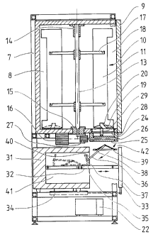
As can be seen in Figures 2, 3 and 4, housing 1 includes
a frame 7 in whose upper portion a refrigeration chamber 8 is
disposed. The interior of refrigeration chamber 8 is acces-
sible to authorized maintenance personnel through a door 9
that opens toward the front.
Refrigeration chamber 8 is composed of a drum-type
storage container 10 that includes six tubular magazines 11
which are arranged on a circle and each accommodate a stack
of frozen instant meals 12. Drum-type storage container 10
is mounted in an upper pivot bearing 14 and a lower pivot
bearing 15 so as to pivot about a vertical rotation axis 13.
By means of a drive motor 16 acting on rotation axis 13,
drum-type storage container 10 can be caused to rotate, thus
moving tubular magazines 11 on a circular path. The in-
dividual tubular magazines 11 are suspended from mounts 17
that are radially fastened to rotation axis 13 so that they
can be easily removed for maintenance purposes. The walls of
tubular magazines 11, which have a circular cross section,
are provided with radially outwardly oriented cutouts 18
through which the instant meals 12 can be inserted for
storage once the front 2 and the door 9 of refrigeration
chamber 8 are opened.
At their lower ends, tubular magazines 11 are provided
with a support bottom 19 on which rests the stack of instant
- 21 -
2054006
meals 12. Ejection slots 20, curved to correspond to the
circular path on which the tubular magazines 11 travel,
penetrate the support bottoms 19. Lateral ejection openings
21 serve to eject the respective lowermost instant meal 12.
A refrigeration unit 22 disposed in the lower portion of
frame 7 maintains the required low storage temperature within
refrigeration chamber 8.
A rectangular opening 23 is provided in the underside of
refrigeration chamber 8 to be followed downward by a removal
chute 24. A closing flap 25 closes removal chute 24 and thus
refrigeration chamber 8 toward the bottom in a cold-insulated
manner. Closing flap 25 can be pivoted to both sides about
its center axis 26. By means of an electrical servomotor 27,
closing flap 25 can be selectively pivoted clockwise or
counterclockwise.
Above closing flap 25, in the side walls of removal
chute 24, a pivot bar 28 is mounted so as to be pivotally
movable. Approximately in its center, pivot bar 28 is
provided with an ejector 29 which here is configured as a
rectangular plate. The lower edge of ejector 29 rests
slidingly on the upper side of closing flap 25. In order to
reduce friction, the lower end of ejector 29 is provided with
a small roller 30.
- 22 -
Two identical ovens 31 and 31' are arranged in parallel
next to one another in the lower portion of frame 7. The
heat is generated by way of electromagnetic microwaves. Each
oven 31 and 31', respectively, includes a horizontally
extendable push frame 32 equipped with a push front 33 which
constitutes the oven door. A lifting cylinder 34 serves as
the drive for push frame 32. On its right and on its left,
push frame 32 is provided with a laterally disposed bearing
block 35. A pivot lever 36 equipped with a short lever arm
37 and a long lever arm 38 is pivotally mounted in its as-
sociated bearing block 35. At the ends of the long lever
arms 38, a cooking tray 39, 39' is freely suspended in the
manner of a pendulum so that its planar cooking surface is
always horizontal. In the interior of oven 31, a stop 40 is
provided both on the right and on the left side and cooper-
ates with the corresponding short lever arm 37 (see Figure
4) .
If oven 31 is closed, that is, push frame 32 and push
front 33 are fully retracted, cooking tray 39 is in its
lowered cooking position within cooking chamber 41 as shown
in dashed lines in Figure 4. If now push frame 32 is
extended toward the front, the fixed stop 40 comes in
contact, after a certain length of travel, with the short
lever arm 37 that is moved along with the push frame. Upon
- 23 -
further extension of push frame 32, this leads to pivot lever
36 being pivoted and the cooking tray 39 suspended therefrom
being raised outwardly toward the top. In Figure 4, cooking
tray 39 is shown in solid lines in the loading position.
After an instant meal 12 taken from refrigeration chamber 8
has been placed on the cooking surface, push front 33 of oven
31 closes again, causing cooking tray 39 to return to its
lowered cooking position within cooking chamber 41 due to the
interaction between short lever arm 37 and stop 40 cor-
responding to the travel performed.
After an instant meal 12 has been heated within oven 31,
its push frame 32 again moves upward, causing cooking tray 39
to be automatically raised again. If push frame 32 is
extended forward somewhat beyond the position shown in Figure
4, the cooking tray also moves somewhat further upward in the
direction of the arrow until it reaches its discharge
position within a discharge chamber 42 slightly below closing
flap 25. In this discharge position (not shown), the
operator is able to reach through the respective discharge
opening 5 (see Figure 2) into the discharge chamber 42
immediately behind it and remove the hot instant meal
directly from the cooking surface 40 of the raised cooking
tray 39.
- 24 -
~~54006
Figure 2 also shows that cutlery magazines 43 which
each accommodate a stack of packaged sets of disposable
cutlery are disposed on the left and on the right in housing
1. These cutlery magazines 42 are provided with electrically
actuated discharge slides 44 by means of which the respective
lowermost set of disposable cutlery is pushed forward out of
the respective cutlery magazine 43 so that the operator can
grasp it through the associated removal slot 6 in front 2.
The separation and removal of a frozen instant meal 12
from refrigeration chamber 8 and its placement onto cooking
tray 39 will now be described with reference to Figures 5a to
5f.
In Figure 5a, closing flap 25 is in its horizontal rest
position in which it seals the removal chute 24 in a cold-
insulated manner toward the bottom. Ejector 29 and its
roller 30 lie loosely on the upper face of closing flap 25.
Pivot bar 28 carrying ejector 29 is also disposed in its
horizontal rest position. A tubular magazine 11 is disposed
vertically above opening 23 in the underside of refrigeration
chamber 8 and thus also directly above closing flap 25. The
lowermost frozen instant meal 12 rests on the slightly sloped
support bottom 19 of tubular magazine 11 and its side already
projects slightly out of ejection opening 21.
- 25 -
204006
The removal process is now initiated by clockwise
rotation of closing flap 25 about approximately 20 angular
degrees as shown in Figure 5b. This automatically also
pushes pivot bar 28 and ejector 29 upward in the direction
of tubular magazine 11.
In the next process step shown in Figure 5c, tubular
magazine 11 is moved by slowly rotating drum-type storage
container 10 on its predetermined circular path in the
direction of the arrow. This brings the upper portion of
ejector 29 in finger-like engagement with ejection slot 20 in
support bottom 19. Due to the relative movement between
tubular magazine 11 and stationary ejector 29, instant meal
12 begins to be pushed laterally out of ejection opening 21.
Once tubular magazine 11 has been moved far enough in the
direction of the arrow, the instant meal finally drops from
support bottom 19 onto the surface of closing flap 25.
Then (see Figure 5d) closing flap 25 returns to its
horizontal rest position. Due to the particular structural
configuration of removal chute 24 and the only limited
pivoting of closing flap 25 about approximately 20 degrees,
the removal of an individual instant meal 12 from tubular
magazine 11 could be accomplished without cold air from
refrigeration chamber 8 escaping toward the bottom.
- 26 -
~~~~~~1~1~i
The actual discharge of the selected instant meal 12
from refrigeration chamber 8 is now effected by further
pivoting of closing flap 25, with the rotation angle about
center axis 26 now being larger, however, and amounting to
about 30 degrees. As can be seen in Figure 5e, a slit thus
opens between the lower edge of removal chute 24 and the
upper face of the pivoted closing flap 25 through which the
instant meal 12 is able to slide obliquely downward.
Depending on the direction in which closing flap 25, which is
disposed in the middle between the two ovens 31 and 31', is
pivoted, the instant meal slides_toward the right (Figure 5e)
or toward the left (Figure 5f). Closing flap 25, which is
pivotal about its center axis 26 in the same manner in both
directions, thus constitutes a switch with which an in-
dividual instant meal 12 can be selectively supplied to the
cooking tray 39 of the left oven 31 or to the cooking tray
39' of the right oven 31' (see Figure 3).
At the end of the above-described removal and supply
cycle, the closing flap returns to its horizontal closing
position as shown in Figure 5a.
The control and coordination in time of drive motor 16
which causes drum-type storage container 10 to rotate, of
servomotor 27 which pivots closing flap 25, of lifting
cylinder 34 for opening oven 31 and 31', respectively, and
- 27 -
~~54~06
of discharge slides 44 at cutlery magazines 43 is effected by
means of an electronic control unit (not shown in the
drawings) which also includes a control for maintaining the
correct heating times.
Figure 6 shows the closed housing 101 of an alternative
embodiment of the automatic food dispenser which differs from
the above-described automatic dispenser primarily in that it
includes only a single oven and thus is able to discharge
only a single hot instant meal at any one time. Accordingly,
only a single coin slot 103 and one field with selection keys
104 are provided in front 102. There is also only a single
discharge opening 105 for the desired instant meal and next
to it a single discharge slot 106 for cutlery.
According to Figures 7, 8 and 9, housing 101 includes a
frame 107 whose upper portion accommodates a refrigeration
chamber 108 which has a door 109 that opens toward the front.
Within refrigeration chamber 108, a rotatable drum-type
storage container 110 is disposed which includes six tubular
magazines 111, 111' that are arranged on a circle and serve
to accommodate frozen instant meals 112. The walls of
tubular magazines 111, 111', which have a rectangular cross
section, are provided with radially outwardly oriented
cutouts 118 through which the instant meals 112 can be
inserted. In their rear faces, tubular magazines 11 have a
- 28 -
2U54006
radially inwardly oriented recess 120; at the oppositely
disposed frontal faces, radially outwardly oriented ejection
openings 121 are provided for the ejection of the respective
lowermost instant meal 112 (see Figure 11).
A rectangular opening 123 (see Figure lOb) is provided
in the underside of refrigeration chamber 108; it is closed
by a sliding door 124. By means of laterally attached
lifting cylinders, sliding door 124 can be extended forward
in a horizontal direction to expose opening 123. A movable
discharge slide 125 is coupled with sliding door 124 by way
of an U-shaped pull frame 126. For this purpose, long holes
127 and 127', respectively, are provided in the free legs of
pull frame 126 into which engage sliding pins 128, 128'
disposed on the interior face of sliding door 124. The front
edge of discharge slide 125 is provided with a pivotally
articulated pivot plate which here has a rectangular cross
section.
In this modified embodiment of the automatic food
dispenser, only one oven 131 is disposed in the lower portion
of frame 107. In the same manner as in the above-described
automatic food dispenser having two parallel ovens 31, 31'
(see Figure 3), oven 131 includes a horizontally extendable
push frame 132 having a push front 133 which forms the oven
door. Parallel lifting cylinders 134, 134' arranged to both
- 29 -
2054006
sides of microwave oven 131 serve as the drive for the push
frame. On its right and left, push frame 132 is provided
with a laterally disposed bearing block 135. A pivot lever
136 having a short lever arm 137 and a long lever arm 138 is
mounted in the associated bearing block 135 so as to be
pivotally movable. A cooking tray 139 is suspended in a
pendulum fashion from the ends of the long lever arms 138 in
such a manner that its planar cooking surface is always
horizontal. In the interior of oven 131, a stop 140 is
provided on the right and left side and cooperates with the
corresponding short lever arm 137 (see Figure 9). Opening
and closing of oven 131 and the automatic raising and
lowering of cooking tray 139 connected therewith is effected
in the same manner as in the first described embodiment of
the automatic food dispenser. After heating in cooking
chamber 141 of oven 131, cooking tray 139 moves the hot
instant meal into discharge chamber 142 behind discharge
opening 105 (see Figure 6).
Figure 7 further shows that a cutlery magazine 143 to
accommodate sets of disposable cutlery is disposed on the
right side in the interior of housing 101. Together with
each hot instant meal, a suitable set of disposable cutlery
is discharged through removal slot 106 in front 102.
- 30 -
2054006
A turntable 145 disposed on cooking tray 139 serves to
provide uniform heating in oven 131 and is connected with a
flat drive disc 146 disposed coaxially at the underside of
cooking tray 139. At the bottom of oven 131, an electrical
rotary drive 147 is provided. When cooking tray 139 is
lowered into the cooking position, drive disc 146 comes in
engagement with rotary drive 147 so that turntable 145 is
caused to rotate slowly during operation of microwave oven
131. This heats the instant meal more uniformly.
The separation and removal of a frozen instant meal 112
from refrigeration chamber 108 and its transfer to cooking
tray 139 will now be described with reference to Figures l0a
and lOb.
In Figure 10a, the sliding door 124 of refrigeration
chamber 108 is closed. Discharge slide 125 is in its rest
position outside of tubular magazine 111. The lowermost
frozen instant meal 112 rest on the support bottom 119 of
tubular magazine 111. Pivot plate 129 at the front edge of
discharge slide 125 rests at the bottom of refrigeration
chamber 108.
The removal process is now initiated by the horizontal
movement of sliding door 124. Discharge slide 125 still
remains in its rest position since - see Figure 12 - slide
pins 128, 128' at sliding door 124 initially slide in the
- 31 -
2~54~0~~
long holes 127, 127' of pull frame 126 which is connected
with discharge slide 125.
When sliding door 124 opens further, slide pins 128,
128' reach the front ends of long holes 127, 127' (see Figure
12) so that from this moment on sliding door 124 carries
along, by way of the coupled-on pull frame 126, discharge
slide 125 together with a pivot plate 129 articulated
thereto. This causes discharge slide 125 to move radially
through recess 120 into the interior of tubular magazine 111
and to push the lowermost instant meal 112 out toward the
front .
In Figure 10b, sliding door 124 is almost fully open.
Discharge slide 125 has almost reached its foreward end
position. At this moment, pivot plate 129 flips downward
about 90 degrees and suddenly releases opening 123. The
instant meal 112 pushed out of tubular magazine 111 is now
able to drop downward in a flat orientation through opening
123 onto turntable 154 of cooking tray 139.
At the end of the above-described removal cycle, sliding
door 124 returns to its horizontal closing position shown in
Figure 10a. This also causes discharge slide 125 and pivot
plate 129 fastened thereto to move back into their starting
positions.
- 32 -