Note: Descriptions are shown in the official language in which they were submitted.
205733~
--1--
HYBRID BR~NCH CABLE AND 8~IEI.D
The present invention is directed to a bundled
hybrid ribbon cable, particularly to the unique
shielding member therein to provide electro-magnetic
interference (EMI) shielding between the power
conductors and signal conductors, which conductors are
typically aligned in parallel fashion within the ribbon
cable.
In an effort to improve the electrical system and
capabilities of newly constructed homes, for example,
particularly in the use of built-in communication, alarm
and entertainment systems, it was necessary to develop a
hybrid branch cable that included both power conductors
and signal or data conductors, the latter for
controlling the system.
The signal wires are separate from the 60 hertz 110
volt power conductors present in the same cable. In
U.S. Patent Application, Serial No. 07/298,528 there is
disclosed a configuration in which a plurality of signal
conductors are included in the same bundle cable with
110 volt 60 hertz power conductors. That configuration
employed a specific bundling configuration in an attempt
to reduce the interference between the 60 hertz power
conductors and the data conductors or signal conductors.
However, that configuration proved inadequate to shield
power conductors from radiated and conducted emission.
Therefore, it became clear that some shielding means or
14965
205733~
--2--
mechanism was necessary between the conductors, and
further to protect against external conductive and
radiated emissions.
It was further discovered that to render a bundled
cable a viable alternative to a plurality of discrete
wires, means had to be found to terminate the cable to a
convenience center outlet forming the access means to
the system. U.S. Patent Application, Serial No.
07/400,315 discloses a cable tap configuration used with
a cable of the type depicted in copending application
Serial No. 07/298,528. However, copending application
Serial No. 07/400,315 only discloses a cable tap
configuration for establishing electrical connections to
power and signal conductors in a bundled ribbon cable.
No provision is made for use whereof this cable tap with
a cable, where such cable employs a shield extending
along the length of the cable.
In actual practice, this cable must be installed
within a house and at a certain location a splice must
be made between two sections of the cable. The most
advantageous location for such a splice is at the
individual convenience centers where access can easily
be had to the cable. In U.S. patent application, Serial
No. 07/532,463 there is disclosed a splice configuration
for use with hybrid bundled cable. However, that
development does not show any means for using that cable
tap and the cable clamp with a cable having a shield.
14965
20~733~
--3--
It was not until the present invention that a means
was found to provide the necessary shielding, whereby
one could effectively employ a bundled hybrid cable.
The features of this invention will become more apparent
from the description which follows.
The present invention is directed to a strong,
flexible composite shielding member to provide electro-
magnetic interference shielding between power conductors
and signal conductors for use in an electrical
transmission system, such as a bundled hybrid cable. A
preferred shield member comprises a flat dielectric
central core, preferably in the form of a laminate,
having on each major surface thereof a metallicr
electrically conductive film, where said laminate is
further provided with longitudinally oriented
strengthening members, such as fiberglass strands.
In use, such shielding member is wrapped around the
plural signal conductors whereupon the assembly is
folded into a generally circular arrangement, then
encased within a dielectric wrap. Thus, the present
invention shows a means for including a shield within
hybrid cable configuration so that the shield protects
the high frequency data wires from electro-magnetic
interference, but at the same time the shield can easily
be separated from the conductors and the integral ribbon
cable contained within the bundled cable. This allows
14965
20~733~
--4--
for easy termination to a convenience center outlet, and
for splicing together severed shielding members.
FIGURE 1 is an enlarged sectional view of a flat,
flexible, composite shielding member for use in
providing electromagnetic interference (EMI) shielding
between power and data conductors of an electrical
transmission system, in accordance with this invention.
FIGURE 2 is a plan view of the central laminate or
layer of the flexible shielding composite member prior
to fabricating said composite member.
FIGURE 3 is a sectional view of an exemplary
electrical transmission system, or flat multiconductor
cable, as used by this invention, where such system
contains plural power conductors and plural data or
signal conductors.
FIGURE 4 is a sectional view showing the initial
placement of the composite shielding member about the
plural signal conductors.
FIGURE 5 is a sectional view of a folded and
assembled electrical transmission system, ensheathed
within a dielectric wrap, i.e. bundled, where the
composite shielding member is positioned to provide EMI
shielding between plural power conductors and plural
signal conductors, in the manner taught by this
invention.
FIGURE 6 is a perspective view of an endless,
bundled, electrical transmission system, adjacent a
14965
~ 20~733~
--5--
mounted electrical convenience center bracket prior to
termination of individual conductors from said system.
FIGURE 7 is a perspective view similar to Figure 6
but showing a mounted electrical convenience center
outlet, with individual conductors from the bundled,
electrical transmission system terminated thereto, and
the shielding member routed therebehind.
FIGURE 8a is an enlarged sectional view of a
typical splicing member as may be used herein to effect
splicing between overlaping shielding members according
to this invention.
FIGURE 8b is an énlarged sectional view of two
shielding members, as taught herein, on which two
splicing members, as illustrated in Figure 8a, are
employed.
FIGURE 8c is an enlarged sectional view taken along
line 8c - 8c of Figure 8b.
FIGURE 9 is a perspective view similar to Figure 7,
but showing a splice effected in the shielding members.
The present invention relates to a strong, flexible
composite shielding member to provide electro-magnetic
interference (EMI) shielding between power conductors
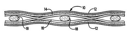
and signal conductors in a bundled cable system. Figure
1 illustrates in a simple schematic form a sectional
view of a preferred shielding member 10 according to
this invention.
14965
.
- 20~73~4
--6--
The shielding member 10 comprises a pair of outer
planar, electrically conductive foil members 12, such as
aluminum or copper foil, and a flat, sheet-like inner
fiberglass scrim 16 and 18 for strength, bonded to the
pair of planar foil members with adhesive 14. The
scrim, a plan view of which is shown in Figure 2,
comprises a majority (at least 10 to 15 strands per
inch) of longitudinal parallel fiberglass strands 16 and
a minority (only 2 or 3 strands per inch) of cross
fiberglass strands 18. The parallel longitudinal
fiberglass strands 16 provide the strength while the
cross fiberglass strands 18 primarily hold the scrim
- together in proper spacing during fabrication. In such
preferred embodiment, a typical foil thickness is about
one mil, with an overall thickness of about 8 mils,
where the scrim and adhesive to secure the foil members
comprise the major portion of the composite.
An important characteristic of bundled cable is
that it must possess relatively high strength and
flexibility. This is especially true of the shield.
High strength and flexibility in the shield is necessary
because this cable, although relatively stiff, must be
pulled through holes in studs in a house, much in the
same manner as conventional non-metallic cable. Since
this cable, a typical ribbon cable being illustrated in
Figure 4, contains additional signal conductors, it is
stiffer than conventional non-metallic power cable.
14965
20~'~33'~
--7--
Therefore, the addition of the shield should not add to
the stiffness of the cable. Furthermore, the addition
of the shield should increase the tensile strength of
the cable, to assist in preventing damage to the
relatively weak signal conductors because of the tensile
stresses imposed as the cable is pulled. By the unique
construction of the shield hereof, the tensile strength
of the bundled cable is enhanced. In addition to
strength, desired attributes of the shield are
resistance to knotting, and tearing when notched or edge
cut.
Figures 3-5 illustrate the general steps in
fabricating a bundled hybrid cable, with shield, as
taught by this invention. In Figure 3, there is shown a
flat ribbon cable 20, as known in the art, containing
plural power conductors 22 and plural signal or data
conductors 24. Such conductors, arranged generally in
parallel relationship, are joined by a common insulation
sheath 26. For purposes of illustration, a typical
ribbon cable 20, such as shown in Figure 3, may comprise
three power conductors consisting of a hot, ground, and
neutra~ wires, and six data conductors to control
various sub-systems.
Figure 4 is a view similar to Figure 3, but showing
the shielding member 10 wrapped around the plural signal
conductors 24. That is, the shielding member is
positioned within the hybrid ribbon cable by folding the
14965
: '
2~7~3~
--8--
shield about a longitudinal fold line and placing one
side of that shield adjacent the signal conductors up to
and around at least one of said power conductors. The
other side of the shield extends around the exterior of
the signal conductors. Thus, the signal conductors are
enclosed around substantially the entire circumference
of that portion of the cable. Thereafter, the assembly
of Figure 4 is folded to make it more compact into a
generally circular configuration, whereupon an outer
sheath 30 such as PVC, is provided, see Figure 5. By
this arrangement, with the shielding member 10 in place,
the signal conductors 24 are shielded from the power
conductors 22.
Figures 6 and 7 illustrate the manner by which the
bundled cable of this invention may be used in home
construction, for example. In Figure 6, there is shown
a section of bundled cable 40 stapled 42, to a stud 44
on opposite sides of a convenience center bracket 46.
This cable section has a loop formed between the two
locations in which it is secured to the stud. Figure 6
shows that this cable can be positioned in this manner
when the cable is initially pulled and positioned within
a wood frame structure of conventional construction,
prior to erection of the drywall in the structure.
Prior to termination, a section of the outer wrap
or sheath 30 must be removed. This may be accomplished
by removing the outer sheath 30 from a section of the
14965
. , .
.'' ~ .
.. ,
~ .
2~5733~
g
cable adjacent each location in which a cable tap is to
be attached to the cable. This sheath can be removed by
longitudinally slitting the outer sheath and then
cutting away this outer sheath at two spaced apart
locations 50,50' (see Figure 7~. The flat ribbon cable,
which is initially in a folded or bundled configuration,
can then be flattened in that section of the cable from
which the sheath has been removed. Prior to flattening
this cable, the shield, which is also in a folded
configuration, is removed from its initial position in
which a portion of this flat shield separates the data
conductors from the larger gauge power conductors.
The conductors in the flat ribbon cable may then be
terminated to a hybrid branch cable tap 52, while the
shielding member 10 is deployed on the rear of the
terminated assembly, see Figure 7.
It may be necessary or desirable to cut and sever
the shielding member lO. In such situation the unique
construction of the shielding member 10 allows for
splicing in a manner that retains the strength and
integrity of such member. That is, by the preferred use
of a shielding member comprising outer layers of a
conductive material, such as an aluminum foil, bonded to
an integral layer including a plurality of
longitudinally extending fiberglass strands, exceptional
strength and notch resistance i5 achieved, as more fully
explained hereinafter. Splicing of the shielding member
14965
20~3~4
--10--
10 may be accomplished by the use of a metallic, V-
shaped member as illustrated in Figure 8a, or
alternatively as illustrated and described in U.S.
Patent No. 4,560,224, assigned to the assignee hereof.
Figure 8a shows a suitable splicing member 60
characterized by a pair of arms 62,62' joined by a web
portion 64. One of said arms, arm 62, for example, is
provided with one, and preferably more, lances 66
directed inwardly toward the outer arm 62'. Said other
arm 62' is provided with a corresponding number of
aligned, lance receiving openings 68, one of each to
receive a lance 66. Thus, in closing the splicing
member 60, i.e. bringing the arms 62,62' toward one
another, with the shielding member 10 therewithin, the
lances 66 are caused to penetrate such shielding member
and enter into their corresponding openings 68. By this
operation, the penetrating lances 66 are caused to
interact with an hold the strands 16,18 of the
fiberglass scrim.
In the practice of this invention, a pair of
shielding members 10 are folded along a longitudinal
axis thereof and interlocked in a manner as follows:
~ , see also the sectional view of Figure 8c.
In a preferred practice of this invention, two splicing
members 60, applied from opposite sides as shown in
Figure 8b, are brought into engagement with the
interleaved shielding member 10 and clamped, such as by
14965
20~7~3~
--11--
the application of a crimping tool thereto. While this
results in formally splicing such shielding members 10
together, it also cuts into and severs isolated
locations along the scrim. Figure 9 shows a formal
splice as it may appear in the wiring of a construction
project.
Recognizing that splicing may be a necessary
consequence on the use of the cable hereof, a series of
tests were conducted to show the significant level of
strength remaining in a shielding member where certain
of the support strands were damaged. For such tests,
two .001" thick dead soft aluminum foils were adhered to !
a fiberglass scrim, where such scrim had from 10 to 15
longitudinally arranged strands per inch, and 5 strands
14965
20~'73t,4
per inch in the horizontal direction. The results
thereof are presented in Table I.
TABLE I
. ....... _... . ~
SAMPLE TENSILE BREAK TENSILE BREAK TENSILE
STRENGTH - w/ .5" EDGE BREAK
lbs (foil) CUT STRENGT~
l E _ _ _ 77
Sample Thickness (Five Points Avg.) 6.9 mils
All tensile strength tests are done with .5"/min head rate.
Sample A and B are the 2" wide composite.
Sample C is 2" wide composite with .5" edge cut.
Sample Dl and D2 are spliced with one double splice and
tensile test was done with the composite folded in
half.
Sample E is spliced with two single splices, and folded for
tensile test.
It is significant from the data of Table I that even
where the shielding member was cut to 25% of its width,
the integrity of said member remained high.
14965