Note: Descriptions are shown in the official language in which they were submitted.
2 ~ :3 rl ~ 1~ 7
1292/US
~one Screw
Field of the Invention
The invention relates to a bone screw for orthopedic use.
Background of the Invention
Bone screws of the type here involved have, theoretically, two
indications or f ields of use. The first involves holding
together two bone fragments in a pre-determined anatom cal
position, particularly in reduction and extension osteotomy. In
this first indication, the bone screw is used alone.
The second indication involves anchoring external setting
components on the bone, e.g. when an external fixation device is
used in osteosynthesis. In this second indication, bone screws
are used within a framework of one or more longitudinal members.
In the first indication, for e~ample in treatment of the under-
developed lower face of a patient, an effort is made to achieve
an operative extension of the lower jaw that will permit a normal
bite. This is done for example, by splittiny the lower jaw and
mo~ing the fragments about. For this purpose an occlusion key is
used as a guide and positioning track for adjustment of the
corpus segment and frontal segment of the jaw. Each fragment is
then fixed with several, preferably three, traction bolts. In
the use of conventional bone screws, tensile forces occur that
prevent precise holding together of the bone pieces in the pre-
2~7~7
determined operating anatomical position. In correction of thelower jaw position, for example, only two holding traction bolts
can be used at the same time on the traction side of the linea
obli~ua, while a third bone screw that would better define and at
the same time hold the position of the fragments relative to one
another is only marginally applicable. Thus, a stable position
of the fragments to one another during, for example, lower-jaw
osteotomy, is not guaranteed. Naturally, the same disadvantages
also occur in other indications in which two bone fragments,
mostly without direct bodily contact, must be knit together.
In the second indication, a bone screw may be used in the form of
Schanz screw, which serves to anchor external setting components
in the bone. The Schanz screws are inserted through small
incisions in the skin and the soft tissue into the bone. The
thread of the Schanz screw prevents axial slippage of the screw
in the bone hole. The actual setting component, the external
fixation device, is mounted on the normally smooth shaft of the
Schanz screw. The principal area of this second indication is
that of open fractures. These fractures cannot be handled by
internal osteosynthesis, since the implantation would cause
additional damage to the soft parts. A disadvantage of this
known method, however, is the permanent linking of the bone with
the "outside world/' through the transcutaneously applied Schanz
screws. The longer these Schanz screws are ~eft in the body, the
greater the danger of a "pintrak infection." Such an infection
is aggravated by the Schanz screws, which are not under tension,
~.~57~7
~ecause these screws promote bone resorption by micro movements.
In an extreme case J such loosening can lead to a sequestration.
Clinical research has shown that a pintrak infection would occur
very rarely if the screw were well anchored in the bone.
In EP-A2 0 369 266 a bone screw is disclosed which between a
smooth shaft part and a threaded part, has a shoulder with
appropriate slope so that a radial pre-tension is created upon
implantation in a tubular bone. In this known bone screw, the
introduction of the screw shaft with its enlarged diameter into
the proximal corticalis of the tubular bone is disadvantageous.
If the thread at the end does not have an adequate hold in the
counter-cortisalis, the anchoring will not be sufficient to draw
the conical expanding screw shaft into the proximal corticalis.
In such a case the threading is torn out, and it is no longer
possible to screw the screw into the bone by axial pressure.
Another problem with this known screw resides in maintaining the
hole diameter tolerance during drilling into the proximal
corticalis. If the drill is not guided properly, an excessively
large hole is created that cannot be radially pre-stressed
sufficiently.
Summary of the Invention
The present invention provides a bone screw designed to overcome
these problems. The bone screw according to the invention
provides, for a first indication, the setting of two pieces of
bone in an anatomically pre-determined position throughout the
2 ~ J~7
healing process and for a second indication an insertion in which
the bone screw can be permanently screwed into an under-
dimensioned hole without damage to the bone, with a sin~le
drilling procedure, with precisely controlled radial compression
of the receiving bone tissue, and with maintenance of the radial
pressure over the entire circumference even under additional
functional loads~
In accordance with the invention these goals are met by means of
a bone screw having a head end, a tip end and a shaft extending
between said ends, said shaft having a first threaded segment
toward the head end, with a minor diameter dl and a second
threaded segment towards the tip end with a minor diameter dz, dz
being less than d1, the thread in said segments having the same
pitch. Preferably a third transition segment is provided between
the first and second segments.
In a preferred embodiment for the first indication the major
diameter of the thread of the second, shaft segment is smaller
than the minor diameter of the first section. Thanks to the fact
that the bone screw has two segments equipped with threads having
different minor diameters, the screw can be anchored in two bone
fragments, which have an opening with a diameter appropriate to
the shaft area in question.
The anatomical distance separating the bone fragments, pre-
determined for screw insertion, is maintained when the bone screw
-- 4
2 3' ~
is screwed in. ~ bone-free cavity existing between the bone
pieces is thereby securely bridged. The transitional sequent in
this embodiment is preferably shorter than or equal to one pitch
of the thread, which appropriately is designed to be self-
cutting, so that the operator can insert the bone screw directly
after the positioning of the necessary hole.
Advantageously, the transitional area between the two threaded
sequences is continuously tapered, e.g. in the form of a cone.
In preferred embodiment for the second indication the shaft has
an additional, smooth, fourth shaft section, connected at its
head end to the first threaded segment.
srief Description of the Drawinqs
The invention will be further described with reference to
the accompanying drawings, in which:
Fig. 1 is a view in side elevation of a bone screw according to
the invention;
Fig. 2 is a bottom plan view of the bone screw according to Fig.
l;
Fig. 3 is a top plan view of the bone screw according to Fig. 1;
Fig. 4 is a view in side elevation of a preferred embodiment of
the bone screw according to the invention; and
Fig. 5 is schematic view of bone screw of Fig. 4 implanted in a
tubular bone.
J 7
Detailed Description of the Invention
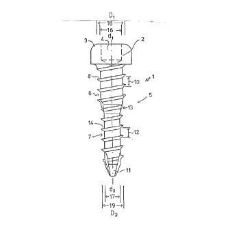
Referring to Eig. 1, a bone s~rew 1 according to the invention is
shown in the form used for setting two bone fragments. Bone
screw 1 can be used particularly, for example, in the operative
extension or shortening of the lower jaw, or the extension of a
limb. Bone screw 1 has a screw head 2, which advantageously has
rounded corners 3. A hexagonal socket 4 is provided in screw
head 2, with which the operating surgeon can position a tool for
easy insertion of bone screw 1.
The bone screw 1 has a shaft 5, which has two threaded segments 6
and 7. The first section 6, connected directly to screw head 2,
is designed essentially as a circular cylinder with a constant
minor diameter 16 (d1). By way of example, minor diameter d~ of
the first shaft section may, in case of a bone screw intended for
a jaw osteotomy, be 9 millimeters. Shaft section 6 has an
external thread 8 with a pitch 10. External thread 8 of shaft
section 6, illustrated in Fig. 1 with three turns, can have a
different number Gf turns for other applications.
The second shaft section 7, is a circular cylinder and is
connected with the first shaft section 6. It has an essentially
constant minor diameter 17 (dz). The second shaft section 7
extends as far as screw tip 11. The minor diameter d2 is smaller
than minor diameter d1 of first shaft section 6. In the case of
a bone screw 1 used in jaw osteotomy, the minor diameter d~ of
the second shaft section 7 might be, for examplP, 6 millimeters,
2~r~r~3~
and thus one-third smaller than the minor diameter d1 of the
first shaft section 6.
The second shaft section 7 has an external thread 14, which,
depending on the length of the second shaft section can have more
or less than the five illustrated turns 14 with proportional
pitch 12. In particular, the minor diameter d2 of the second
shaft section 7 added to the depth of external thread 14 is
smaller than the minor diameter d~ of the first shaft section 6,
so that the second shaft section 7 can be inserted without
touching the walls of the hole provided for the first shaft
section 6 in a bone fragment.
The pitch 12 of the external thread 14 of the second shaft
section 7 is equal to the pitch 10 of the first shaft section 6.
The transitional area 13 between the first and the second shaft
sections 6 or 7 is as short as possible and advantageously less
than the length of a thread pitch 10 or 12.
In a exemplary operation using the screw of Fig. 1, the bone of
the lower jaw is split on both sides. The surgeon then makes two
or three holes in each of the two bone pieces of the corpus and
the forward fragment, the axes of which are in alignment if the
bone fragments are in anatomically correct position. This leads
to a cavity between the bone fragments that must be bridged. The
holes aligned with each other are designed in such manner that
they have different diameters. The diameter of the forward hole
-- 7
~ J~
is larger than that of the back hole. The two holes are made in
a single drilling procedure, with a stepped drill that has the
different diameters. Each bone screw 1 is then inserted, with
its second shaft section 7, the minor diameter d2 of which is
smaller, through the larger hole in one bone fragment; in the
case of jaw osteotomy, the forward fragment. The screw tip 11 of
bone screw 1 now screws into the opening in the other bone piece,
in this case the corpus, the diameter of which i5 smaller,
whereupon, upon appropriate selection of the lengths of the two
shaft sections 6 and 7, the first shaft section 6, which has a
larger minor diameter d1, screws into the opening in the forward
fragment, which has a larger diameter. The insertion is
effectively carried out through the hexagonal socket 4 of screw
head 2, in which the surgeon can insert an appropriate tool to
turn bone screw 1.
Fig. 2 shows a bottom view of the bone screw 1 according to Fig.
1. The difference between minor diameters 16 (d1) and 17 (dz) of
shaft sections 6 or 7 is clearly visible, with minor diameter d2
of the second shaft section 7 together with the exterior major
diameter 19 (D2) of the thread 14 being smaller than the minor
diameter d1 of the first shaft section 6.
Fig. 3 shows a top view of bone screw 1 according to Fig. 1, in
which screw head 2 is illustrated with hexagonal socket 4.
2 ~ P~ 3 ~ 7
The bone screw 1 according to Figs. 1-3 can be ~sed in a variety
of indications, including, in addition to reduction and extension
osteotomy, setting bone fractures, e.g. breaks and ~aults in
limbs.
Another preferred embodiment for a different purpose of a bone
screw according to the invention is shown in Figs. 4 and 5. The
bone screw l illustrated in Fig. 4 consists essentially of screw
head 2, shaft 5, and screw tip 11. Shaft 5 has a head-end,
smooth shaft segment 20 and a threaded segment 6,7. Segment 6,7
consists of a head-end segment 6 having a minor diameter d1 and a
shorter tip-end shaft segment 7 having a minor diameter d2. The
two threaded shaft segments 6 and 7 are connected through a
transitional area 13 with a conically tapered diameter. In this
embodiment, the conical transitional area 13 decreases
continuously from minor diameter d1 to minor diameter d2. The
major diameter Dz of the threaded tip-end second shaft segment 7,
and the diameter 21 (Ds) of smooth shaft segment 20, may be the
same.
The length of the first shaft section of the shaft is dependent
on the absolute dimensions of the bone screw. The increase in
the thread pitch of the thread of the second shaft section is
advantageously between 1.5 and 2 mm, preferably between 1.7 and
1.8 mm.
Referring to the dimensions of the embodiment of Figs. 4 and 5,
the length of the first section is typically between about 60 and
about 80 mm., preferably between about 65 and 75 mm. The length
of the transitional area is advantageously from about 3 to about
7 mm., and preferably from about 4 to about 6 mm. Since the
fault expansion of the bone is around two to three per cent, the
dimensions of the transition area in this embodiment should be
selected in such manner that the ratio d~-d2/d2 is between 0.004
and 0.020, preferably between 0.008 and 0.0~2. An optimal
compression of the bone material can thereby be achieved.
Appropriately, the second, tip-end shaft section has a major
thread diameter of Dz, which corresponds to the diameter Ds ~f
the fourth, head-end shaft section.
In addition, the screw tip is designed preferably to be self-
cutting, e.g. in the form of a trocar or one or more cutting
grooves radially distributed over the circumference.
Appropriately, the threading of the bone screw has dimensions
such that the ratio between the minor diameter d2 and the major
diameter D~ of the second shaft section ranges between 0.89 and
0.95, preferably between 0.91 and 0.93.
To prevent the tip-end section of the thread segment from acting
on the rear corticalis and the transitional segment from acting
on the forward corticalis, both at the same time, which would
lead to loss of control when the bone screw is screwed in, it is
- 10 --
2 ~ 7
advantageous to have the transitional area at a distance of 15-
25 mm, and preferably 18-22 mm, from the screw tip; its length
depends on the absolute dimensio~s of the bone screw, and
typically is between 3 and 7 mm, preferably between 4 and 6 mm.
In a typical screw of the type shown in Figs. 4 and 5 the seyment
6 is 70 mm. long and, the segment 7, 20 mm. The segment 6 has a
minor diameter dl, of 4.65 mm. and the segment 7 a minor
diameter, d2 ~f 4.60 mm. The conical transitional segment is 5
mm. long and tapers conically from 4.65 mm. to 4.6~ mm. The
transitional segment is 20 mm. from the screw tip 11. The major
diameter Dl of the threaded segment 7 is 5.0 mm. which is also
the diameter Ds of the smooth segment 20. The pitch of the
thread of segment 7 is 1.75 mm.
The advantages achieved through the embodiment of Figs. 4 and 5
are essentially that, thanks to the slightly different size of
the shaft section with threading, a desired radial pre-stress is
created in the bone hole, which pre-stress is at least partially
maintained in the bone screw according to the invention even in
case of additional functional loads, so that no relaxation with
consequent resorption of the bone tissue occurs; in addition,
only a single-step drill need be used in order for the two-stage
core of the threaded section of the bone screw according to the
invention to enter the bone hole permanently with a radial pre-
stress but without injury to the bone.
2 ~ r~
Since the radial pre-stress in the bone screw according to the
invention is implemented in the form of an over-sized thread, the
height thereof is precisely defined by the minor diameter of the
thread.
Screw tip 11 of bone screw 1 is designed to be self~cutting, and
for that purpose has several radial cutting grooves 22
distributed over its circumference; it can also be designed as a
trocar tip. The cutting media serve to expar.d the hole in the
bone precisely to the minor diameter of bone screw 1, and
additionally to cut the thread in the bone. For this reason, the
diameter of the core hole in the bone can be slightly smaller
without consequential unintended radial pre-stress when the bone
screw 1 is implanted. If the exact core hole diameter were to be
drilled for the core hole, there would be a danger of an
excessive hole diameter being created by the surgeon through
inaccurate drilling. The use of an over-dimensioned core hole
diameter and the self-cutting screw tip 11 offer the additional
advantage of achieving a "reamer effect, rt in which the hole made
in the proximal corticalis by the self-cutting screw tip 11
corresponds exactly to the required starting diameter for the
subsequent radial pre-stress.
As indicated in Fig. 5, the positioning of the bone screw 1
according to the invention is done by a one-step drilling of the
tubular bone 23,24 with a common drill having a diameter of 4.5
mm, which, experience has shown, creates a hole diameter of 4.55
~ 37 ~ 7
mm. Bone screw 1 with its tip-end shaft segment 7 is now
inserted into this core hole with the customary tools. Since the
minor diameter d2 ~f tip-end shaft segment 7 of thread segment
6,7 is only 4.60 mm, practically no radial pre-stress is created
in the rear corticalis 23.
Only when the head-end shaft segment 6 of thread segment 6,7 with
minor diameter d1 is screwed via the conical transitional section
13 into the forward corticalis is there a radial pre-stress of
0.05 mm, and the end result is as illustrated in Fig. 5.
~- 13 -