Note: Descriptions are shown in the official language in which they were submitted.
,2 a 6 Q 4
APPLICATION FOR PATENT
TITLE: DOWNHOLE ADJUSTABLE STABTT,T7,ER
INVENTORS: WARREN E. ASKEW AND ALAN M. EDDISON
FIELD OF THE INVENTION
This invention relates generally to a stabilizer that is used to center a portion of a drill
string in a borehole, and particularly to a new and improved adjustable stabilizer that can be
5 changed downhole between one condition where it centers the drill string in the borehole and
another condition where it can be tilted with respect to the longitudinal axis of the borehole.
BACKGROUND OF THE INVENTION
It is common to use one or more stabilizers in a drill string to keep the string centered and
10 thereby control the inclination of the hole as the bit drills into the earth. A typical stabilizer
includes a tubular housing having radially extending blades that is threaded into the pipe. The
outer faces of the blades engage the wall of the bore to center the drill string. Where a pair of
properly spaced, full-gage stabilizers is used and one is located near the bit, drilling generally
will proceed straight ahead. If a near-bit stabilizer is not used and the bore is inclined with
15 respect to vertical, the bit will tend to drill along a path that curves downward due the pendulum
effect of the weight of that length of drill pipe which extends downward beyond the uphole
stabilizer. If an undergage stabilizer is used uphole in combination with a full-gage stabilizer
near the bit, the sag in the drill string at the uphole stabilizer tends to cause the bit to drill along a
path that curves upward. Thus to some extent the use and axial positioning of stabilizers can be
20 employed to control the inclination of the borehole in directionally drilled wells.
Another way to change the inclination of a borehole is to use a so-called "bent sub" that
can be positioned in the string, for example, above a downhole drilling motor or between the
CA 0206044~ 1998-10-22
.
motor and the bearing assembly just above the bit. The
conventional bent sub is a length of pipe which has a lower
portion formed at an angle to the upper portion thereof. With
the sub providing a bend in the pipe, the bit will tend to drill
along a path that curves in a plane which contains the two sides
or axes of the bent angle, below the bend point. The bit can be
steered to some extent to the right or to the left by orienting
the plane of the bend with respect to vertical by manipulation of
the drill pipe at the surface. Straight-ahead drilling can be
resumed by superimposing drill pipe rotation over the rotation of
the motor. Although the drill bit will wobble as the bend point
orbits about the axis of the borehole, the overall tendency of
the bit is to drill a straight hole. Precise control over the
borehole inclination can be achieved only where a near-bit
stabilizer is used to keep the bit from wandering as it drills,
for example, through a dipped bedding plane between two rock
strata having different characteristics.
However, the use of a typical stabilizer near the bit
impedes the establishment of a bend angle as described above
because it resists tilting of the rotation axis of the bit. The
blades of the stabilizer engage the wall of the hole for a
considerable length that is full gage, and of course the rock
resists any tilting of the assembly. This can reduce the
effectiveness of using a bend angle to change the course of the
borehole in a predictable manner. Yet a near-bit stabilizer is
considered to be essential for optimum directional control.
An uphole stabilizer that has been proposed for directional
drilling is disclosed in Anderson U.S. Patent No. 4,848,490
issued July 18, 1989. This device uses spiral blades that carry
buttons which can be extended from a minimum to a maximum
diameter in response to downward movement of a mandrel within a
housing that forms the blades. A spring loaded mechanical detent
is used to prevent downward relative movement until a
predetermined axial compressive load is applied. However this
device is not designed for use as a near-bit motor stabilizer,
71511-31
CA 0206044~ 1998-10-22
but rather as an uphole stabilizer which centers the drill string
when the buttons are extended, and which allows the string to sag
when the buttons are retracted. As disclosed, the stabilizer of
the '490 patent does not have many of the features of the present
invention. For example, control over the stabilizer requires the
application of a certain level of axial compressive force, which
can be inadvertently applied during normal drilling operations,
or which may not reach the stabilizer at all in a highly deviated
well due to wall friction on the pipe. Moreover, a mechanical
detent necessarily involves high friction forces, so that
tripping can occur at unpredictable levels, particularly as
inevitable wear takes place. Rotation of the housing relative to
the mandrel cannot occur, so that the stabilizer cannot
automatically resume its maximum diameter position when the drill
string is rotated. Other distinctions also will become apparent.
Other problems also occur in providing near-bit
stabilization that are not appreciated by the above-mentioned
patent. For example, during sliding drilling, the lower portion
of the drill string including the motor housing can undergo
torsional oscillations as the drill string winds up and unwinds
due to variations in weight-on-bit, changes in formation
characteristics, strengths of the rocks, bit wear, type of bit,
and other variables. As used herein, the term "sliding" drilling
means drilling a borehole using only a downhole motor. The drill
string is not turned during this type of drilling, but simply
slides downward as the borehole is deepened by the bit. Such
torsional oscillations can reduce the effectiveness of a variable
diameter near-bit stabilizer unless precautions are taken to
ensure that during sliding drilling the stabilizer remains in its
undergage condition even in the presence of such oscillations.
An object of this invention is to provide a new and improved
near-bit stabilizer that automatically assumes an undergage
condition when a bend angle is being used to directionally drill
a borehole.
Another object of the present invention is to provide a new
71511-31
CA 0206044S 1998-10-22
and improved stabilizer that can be operated downhole in a manner
such that normally retracted, laterally shiftable members are
extended to a full gage diameter in response to rotation of the
plpe string.
Yet another object of the present invention is to provide a
new and improved downhole adjustable stabilizer having wall
engaging means that extend to the full gage of the hole in one
mode of operation, and which retract to a lesser diameter when a
bend angle is present in the drill string above the stabilizer to
enable the rotation axis of the bit to tilt.
Still another object of the present invention is to provide
a new and improved adjustable near-bit stabilizer that will
remain undergage during sliding drilling in the presence of drill
string torsional oscillations.
71511-31
206044~
SUMMARY OF THE ~VENTION
.,_
These and other objects are attained in accordance with the concepts of the present
invention through the provision of a stabilizer apparatus that includes a tubular mandrel having
means at its upper and lower ends for coupling it in a drill string immediately above the bit. If
desired, the mandrel can house the thrust and radial bearings for the shaft that turns the drill bit.
A tubular housing or sleeve is mounted on the mandrel for limited relative rotation and is formed
with outwardly directed blades, each of which carries a vertically arranged set or series of pistons
or buttons that can move between inner and outer positions. The rear faces of some of the
pistons normally engage flat surfaces of the mandrel in a manner such that those pistons are
retracted. Other pistons can be used which are biased outward at all times to provide friction
drag forces against the well bore wall. The mandrel is provided with cam surfaces adjacent the
flats so that when the housing is turned relative to the mandrel in one rotational direction, the
pistons are extended to a full gage diameter. When the housing turns relative to the mandrel in
the opposite rotational direction, the pistons can shift inward to an undergage diameter. When
the pistons are retracted the housing and blades can be tilted to some extent within the borehole
so as not to impede the establicl~ment and use of a bend angle in the drilling process. During
downward movement, the housing is autom~ti~lly rotated to and held in its rotational orientation
where the pistons are retracted. In another embodiment of the present invention, a hydraulic
delay against relative rotation in one direction is provided so that during sliding drilling the
pistons will remain undergage even though the lower portion of the drilling string undergoes
torsional oscillations as the bit drills through the rocks.
BRIEF DESCR~ON OF THE DRAWINGS
The present invention has other objects, features and advantages which will become more
clearly apparent in connection with the following de~ile~ description of preferred embodiments,
taken in conjunction with the appended drawings in which:
Figure 1 is a sche~n~tic view of a well bore having a drill string including a downhole
motor, a downhole adjustable bent housing, the adjustable near-bit stabilizer of the present
invention, and a drill bit disposed therein;
Figure 2 is a longitudinal sectional view, with portions in side elevation, of the present
2~ ~4 ~ 5
.,.--
invention;
Figure 3 is a full cross-section on line 3-3 of Figure 2;
Figures 4-7 are right side only sections taken on lines 4-4, 5-5, 6-6, and 7-7 of Figure 2;
Figure 8 is a developed, external plan view of a blade having a series of stabilizer pistons
5 therein;
Figure 9 is a right side-only cross-sectional view, with some parts exposed in elevation,
of another embodiment of the present invention;
Figure 10 is an enlarged, fragmentary cross-sectional view of a hydraulic delay piston;
and
Figure 1 1 is a developed plan view of the lug and channel control mechanism used in this
embodiment.
DETAILED DESCRIPTION OF P~FERRED EMBODIMENTS
Referring initially to Figure 1, a drill string including a section of drill pipe 10 and a
15 length of drill collars 1 1 is shown positioned in a well bore 17. A downhole motor power section
12 is attached to the lower end of the collars 11, and the lower end of the power section 12 is
connected to a bent housing assembly 13. A near bit stabilizer and bearing assembly 14 that is
constructed in accordance with an embodiment of this invention is attached below the bent
housing assembly 13. A spindle 19 that rotates the rock bit 15 in order to drill the borehole
20 extends out the lower end of the stabilizer 14. Drilling fluids that are circulating by mud pumps
at the surface down the pipe 10 and the collars 1 1 cause the rotor of the power section 12 to spin
and such rotation is coupled to the spindle 19 by a drive shaft having cardan-type universal joints
at each end. The drilling fluids are exhausted through nozzles, or jets, in the bit 15, and circulate
upward to the surface through the annulus 18. The bent housing assembly 13 can be adjusted
25 downhole from one condition where the bit 15 will drill straight ahead, to another condition that
produces a bend angle in the motor housing so that the bit will tend to drill along a curved path.
The assembly 13 can be repositioned in its original configuration for straight-ahead drilling as
desired. Other tools could be used to establish a bend angle
J 4 4 5
.".
either in the housing of the motor 12 or in the drill string thereabove.
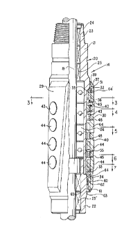
As shown in Figure 2, one embodiment of the stabilizer 14 includes a mandrel assembly
20 having an upper portion 21 and a lower portion 22. The upper portion 21 has a pin 23 with
threads 24 which can be connected to the housing of the assembly 13 thereabove. Upper and
lower radial bearing assemblies shown symbolically as 25 and 25', and a stack of thrust bearings
26, can be mounted inside the mandrel portions 21 and 22 as shown. These bearings function to
rotationally support the spindle 19 which has the bit 15 mounted on its lower end. A generally
tubular housing 30 is mounted on the mandrel 20, and is restrained against vertical relative
movement by the engagement of shoulders 31, 32 near the upper end of the housing 30, and by
shoulders 33, 34 near the lower end thereof.
Splines 35 on the mandrel portion 21 mesh with spline grooves 36 on the upper housing
portion 37 to limit relative rotation. However, as shown in Figure 3, each of the grooves 36 is
wider than its companion spline 35 so that a certain degree of relative rotation can occur. In the
embodiment shown, the housing 30 can rotate clockwise relative to the mandrel 20 through the
angle ~. One of the splines 35' and its groove 36' are considerably wider than the others to
ensurç that the mandrel 20 can be mounted in the housing 30 in only one relative position. A
suitable seal ring 39 (Fig. 2) prevents fluid leakage.
The housing 30 is provided with three outwardly extending blades 29 at equal angular
spacings. The outer face of each blade 29 is wear-hardened, and lies on a diameter that is
slightly undergage with respect to the diameter of the borehole 17 that is drilled by the bit 15.
Each blade 29 has a set of vertically aligned, radially extending bores 40. Received in each set of
bores, from top to bottom, is a drag piston 43 and three stabilizer pistons 44. Of course other
combinations and numbers of pistons could be used. Each of the pistons 43, 44 is sealed by a
suitable seal ring 45 to keep drilling mud out of the inside. As best shown in Figures 5 and 8, the
opposite sides of each of the pistons 44 have longitudinal slots 46, 47 milled therein which
receive the legs 41 of a generally U-shaped retainer member 48 which couples these pistons
together so that they move in unison, and which limits their outward movement. Another shorter
U-shaped member 49 retains and limits outward movement of the drag pistons 43 as shown in
Figures 4 and 8. Each of the drag pistons 43 has a rearwardly opening bore 50 that receives a
CA 0206044~ 1998-10-22
coil spring 51 and a spacer 52. The spring 51 urges the piston
43 outward so that its outer face 53, which is arcuate and
preferably also wear hardened, engages the well bore wall to
provide some frictional resistance to rotational and longitudinal
movement of the housing 30. As shown in Figure 6, a transverse
leaf spring 54 having an outwardly concave mid-portion is mounted
so that its opposite end portions engage and are attached to
outer surfaces of the legs 41 of the retainer member 48, while
its center portion engages an inner wall surface of the blade 29
between adjacent piston bores 40. The leaf springs 54 apply
inward forces to the retainer 48, which cause the rear faces of
the pistons 44 to ride against the outer peripheral surfaces of
the mandrel 20.
As shown in Figures 5-7, flat surfaces 55 are formed on the
mandrel portion 21 so as to extend longitudinally throughout the
region behind each set of the stabilizer pistons 44. The
longitudinal centerlines of the flats 55 are located on 120~
spacings and are orientated relative to the splines 35, the
grooves 36 and the angle ~ such that the flats are located behind
the respective sets of pistons 44 in one angular relative
position of the mandrel and housing, and are not behind them in
another angular relative position. The side surfaces which join
the flats 55 to the cylindrical outer peripheral surfaces 56 of
the mandrel 20 are smoothly rounded as shown to provide
transitions to such surfaces. When the surfaces 56 are behind
the stabilizer pistons 44, these pistons are held in their outer
positions. However, when the sleeve 30 rotates clockwise
relative to the mandrel 20, as viewed from above, the flats 55
are positioned behind the pistons 44 as shown in Figure 7. Thus
the pistons 44 are shifted inward by the leaf springs 54 as their
rear faces 58, which preferably have a cylindrical shape, engage
the faces of the flats 55. When the three sets of pistons 44 are
in on the flats 55 so that the o.d. of the assembly is undergage,
the stabilizer assembly 14 is substantially loosened in the
borehole and can be cocked or tilted to some extent.
71511-31
CA 0206044~ 1998-10-22
The lower section 60 of the housing 30 has an increased
inner diameter to provide an annular wall 61. A compensating
piston 62 is movably arranged between the wall 61 and the
external upset surface 63 of the mandrel portion 22. The
internal spaces between the mandrel portions 21 and 22 and the
housing 30 are filled with a suitable lubricating oil via a fill
port 64 as air is bled out through an upper port 64'. A snap
ring 65 limits downward movement of the compensating piston 62,
and the shoulder 34 limits downward travel of the housing or
sleeve 30. The piston 62 can move longitudinally to provide
compensation for changes in the volume of the oil chamber during
radial piston movement, as well as providing compensation for
changes in hydrostatic pressure and temperature.
As shown in Figures 2 and 8, each set of the pistons 43 and
44 is mounted in a blade 29 having a longitudinal wall 71 on one
side and an opposite sidewall 72 that inclines downward in a
clockwise direction on a helix. As the stabilizer assembly 14
moves downward during sliding drilling the housing 30 tends to
rotate clockwise, as viewed from above, relative to the mandrel
20 due to lateral forces applied by the rock to the outer edge of
an inclined side wall 72. In response to such forces the housing
30 rotates clockwise through the angle ~ shown in Figure 3, until
the sidewalls of the grooves engage the sidewalls of the splines
36. In this rotational orientation, the pistons 44 are radially
positioned opposite the mandrel flats 55 and thus are retracted.
When the motor 12 is placed in operation by starting up the
mud pumps at the surface, the drilling string 10, 11 ~winds up"
to some extent in reaction to the resistance afforded by the
bottomhole rock to rotation of the bit 15. One might expect that
the degree of wind up, which has its maximum amplitude in the
vicinity of the housing of the drilling motor 12, would remain
substantially constant. However, in practice this is not always
the case. In fact the drill string often undergoes back and
forth or oscillating rotations in opposite hand directions, much
like the escapement wheel of a clock, for the various reasons
71511-31
CA 0206044~ 1998-10-22
noted above. Such rotational oscillations are transmitted by the
bent housing 13 to the mandrel 20 of the stabilizer 14, and can
cause the buttons 44 to tend to go in and out, that is alternate
between their full and undergage diameters. To insure that the
stabilizer buttons will remain retracted or undergage during
sliding drilling, the embodiment of the invention shown in
Figures 9 and 10 can be employed.
Here the stabilizer assembly 100 includes a mandrel 101 that
houses thrust and radial bearings (not shown) for the spindle 19
that is attached to the drill bit 15, such bearings and the way
in which they are mounted being substantially the same as shown
in Figure 2. The upper end portion 102 of the mandrel 101 is
threaded at 103 to the lower end of the downhole adjustable bent
housing 13. A sleeve member 104 is carried on the outside of the
mandrel 101 and is formed with a plurality of longitudinally
extending, outwardly directed blades 105. Each of the blades 105
has a vertical row of axially spaced, radially extending bores
106, and each of these bores receives a cylindrical button 107.
The structure of each of the buttons 107, how the vertical rows
of buttons are ganged together for inward and outward, and how
they are each biased inward toward the undergage diameter is
described above respecting the buttons 44 of the previous
embodiment 14 and thus need not be described in detail again.
As shown in Figures 6 and 7 with respect to the previous
embodiment, the mandrel 101 has longitudinally extending flat
surfaces 55 that allow the buttons 107 to shift inward to their
undergage diameter when the mandrel rotates counterclockwise, as
viewed from above, relative to the sleeve member 104, and
cylindrical outer surfaces 56 that position the buttons in their
extended or full gauge diameters when the mandrel 101 is rotated
clockwise relative to the sleeve member. The outwardly biased
drag buttons 43 of the previous embodiment need not be used in
this embodiment, although they could be. It also should be noted
that both of the sidewalls 108, 108' of each blade 105 extend
axially, rather than one side wall being inclined as previously described
71511-31
CA 0206044~ l998-l0-22
The upper end portion 110 of the sleeve member 104 abuts
against an outwardly extending shoulder 105 on the mandrel 101 to
limit upward relative movement of the sleeve member, and an
adapter 111 that is screwed into the bottom of the mandrel 101
provides an upwardly facing shoulder 112 against which a stop
sleeve 113 iS mounted. The upper face of the stop sleeve 113
engages a downwardly facing shoulder 114 on the lower section 115
of the sleeve member 104 to prevent downward relative movement of
the sleeve member. As in the previous embodiment, a floating
piston ring 116 transmits ambient pressures to an oil that fills
all the internal space between the mandrel 101 and the sleeve
member 104.
To rotationally couple the sleeve member 104 to the mandrel
101 in a manner such that the buttons 107 remain retracted during
sliding drilling, even in the presence of rotational oscillations
of the drill string 10, 11, the upper section 110 of the sleeve
member 104 has its inner walls 120 laterally spaced from the
outer walls 121 of the mandrel 101 to provide an internal annular
chamber 122. As shown in clearer detail in Figure 10, a
hydraulically operable delay mechanism in the form of a sleeve
piston 123 iS arranged for axial movement in the chamber 122, and
carries seal rings 124, 125 which prevent any fluid leakage past
the inner and outer surfaces of the upper portion thereof. A
metering passage 129, 129' extends between chamber regions 12 6,
127 respectively above and below the sleeve piston 123. The
upper end of the chamber region 12 6 is sealed by rings 12 8, and a
port 130 and a plug 131 are provided to enable the chamber to be
filled with a suitable volume of hydraulic oil. A flow
restrictor 132 iS positioned in the passage 129 to meter downward
flow of oil in a precise manner, and thus provide a selected time
delay to upward movement of the sleeve piston 123 within the
chamber 122. The opposite side of the sleeve piston 123 iS
provided with another passage 129' (Figure 9) in which a
downwardly closing check valve 145 iS located. The check valve
145 has a low opening pressure, for example in the range of about
71511-31
CA 0206044~ 1998-10-22
2-5 psi differential.
The lower portion 134 of the sleeve piston 123 has external
splines 139 that mesh with internal splines 135 on the upper
portion 110 of the sleeve member 104 so that the sleeve piston
cannot rotate relative thereto. A plurality of circumferentially
spaced lugs 136 project inwardly at the bottom of the sleeve
piston 123 into a companion plurality of channels 137 that are
formed in the outer periphery of the mandrel 101. As shown in
developed plan view in Figure 11, each of the channels 137 has a
helically inclined upper segment 138 that opens downward into an
arcuate lower segment 140. The upper channel segments 138 are
only slightly wider than the lugs 136, which are polygon in
shape, as shown, so that they fit snugly therein during relative
rotation. The lower segment 140 of each channel 137 receives an
inwardly projecting rib 141 on the sleeve member 104 that has a
substantially lesser arcuate dimension than the corresponding
dimension of the channel segment 140. Thus the sleeve member 104
can rotate through a limited angle in a clockwise direction
relative to the mandrel 101, as viewed from above, until the ribs
141 abut against the side walls 142 of the channel segments 140
as shown in dash lines in Figure 11. During such relative
rotation the lugs 136 on the sleeve piston 123 are cammed
downward in the inclined segments 138 to the position shown in
dash lines, which advances the sleeve piston 123 downward in the
chamber 122. During such downward movement, reduced pressure is
generated in the upper chamber region 126 which causes oil in the
lower region 127 to flow upward through the check valve 145 into
the upper region. The low opening pressure of the check valve
145 enables the sleeve piston 123 to move downward without
appreciable restraint. When the ribs 141 abut the side walls 142
of the lower channel segment 140, they will have rotated through
an angle of which can be about 16~. In this position of the ribs
141, the sleeve piston 123 will have moved to the limit of its
downward travel. Relative rotation of the sleeve member 104 in
the clockwise direction is that direction which causes retraction
of the buttons 107 to their undergage positions.
lOa
71511-31
2060~5
, .~,~
When the mandrel 101 rotates clockwise relative to the sleeve member 104, the lugs 136
on the sleeve piston 123 are cammed in the upward direction by the inclined segments 138 of
the channels 137 and thereby attempt to drive the sleeve piston 123 upwardly within the chamber
122. Upward force on the sleeve piston 123 generates high pressure in the oil in the upper
5chamber region 126, which tends to cause the oil to flow downward in the passage 129 via the
flow restrictor 132. The check valve 145 seats to prevent downward flow through the passage
129'. The restricted flow of oil through the passage 129 and the restrictor 132 retards or
restrains upward movement of the sleeve piston 123, and restrains relative rotation of the sleeve
member 104 in the counterclockwise direction, which is the direction that causes extension of
10the buttons 107 to their full-gauge diameter.
If the torsional oscillations of the drill string 10, 11 have an amplitude that does not cause
the ribs 141 to engage the sidewalls 142 initially, the delay me~h~nisrn will nevertheless cause
such engagement to occur after several oscillations. The first time the mandrel 101 rotates
counterclockwise under these circumstances, the lugs 136 will move partially down the inclined
15segments 138 to an intermediate position, and then when the mandrel rotates clockwise the
hydraulic delay will cause the sleeve member 104 to rotate with it. On the next or a subsequent
counterclockwise rotation of the mandrel 101, the lugs 136 will abut the sidewalls 142 and be
hydraulically restrained by the delay there~g~inst. Thus the buttons 107 will shortly come in to
their undergage diameter as sliding drilling is commenced.
OPERATION
The parts of each embodiment are assembled as shown in the drawings to provide acombination bearing assembly and near-bit stabilizer 14 or 100 that is connected in the drill
string immediately above the bit lS and below the housing 13 of the downhole motor 12. In the
25embodiment shown in Figure 2, one or more of the outwardly biased drag pistons 43 engage the
wall of the borehole, however the stabilizer assembly 14 can be tilted somewhat because of the
diametrical clearance provided when the pistons 44 are in their retracted positions. During
downward movement the drag of a helical side surface 72 of a blade 29 against the borehole wall
exerts clockwise torque which maintains the housing 30 in the orientation where the buttons 44
30are retracted as shown in Figure 7. If a bend angle has been established by operation of the bent
11
CA 0206044~ 1998-10-22
housing assembly 13, the ability of the stabilizer 14 to tilt in
its undergage condition allows full utilization of the bend angle
in influencing the path of the drill bit 15.
When a bend angle is being established in the bent housing
apparatus 13, which involves rotation of the drill string to the
right, the spring-loaded buttons 43 provide frictional restraint
which resists rotation of the housing of the assembly 13. After
some degree of relative rotation, the stabilizer mandrel 20 also
will be rotated to the right. Relatively speaking, the housing
30 is rotated counter-clockwise through the angle ~, permitted by
the excess width of the spline grooves 36, to the orientation
shown in Figure 3. This positions the outer surfaces 56 on the
mandrel 20 behind the pistons 44 as shown in Figures 5 and 6 and
causes momentary extension thereof. However, as soon as sliding
drilling is commenced, the housing 30 rotates clockwise relative
to the mandrel 20 due to engagement of an edge 72 with the well
bore wall, which causes the flats 55 to be positioned behind the
buttons 44. In addition, reactive torque as a result of
operation of the motor 12 also tends to produce counter-clockwise
rotation of the housing 30. Thus, the buttons 44 are shifted
inward to their undergage positions by the springs 54. Again,
this permits a bend angle that has been established in the tool
13 to be fully effective in influencing the path of the drill bit
15. Any time that the stabilizer 14 is moved upward in the
borehole, the inclined side walls 72 do not tend to cause
rotation of the housing 30, so that the pistons 44 can remain on
the flats 55 and cause the stabilizer to remain undergage. The
feature is particularly useful when the drill string is being
withdrawn from the well.
It will be recognized that the inclined blade surfaces 72
induce a clockwise rotation of the housing 30 and retraction of
the buttons 44 only in the sliding drilling mode, so that where a
bend angle is being used the bit 15 is not subjected to excessive
side loads which can cause the motor 12 to stall. If a
directional drilling procedure is used where rotation of the
12
71511-31
CA 0206044~ 1998-10-22
drill string is superimposed over that of the motor 12, the
stabilizer 14 automatically assumes its full gage condition
because the housing 30 will be rotated counter-clockwise relative
to the mandrel 20 to the orientation shown in Figure 3. In this
position the buttons 44 are cammed outward from the flat surfaces
55 onto the larger diameter surfaces 56 of the mandrel 20 as the
housing 30 rotates relative to the mandrel 20 so that the
stabilizer assembly 14 is full-gage.
The present invention finds particular application in
various drilling procedures. Where the bend assembly 13 is
straight and the pipe string 10, 11 is being rotated, the
stabilizer 14 becomes full gage to center the bit 15 in the
borehole. When the assembly 13 is adjusted to provide a bend
angle and sliding drilling is being carried out, the stabilizer
14 au~comatically assumes its under-gage condition for more
accurate control over angle build-up rate. Of course where the
assembly 13 is straight during sliding drilling, the stabilizer
14 also remains undergage to provide a slightly dropping
inclination angle under circumstances where this might be
desirable. Finally where the assembly 13 produces a bend angle
and the pipe is being rotated, the stabilizer 14 becomes full-
gage. However, this later procedure can produce high cyclical
stresses in the apparatus at and near the bend point which might
cause damage to the downhole tools if continued over an extended
period of time, and should be avoided unless a special bend
assembly 13 is used.
The embodiment shown in Figures 9-11 operates as follows.
Where rotation of the drill string 10, 11 is superimposed over
the rotation of the power section of the downhole motor 12 in
order to drill straight ahead, the stabilizer assembly 100
automatically goes to its full-gauge condition to provide packed-
hole type of drilling tool string. This is because there will be
a continuous drag of at least one of the blades 105 against the
low side of the borehole which produces counterclockwise torque
on the sleeve member 104. Such torque forces the sleeve piston
13
71511-31
CA 0206044~ 1998-10-22
123 upward in the chamber 122 as the lugs 136 move up the
inclined segments 138 of the channels 137. The sleeve piston 123
can shift upward very slowly as hydraulic oil meters through the
restrictor 132. When the ribs 141 abut against the sidewalls 142
of the channel segments 140, the sleeve member 104 will have
rotated fully in the counterclockwise direction to the relative
position where the buttons 107 are extended to the full gauge
diameter.
When superimposed rotation is stopped and sliding drilling
begins, the buttons 107 will be shifted inward to their undergage
positions. As mentioned above, the drill string will undergo
torsional oscillations due to various factors, the amplitude of
such oscillations being maximum in the vicinity of the drilling
motor 12. Of course the housing of the motor 12 is connected to
the mandrel of the bent housing assembly 13, and the housing of
the assembly 13 is connected to the mandrel 101 so that such
oscillations are transmitted to the mandrel 101. Each time the
mandrel 101 turns counterclockwise and the sleeve member 104
remains stationary, the sleeve piston 123 is pulled at least
partially downward as oil flows substantially freely through the
check valve 145. Each time the mandrel 101 rotates clockwise,
the sleeve member 104 again remaining stationary, upward movement
of the sleeve piston 123 is hydraulically retarded. Thus the
sleeve member 104 will be moved to its full clockwise relative
position on mandrel 101, as shown in Figure 7, where the buttons
107 are retracted. In this position the stabilizer assembly 100
is undergage and will not impede the use of a bend angle in the
assembly 13 in directionally drilling the borehole.
It now will be recognized that new and improved downhole
adjustable stabilizers have been disclosed which meet the
objectives and have the features and advantages of the present
invention. Since certain changes or modifications may be made in
the disclosed embodiment without departing from the inventive
concepts involved, it is the aim of the appended claims to cover
all such changes and modifications that fall within the true
spirit and scope of the present invention.
14
71511-31