Note: Descriptions are shown in the official language in which they were submitted.
2 ~ 7
This invention relates to dispensers for liquids and
more particularly to dispensers used domestically to store and
dispense such varied products as vinegar, hair shampoo, ketchup,
etc.
The invention will be described primarily with
reference to consumer products used domestically, but does have
application to dispensing liquids from larger containers used in
commercial establishments.
Smaller quantities o products in liquid form have for
many years been packaged in a variety of containers suitable for
shipping, displaying, handling and eventual point-of-purchase
sale. Historically, the most common container has been the
glass bottle which can be made in a variety of shapes and sizes
and with different types of closures. More recently, however,
glass containers have been displaced to some extent by
containers of synthetic plastic materials which can be moulded,
blow-moulded and generally formed into a great variety of shapes
and sizes. Also, because of the nature of plastics materials,
closures for these containers can be of many varied types
ranging from simple screw-caps similar to those used with glass
bottles, to flip tops and valved openings.
A further development has been the introduction of
dispensers into the marketplace resulting in a growing impetus
to use these dispensers wherever possible. The major
characteristic of a dispenser when compared with a simple
container is that a dispenser can be activated in some way to
provide some of its contents without the need to remove caps or
closures, and in some cases without even lifting up the
~2~
dispenser. This invention provides an improved dispenser which
can take a variety of forms.
There have been a number of approaches to the design of
dispensers for domestic liquid products, and they fall into
three main groups. Firstly, there is the simple device which
allows the dispenser to be lifted and tilted to allow some of
the contents to fall under the influence of gravity from the
dispenser before the dispenser is again held upright to stop the
flow. Dispensers of this type are used as attachments to
bottles of liquor to permit a particular volume of liquor to be
dispensed with each tilt of the bottle.
A second approach is to provide some mechanical device
which, when activated, forces some of the liquid out of the
dispenser. An example of this would be trigger dispensers which
incorporate a pump actuated by the trigger to force some of the
contents out of the dispenser. This requires some manual
dexterity as well as the application of some force to do work on
the dispenser.
The third type of dispenser involves the use of stored
energy. An exa~ple of this would be an aerosol which contains a
gas under pressure, or in some instances, a stretched bladder
containing the contents so that the operation of a valve will
allow the energy from the bladder to displace some of the liquid
contents out of the dispenser.
Of these three types, the present invention falls into
the category of a dispenser which requires the application of a
force to displace some of the liquid.
2 ~ 7
The design of all dispensers must meet numerous
criteria which are to some extent conflicting. From the
standpoint of appearance on a shelf for sale, it is generally
accepted that the overall impression given by the dispenser will
affect the sales. If the dispenser matches the image projected
by the product, then this seems to have an effect on purchases
and on the success of the product. On the other hand, the
dispenser is a throw-away item so that the cost of the dispenser
must be kept to a minimum in order to be competitive in the
marketplace.
This cost consideration is of course dependent on
complexity so that the less complex the dispenser the more
acceptable it would be in terms of the cost of production. It
is therefore a challenge to design a dispenser which is both
appealing to the eye when containing a particular product and
also inexpensive to manufacture while of course operating
adequately once the purchaser has started to use the product.
Once the product is purchased and taken to the
consumer's home, there are important considerations for the
consumer. Firstly the product must function or be useful in the
manner anticipated by the purchaser. However, the dispenser
containing the product also comes into play because if it is
di~icult to use, or unreliable in any way, then it may affect
the purchaser's decision whether or not to buy the same product
again. Reliability includes a number of possible difficulties,
but high on the list would be a dispenser which does not
dispense cleanly and which possibly drips or allows liquid to
soil the outside of the container between uses. This has led to
a ~ '~
the development of a large number of valved dispensers having
designs of valves which are intended to cut off the flow clearly
and without dripping and soiling while there is no doubt that
suitable structures have been developed, they do add
significantly to the cost of the dispenser. As a result
attempts have been made to simplify dispènsers by eliminating
the valving. Such attempts have resulted in difficulty because
once the valve is removed temperature fluctuations can drive the
contents out of the dispenser with a resulting tendency for
dripping. Also, the actual dispensiny is less than adequate in
many instances.
Synthetic plastics materials also lend themselves to
the manufacture of dispensers which have flexible bodies to
allow deformation to apply pressure to the contents. This form
of dispenser, while avoiding the use of a trigger, nevertheless
continues to need the valve which commonly involves some form of
closure which is opened before dispensing and closed after
dispensing~
The present inventor taught the use of dispensers which
have no moving parts and which satisfy the requirements of clean
dispensing with temperature compensation to permit the dispenser
to be placed in various locations within a designed temperature
range without inadvertent dripping or dispensing caused by these
temperature variations. Such structures are taught in U.S.
Patents 4,324,349, 4,635,828, 4,645,097 and 5,033,653. The
dispensers include a reservoir containing some of the liquid to
be dispensed and in communication with the main part of the
dispenser in the form of a container where the major volume of
e~
the liquid is contained. Air is trapped above the liquid in the
container under a negative pressure which prevents the liquid
flowing through the reservoir and out through a discharge
passageway. ~hen pressure is applied to the contents, the
negative pressure is overcome so that liquid will flow through
the reservoir and out via the passageway. As soon as the
pressure is released, a negative pressure is created by the
walls returning from a deflected condition to the original
condition so that air is sucked back into the passageway and
reservoir to set up a condition of equilibrium. As the air is
sucked back, liquid is cleaned out from the passageway and some
of the air finds its way through the liquid to finish above the
liquid in the container and some remains in the reservoir. It
is the air in the reservoir which effectively provides the
temperature compensation. As temperature increases, the
negative pressure above the liquid in the container becomes more
resulting in some flow into the reservoir and liquid will
consequently rise in the reservoir and displace air out o the
passageway.
U.S. Patent Serial No. 5,033,653 is an improvement over
the earlier Kaufman patents in that this patent teaches
structures in which the parameters of response rate and
temperature compensation are made essentially independent
compared with the earlier patents in which the parameters were
interrelated.
According to U.S. Patent No. 5,033,653 a dispenser for
liquids is provided having a container for holding liquid at
levels above a predetermined level, and including means to vary
~7
the pressure in the container. An outlet is provided at a level
below the predetermined level and a reservoir is in fluid
communication with the container. The reservoir defines an air
relief opening to permit pressure changes caused by temperature
fluctuations to be equalized with atmospheric pressures and a
discharge passageway is provided in fluid communication with the
container to lead liquid from the container to the outlet when
said means is used to increase the pressure in the container.
The present invention is an improvement over that structure and
is intended to provide an inexpensive structure which is readily
disassembled for refilling or washing.
The invention will be better understood with reference
to the drawings and associated description wherein:
Figs. 1 to 3 are diagrammatic representations of a
dispenser according to the invention in use;
Fig. 4 is an isometric view with portion broken away to
show parts of a preferred embodiment of dispenser according to
the invention; and
Fig. 5 is an exploded isometric view of parts of the
dispenser.
Reference is made first to Fig. 1 which illustrates
diagrammatically a dispenser 20 made up of a container 22 with a
closed end 24 uppermost and having an opening 26 at the
lowermost end within a reservoir 28. The opening 26 is within
the reservoir and spaced from a bottom 30 of the reservoir
sufficient to permit liquid 32 from the container 22 to flood
into the reservoir. The flow will be arrested when the pressure
in a space 34 above the liquid 32 reaches a negative pressure
2 ~ 7
sufficient to balance the column of liquid in the dispenser.
This is explained in detail in previous Kaufman patents
mentioned earlier.
A passageway 36 extends from adjacent the bottom 30 of
the reservoir to an outlet 38 where liquid is dispensed. A
small hole 40 is provided in the wall of the passageway 36 and
communicates with the reservoir for purposes which will be
explained.
In the Fig. l condition, liquid is in a stable
condition and will remain as shown unless the dispenser is
activated or i~ affected by temperature fluctuations. In the
event that the temperature increases, then the negative pressure
in the space 34 will be affected with the result that a level 42
of liquid in the reservoir will move upwardly. The annular
space about a neck 43 of the container 22 is sufficient to
accommodate this movement over a wide range of temperature
fluctuations. The space above the level 42 in the reservoir is
at ambient pressure due to the small hole 40 communicating by
the outlet 38 to atmosphere.
The reservoir shown in Fig. l is activated by applying
manual pressure to the closed end 24 to deflect a bellows 44
formed in the wall of the container. This affects the pressure
in the space 34 and causes the liquid level 42 to rise. This
can be seen by comparison of Figs. l and 2 where a deflection
~a~ has taken place in Fig. 2. Because the hole 40 is small,
air from above the level 42 in the reservoir will not move
quickly under the effect of the activation of the dispenser
because there is an escape for the pressure via the passageway
~2~ 7
36. Consequently the change in the pressures within the
dispenser is accommodated by liquid moving through the
passageway 36 and out through the dispensing outlet 38. There
will of course ~e a pressure differential across the hole 40 but
this is insufficient to cause significant flow o air.
Once the dispensing has taken place, the user releases
the end 24 and the resilience in the bellows 44 causes the
dispenser to move towards the Fig. 1 position. An intermediate
position is shown in Fig. 3. In this case, air will move back
into the dispenser and some will find its way through the hole
40 into the space above the level 42. This will tend to assist
in having liquid clear the reservoir and return to the container
due to the fact that the container is the driving force in
having the liquid return. Also, because of the rush of air in
the outlet 38, there will be a cleansing effect which will
remove liquid from this part of the dispenser and limit the
possibility of dripping after dispensing.
The foregoing description of operation of this type of
dispenser involves the present invention which is an improvement
over the structure shown in U.S. Patent No. 5,033,653. The
improvement structure will now be described with reference to
Figs. 4 and 5.
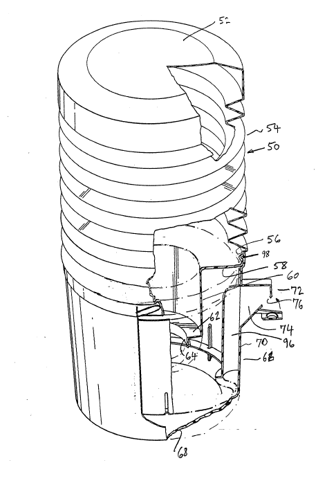
As seen in Fig. 5, a container 50 has an end 52 and a
wall in the form of a bellows 54. The bellows ends at an
annular portion 56 which in turn leads to a radial wall 58 which
meets a cylindrical portion 60 terminating in a second radial
wall 62, which in turn is connected to a neck 64.
The cylindrical annular portion 56 of the container is
2 ~
connected (by means which will be described) to a cup-shaped
base 66 having a bottom 68 and a slightly conical side wall 70.
The angle on the side wall is small and in the order of 2
degrees.
5The base 66 is moulded to include an outlet structure
72 which projects radially outwards to form a small chamber 74
and outlet opening 76. AS can be better seen in Fig. 5, the
outlet structure 72 receives a pivoted closure 78 having a
cylindrical plug 79 which can engage the opening 76 ~Fig. 4)
10when the closure is pivoted upwardly into engagement with the
outlet structure 72. This can be used to close the dispenser
for shipment or in general, to contain the contents when the
dispenser is moved. In normal use, the closure 78 will simply
hang out of the way as shown in Fig. 5.
15As also shown in Figs. 4 and 5, within the cup-shaped
base 66 is a sleeve 80 which also is generally cylindrical but
actually has a small conical shaping to the side wall 82. This
is also of the order of 2 degrees to match the similar shaping
of the base 66. Consequently when these two parts are engaged,
20because the outer wall of the sleeve 80 is a close friction fit
within the base 66, the fit will cause a seal between the two
parts as they engage in face-to-face relationship.
The sleeve 80 is shaped with an external axial recess
84 which extends from a bottom lip 86 towards the top 88 of the
25sleeve but terminates short of the top. A small hole 90 pierces
the sleeve to communicate from within the recess 84 to the
inside of the sleeve. Three location slots 92 are provided at
the periphery of the sleeve and spaced irregularly so that they
will meet location buttresses 94 in the bottom of the base 66 to
permit engagement of the sleeve within the base in one position
only. This position ensures that the recess 84 is in alignment
with the outlet structure 7~ as shown in Fig. 4.
The rest of the struture will be described with
reference to assembling the dispenser. The closure 78 is a snap
fit on the outlet struture 72 and can be assembled first. Then,
the sleeve 80 is dropped into the base 66 and moved to bring the
alignment slots 92 into engagement with the corresponding
buttresses 9~ whereupon the sleeve can be pushed into frictional
engagement inside the base to form a seal between the two parts
except for where the recess 84 is positioned. This recess then
combines with the inside surface of the side wall 70 of the base
to form a passageway 96 shown in Fig. 4.
The resulting sub-assembly is then attached to the
container 50 and to this end, the annular portion 56 of the
container is moved into sealing engagement with the base 66 and
locked in place by threaded engagement between four inner
projections 98 formed on the inner surface of a peripheral ring
lO0 which forms an integral part of the base 66. These
projections engage in corresponding depressions in the container
and these depressions angled on a helix so that as the container
engages the projections 98 it can be rotated to bring it into
tight and firm engagement with the base to seal the container to
the base.
An example of how these parts interrelate can be seen
in Fig. 4 where one of the projections 98 is engaged in the
aforementioned depression in the container 50. Any suitable
- 10 -
arrangement of mating parts will be sufficient to cause a seal
at this point. It is important to note that the seal is not
essential to the operation of the structure although if the seal
is very poor, then there would be sufficient leakage to cause
problems after several dispensings.
It will now be apparent that the dispenser is extremely
simple and that there are a minimum of critical dimensions. The
simplicity of engaging a sleeve 80 within a base 66 to define
the passageway 96 means that the structure can be disassembled
and put in a dishwasher to clean it. This is a very important
consideration for domestic us.
In use, the assembly will of course be completed with
liquid in the container 50. The container is first opened and
held in an upright position with the neck uppermost and the
sub-assembly of the base 66 and sleeve 80 engaged in an inverted
position. Once the engagement is complete, the dispenser is
then rotated into position shown in Fig. 4 and is ready for
use. The first dispensing may have a slow response time, but
once the liquid has established its levels, then the response
will be very quick and a small movement of the end 52 to deflect
the bellows 54 will result in dispensing. As mentioned with
reference to Figs. 1 to 3, the structure then defines a
reservoir 28 having a level 42 of liquid and the operation is as
described with reference to Figs. 1 to 3.
Although the invention has been described with
reference to a preferred embodiment, other embodiments are
- within the scope of the invention. In general, the
establishment of a liquid level in a dispenser as illustrated in
ril
Fig. 1 is the first step and this can be disturbed by any
pressure fluctuation within the dispenser. For instance, if
pressure were applied to the space in the reservoir above the
level 42, then this would cause dispensing. Similarly, if
pressure were applied to the reservoir itself by deforming the
reservoir then this would also result in dispensing. In other
words, any arrangement whereby a change in the internal pressure
results in a loss of negative pressure in the space 34 above the
liquid will cause liquid to move towards the outlet 38 and
dispense from the structure.
Such embodiments are within the scope of the invention
as claimed.