Note: Descriptions are shown in the official language in which they were submitted.
E'J,NDD-9053
~ 3
APP~RATUS AND METHOD FOR NON-STOP SWITCHING
IN ASYNCHRONOUS TRAMSFER MODE
,
BACKGRO~ND OF THE l~V~NlION
l. ~IELD OF THE l~v~NllON
The present inven-tion relates to an appara-tus
and a method for non-stop switching a slgnal ~rom a
current system to a spare system under a PCM
transmission system. More particularly, this invention
is concerned with an apparatus and a method for non stop
switching in which the digital network is duplicated to
ensure instantaneous switching when a fault occurs.
A method called asynchronous transfer mode
(hereafter, ATM) has been proposed as a technological
element for implementing a broad-band ISDN in recent
years. The ATM is a method of segmenting user
information in fixed-length transfer units referred to
as cells of about 50 bytes, then txansmitting the cells
to the destinations in a network that are specified in
the address headers o~ the cells at high speeds.
Accordin~ to the ~TM, unlike conventional packet
swi.tching, information n ed notito temporaril~ placed in
a memory but can be transfe~red at high speed~ in c~
units merel~ by interpreting the cell headers. A ~low
control t error recovery control, and other protocols are
not implemented, permitting the high-speed transfer of
cells.
The ~TM, in which cells are allocated
depending on presence or absence of user informa~ion,
permits c~ml1nication at any transmission speed and
facilitates efficiency in information transmission
despite burst traffic. A unified infsrmation unit or a
cell is employed, helping realized multlmedia
com~unication of divers~ly-foxmatted information
effortlessly and economically.
2. DESCRIPTION OF THE REI~TE~ ART
2~
On a digital network, since signals are
usually highly multiplexed, a ~ault in a signal affects
a wide region of the network. Therefore, a transmission
system or switching apparatus is designed to have a
redundant configuration to ensure system reliability.
The redundant configuration is made up of one spare unit
or line for m current units or transmission lines. When
a fault occurs in a unit or line, the unlt or line is
replaced with a spare. However, in a system for
pro~iding complex and quick services over a digital
network, a duplex standby configuration is usually
adopted because of the ease by which it can be
controlled.
In the duplex standby configuration, a spare
system is placed in hot-standby state and operated in
the same manner as a current system at all times. If a
fault occurs in the current system, the data of both
systems is compared in bits. This facilitates
efficiency in fault detection~ In the case of an
occurrence of a fault, the current system is switched to
the spare sys-tem instantaneously. This helps improve
the reliability of a transmission system. In
conventional transmission ~ervices since a
continuous-bitstream oriented (CBO) service is prov.ided,
an informa~ion stream flow~ at a constant speed w.ithout
fluctuat.ion. In packet switching or synchronous
transfer mode tsrrM)t store-and-~orward switchiny is
performed using processors at end offices. Therefore,
phase control and oth~r supports can be provided at the
end offices, and even if a phase lag is existent between
information -transmitted from the spare system and that
from the current system, switching does not cause
daterioration in information quality such as duplication
of signals or missing signals.
However, in an ATM transmission system, for
example, user information is transferred in fixed-length
blocks or cells, which are dynamically allocated in
3 ~ 63~
response to time-dependerlt vaxying users~ requests ~or
information transmission. Therefore, even if quick
switching is performed in a selector device, part of a
cell~segmented signal is likely to be missing. In
addition, since intervention of protocols in a
transmission network is m;n;m; zed to ensure the
high-speed transfer of cells, a phase difference between
spare and current systems cannot be easily removed. Not
only a missing cell-segmented signal occurs bu~ also a
signal may be duplicated and transferred if switching is
done according to incorrect timing. This may change the
contents of other cell data and cause a variety of
unfavorable e~fects.
SVMMARY OF THE INVENTION
The principal object of the present invention is to
solve the foregoing problems and provide an apparatus
and method for non-stop switching in which a
transmission line for transmitting statistically
multiplexed cells can be switched from a current
transmission line to a spare without causing momentary
in-terruption.
Other object of the invention is ko provide an
apparatus and method for non stop switching in w~lich,
even when a phase dif~erence is existent between current
and spare syskems, the phase difference can b~ absorbed.
In accordance w.ith -the present i.nventi.on, there is
provided an apparatus for switching a current
transmission line transmitting a series of statistically
multiplexed information cells to a spare transmisslon
line hot-standing-by, wherein the information cells
transmitted in the current and spare transmission lines
include empty cells not including user information,
comprising:
a detection means for detecting the empty cell
in the current transmission line and the spare
transmission line,
a determination means for determining a timing
- 4 ~
for switching, based on the -timing of the detection in
the detec-tion means, and
. . .a switching means for switching from the
current transmission line to the spare transmission line
at the timing determined in the d~termin~tion means.
In accordance with the present invention, there is
also provided a method of switching a current
transmission line transmitting a series of statistically
multiplexed information cells to a spare transmission
line hot-standing-by, wherein the information cells
transmitted in the current and spare transmission lines
include empty cells not including user information,
comprising the step of:
detec-ting the empty cell in the current
transmission line and the spare transmission line;
determ;n;ng timing for switching, based on the
timing of the detection in the detection means, and
switching the current transmission line to the
spare transmission line at the timing determined in the
deter~;ning step.
BRIEF DESCRXPTION OF THE DRAWINGS
Figure l is a diagram for explaining the principles
of the present invention;
Figures 2A and 2B are diagrams showing switching
timings in an apparatus for non-stop switching according
to an embodiment o~ the present invention;
Figure 3 is a diagram showing a switching timing
according to other embodiment of the present invention;
Figure 4 is a diagram showing a timing for
switching a series of cells data in which a phase
difference is existent similar to Figure 3;
Figure 5 i5 a diagram showing a timing for
switching a series of cell da~a in which a phase
difference longer than a unit cell transfer time is
existent; and
Figure 6 is a diagram showing a timing for
switching a series of cell data using a buffer under the
5 ~ .3
same conditions as Fiyure 5.
DESCRIPTION OF THE PREFERRED EMBODIMENTS
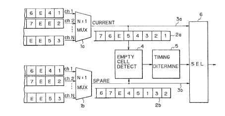
. The principles o~ the present invention will be
described in conjunction with Figure l. In Figure l, N
channel signals transmitted in cells are statistically
N multiplexed in fixed-length cells by current and spare
statistical multiplexers (hereafter, MUX) la and lb,
then transferred as serial cell data 2a and 2b ovex
transmission lines 3a and 3b.
Thus, the series o~ cell data 2a and 2b are
transmitted over the transmission lines 3a and 3b.
Herein, info.rmation cells belonging to each channel, for
example, information cells l, 4, and 6 belonging to a
channel l are transmitted in that order over the
transmission lines 3a and 3b. This is true for both
current and spare systems. However, information cells
belonging to different channels, for example,
information cell l of the channel l and information
cell 2 o~ the channel 2 are transmitted in different
orders between the current system and the spare system.
This is because although the spare system is operated in
a hot-standby state, namely, operated under the same
condit.ions as the current system, a slight difference of
delay times caused ~y the dif~erenco of cable lengths
alters the handling sequence when a conges~ion occurs
among cells of different channels. ~his results in a
di~erent timing o~ ~etching cells during statistical
multiplexing. As a result, multiplexed cells are
arranged in di.fferent orders between the current and
spare systems.
Since a series of information cells is
intentionally or unintentionally intermittent, it,
consequently, contains empty cells denoted with "E"s,
which do not include user information.
An empty cell detector 4 for detecting an empty
cell signal detects the empty cell. A timing
determination Wlit uses an empty cell detec~ed by the
3~
-- 6 --
empty cell signal detector 4 as a tri.gger and determines
a timing for switching transmission lines 3a and 3b.
. According to the switching timing, a selector (SEL)
6 switches a current transmission line 3a to a spare
transmission line 3b, then outpu-ts N-multiplexed serial
cell data without causiny momentary interruption.
Figures 2A and 2B show a timing for switchiny input
cell data from current cell data to a spare using a
non-stop switching apparatus (hereafter, SEL) according
to an embodiment of the present invention, in the case
where a time lag is not existent between the current and
spare system.
A non-stop switching apparatus 7 shown in
Figures 2A and 2B function as the empty cell signal
detector 4, the timing determination unit 5 and the
SEL 6 shown in Figure l. In Figure 2Ar an output of an
MUX la passes through a transmission line 3a, enters the
SEL 7, then goes to an output line 7a of the SEL 7.
Then, the output is separated into N channel signals b-y
an N-channel demultiplexer (hereafter, DMUX) 8. On the
other hand, as shown in Figure 2B, if the current
transmission line 3a is switched to a spare transmissi.on
line 3b, when empty cells are detected both i.n cur~ent
and spare systems, a sexies of cell data enterillcJ the
DMIJX 8 via the Ol1tpUt line 7a of the SEI, 7 ls output as
a separated channel slgnal simllar to that provided
dur.ing non-switchin~ transmission.
Cell data in current and spare systems are fixed-
length cell data with destination information added to
3Q the headers of the cells. If the traffic of cell data
transferred in, for example, an ATM apparatus is about
70%, both the current and spare cell data arrays contain
empty cells even after they are N-multiplexed by a
multiplexer (hereafter, MUX). When no time lag is
existent between the current and spare cell data arrays,
an empty cell is expected to occur simultaneously in
both current and spare systems, because the existence of
~?5 ~
an empty cell means no cell conges~ion. Therefore, both
current: and spare empty cells may be detected
simultaneously according to a specific timing The MUX
outputs input cell da~a in -flrst-in ~irst-out. When
cell data enters the current and spare systems in
channels, a phase shift occurs. This resulks in
different orders of cells between the current
transmission line 3a and spare transmission line 3b.
However, The D~UX 8 identifies each cell data according
to the destination information of the header, then
reproduces a signal. Therefore, the difference in cell
data allocation between both the transmission lines 3a
~ and 3b poses no problem, as ~ax as a spare system is
concerned and the same cell data as those in a current
system have already reached the SEL 7 before the empty
cell data is output.
In this embodiment, current and spare systems are
switched on boundaries of empty cell data. Therefore,
cell data can be transmitted over the output line 7a vf
the SEL 7 without causing a duplicate or missing signal
before and after switching. During switching, empty
cell data is inserted ~o pad inter-cell time slots.
Figures 3 and 4 show timings -Eor switchirlg cell
data in which a time lag is exis-tent. Figure 3 shows
transmission sta-tes before and after switchi.ng, wher~in
empty data .is fir~t detected in a cell on ~he current
transmission line 3a. I~ empty cell data cannot be
si.multaneously detected i.n the current and spare
transmisslon lines because of a time difference between
the current and spare sys-tems, a switching timing cannot
be determined so that the SEL 7 will be switched on
empty cel]. boundaries as described in Fig~re 2. As
shown in Fi.gures 3 and 4, when an amply cell is detected
either in the cuxrent system or in the spare system,
another empty cell is lnserted into the systems. Then,
a -temporary storage; such as, a buffer memory is
installed in the SEL 7 to temporarily store the spare
- 8 - 2~?5~3~
cell data immecliately after an ~mpty cell is detected in
the cell data on either the current or spare
transmission line. As shown in Figure 3, if an empty
cell is detected eaxlier in the current systsm, an empty
cell going from the spare system to the SEI, 7 is saved
in the buffer temporarily. Then, the transmission lines
are switched at the termination o-f an output of the
empty cell data detected in the current cell data. The
buffer outputs an empty cell when the transmission lines
are switched. thus, a phase differenca between the
transmission lines 3a and 3b is absorbed. Before and
a-fter switching, the SEL 7 outputs one emp~y cell from
the current system and two empty cells from the spare
system.
Figure 4 shows transmission states before and after
switching, wherein empty data is detected earlier in a
cell on the spare transmission line 3b. In this case,
an empty cell going from the spare system to the SE~ 7
is saved temporarily in the buffer, then fed according
to a specific switching timing. Thus~ a phase
difference between the transmission lines 3a and 3b can
be absorbed. Before and after switching, the SEL 7
outputs one empty cell from each of the curren-t and
spare systems.
~hus, after the phase di~ference between
transmission lines 3a and 3b is absorbed, current ancl
spare systems are ~witched on boundaries of empty cell
data. Therefore, neither duplicate nor missing signals
are generated before and after switching.
Figures 5 and 6 show timings for switching a
current system to a spare system, wherein a time
difference between the current and spare systems is
longer than the transfer time of a unit call. In the
transmission states befoxe and after switching shown in
Figure 5, an empty cell is generated. In Figure 6, a
buffer is employed. In this cases, a method described
in conjunction with Figure 3 such that the SEL 7 is
-- 9 -- ~ A ~ ~
swltched at the termination of an ou-tput of empty cell
data, cannot be adopted. Specifically, in Figure 5, if a
cell on the current transmission line 3a arrives at the
SEL 7 earlier, cell data other than empty data cells,
for example, data cells 3 and 4 on the spare
transmission line 3b are duplicated. There~ore, an
empty cell generation means 7b is installed in the
SEL 7, so that immediately after an empty cell is
detected in cell data on the current transmission
line 3a, a phase difference between the currenk and
spare cell data arrays will be absorbed. In Figure 6, a
buffer 7c is employed, so that when an empty cell is
first detected in cell data on the spare transmission
line 3b, onl~ e~fective information of the spare cell
data will be stored temporarily and immediately after
the detection.
Generally, it is unknown how far the phase of a
cell data array is leading. To overcome this problem,
special empty cell ox an empty cell having special
information (shaded cells in Figures 5 and 6) i.s
inserted for the current and spare system at the
transfer source associated with the transmission line.
As shown in Figure 5, when a phase difference of at
least one cell i5 existent between current and spare
system ancl an empt~ cell is first detected on the
current transmission line 3a, the empt~ cell generation
means 7b outputs arl empty cel]. i~nediately.
~pecifically, the current transmission line 3a is
switched to the empty cell generation means 7b, then a
signal is sent over the output line 7a of the SEL 7.
After that, an empty cell detected on the spare
transmission line 3b is used as a trigger. Then, the
SEL 7 switches the empty cell generation means 7b to the
spare transmission line and sends cell data over the
output line 7a. Then, a phase difference is absorbed.
Thus, if current and spare systems can be switched, a
duplicate signal wîll not be generated before and after
1 o - 2~
switching.
As shown in Figure 6, when an empty cell is first
de-tected on the spare transmission line 3b, the
buffer 7c is activa-ted immediately to store the spare
cell data. After that, when an empty cell is detected
in the current transmission line 3a, the empty cell is
used as a trigger. Then, -the SEL 7 transmits the cell
data from the spare transmission line to the output
line 7a via the buffer 7c. Thus, a phase difference is
absorbed. At this time, only effective data in spare
system is stored in the bu~fer 7c. When an empty cell
reaches the SEL 7 after that, the effective information
in the buffer 7c is cleared to Os.
In the aforesaid description, cell data 2a and 2b
transferred between MUXs la, lb and a D~UX 8 as an
example of signals to be transmitted in cells are
described as switched data. The present invention can
apply to other processing systems dealing with signals
cont~ining empty cells. A supervisor~ cell for the
internal use of a processing system may be inserted into
the cell data on current and spare digital transmission
lines intentionally i.nstead o~ empty cell data. This
also permits non-stop switching. Assuming that the
current system is recovered from a ~ault state a~ter
switching the cuxrent transmission l.ine to the spare
transmlssion line temporarily, the spare system can be
non-stop switchecl to the current sy.stem.
As described above, an apparatu~s for non-stop
switching according to the present invention uses empty
cells detected in current and spare cell data as a
trigger, then determines a transmission line switching
timing. Therefore, a current signal being transferred
at high speed can be switched to a spare one withou~
causing a missing or duplicate cell-segmented signal.
Even when a phase difference is existent between
current and spare cells being transmitted, the
transmission lines can be switched with the phase
difE ~ r.~ 3"~1
erence a~
~sorbed perf
ectly .
,