Note: Descriptions are shown in the official language in which they were submitted.
20~9~7
~ WO 91tO9479 ~ PCl /CA90/0040~
COMMUNICATIONS SYSTEM
This invention relates to communications systems, and is
particularly concerned with a communications system for providing both
telephone and broadband, e.g. video, communications for subscribers.
5Telephone communications for subscribers have for a long time
been provided via two-wire telephone subscriber lines, which generally
extend from a telephone central office to each subscriber's premises
in a star arrangement. For communications among central offices and
at higher communications speeds, it is increasingly common for optical
fiber communications paths to be used in view of the well-known
advantages which such paths provide. It is desirable to extend such
optical fiber paths to the subscribers, but it is not economically
feasible to replace the existing wire subscriber lines.
As an intermediate but still desirable step in extending
optical fiber paths to subscribers' premises, it is known to provide a
double-star arrangement with active pedestals. In such an
arrangement, active pedestals (i.e. pedestals containing powered
electronic equipment) are provided each relatively close to a group of
subscribers' premises, for example within a distance of a few hundred
meters, and the two-wire subscriber lines extend from the pedestal to
the subscribers' premises. Between each pedestal and the central
office, or a remote digital terminal providing an equivalent function,
a multiplexed communications path, which can be an optical fiber path,
is provided for bidirectional telephone communications. Such optical
communications are desirably effected in conformance with the SONET
standard which is known in itself.
While such an arrangement is advantageous, it only provides for
telephone or narrowband communications for each subscriber. It is
becoming increasingly desirable for communications facilities to
provide not only such narrowband services, but also broadband services
such as broadcast digital television channels and video-on-demand
services. Each such channel may require a bandwidth of the order of
50Mb/s, or much more for high-definition television (HDTV) channels.
In order to provide both telephone communications and broadcast
television channels for residential subscribers, it is also known to
provide an opti~al fiber communications path between a teleip~ho~ne~
central office and each subscriber's premises, and to~m~h ~pr~ex the
t~ ~
2069~27
-
'-_ 2
telephone and television signals on the fiber. While such an arrangement may be
convenient for new residences in which communications facilities are being initially
installed, it is not conveniently and economically applicable to existing residences which
already have conventional facilities (e.g. two-wire telephone subscriber lines and coaxial
5 cable for broadcast television ch~nnel~) installed, because such conventional facilities are
replaced and made redundant by the optical fiber conllllullications path.
An object of this invention, therefore, is to provide an improved communicationssystem in which both narrowband telephone and broadband video services can be
provided in an economical and convenient manner.
According to one aspect of this invention there is provided a commlmications
system comprising a digital terminal, at least one active pedestal coupled to the digital
terminal via a first, bidirectional, communications path, and a plurality of subscribers'
premises each coupled to the active pedestal via a respective telephone line and via a
respective second c(- ~ " "~ ications path; the digital terminal compri~ing means for
15 multiplexing a plurality of broadband signal components with a multiplexed telephony
signal and for tr~n~mitting the resulting multiplexed signal via the first commllnications
path to the active pedestal; means for receiving a mllltiplexed telephony signal and control
signals via the first commnnic~tions path from the active pedestal; and means for selecting
the broadband signal components in dependence upon the control signals; and the active
20 pedestal compri~ing means for receiving and llemllltiplexing the multiplexed signal from
the first collllllunications path; means for receiving control signals from each subscriber;
means for tr~n~mitting multiplexed telephony signals and the control signals via the first
communications path; coupling means for coupling the received and transmitted telephony
signals to and from the telephone lines for providing telephone commllnications via the
25 lines; and means for coupling the broadband signal components to the second
communications paths.
The first and second commllnications paths can conveniently comprise optical
commlmications paths. The active pedestal can further include means for receiving a
broadband signal component via each respective second commllnications path and means
30 for supplying the received broadband signal component to the means for coupling
broadband signal components to the second communications path. The means for
receiving control signals from each subscliber can be responsive to the control signals for
controlling the means for coupling the broadband signal components to the secondcommllnications paths to couple to the same respective second commllnic~tions path the
35 broadband signal component received via each respective second commllnications path.
This enables a broadband signal, for example a video channel, which originates in a
subscriber's premises to be easily distributed throughout that subscriber's premises.
2~6q927
In accordance with another aspect of this invention there is provided a
communications system comprising a digital terminal, an active pedestal coupled to the
digital t~rmin~l via a f~st, bidirectional, commnnications path, and, for each of a plurality
of subscribers, a telephone line and a second communications path coupled between the
5 active pedestal and the respective subscriber's premises; wherein the digital terminal
comprises means for receiving a multiplexed telephony signal and control signals from the
active pedestal via the first communications path, means for selecting broadband signal
components in dependence upon the control signals, and means for tr~n~mitting the
selected broadband signal components and a multiplexed telephony signal to the active
10 pedestal via the first commnnications path; and wherein the active pedestal comprises
means for coupling telephony signals between each telephone line and the first
c~,lnlllullications path to provide telephone co"~" ~ c~tions via the telephone lines and the
multiplexed telephony signals on the first commnnications path, means for coupling
components of the bro~-lb~ntl signal received via the first commlmications path to the
15 second communications paths for delivery of the components to respective subscribers'
premises, and means for co~" ,~ icating conhrol signals, for selecting broadband signal
components, from each subscriber's premises to the digital t~rmin~l mulhplexed with the
telephony signal on the first commllnicahons path.
The invenhion will be further understood from the following descliphon with
20 reference to the accompanying drawings, in which similar references are used in different
figures to denote similar components and in which:
Fig. 1 is a block diagram illushahng a known form of cnmmnnicahions system;
Fig. 2 is a block diagram illustrahng a communications system in accordance withan embodiment of this invenhon;
~ .
WO 91/09479 2 ~ 6 ~ 9 2 7 PCT/CA90/0040--
Fi~. 3 is a block diagram illustrating parts of a digital
terminal of the communications system of Fig. 2 in greater detail; and
Fig. 4 is a block diagram illustrating an active pedestal of
the communications system of Fig. 2 in greater detail.
Referring to Fig. 1, there is illustrated a known form of
communications system, or residential fiber access network, comprising
equipment at a digital terminal 10, an active pedestal 12, and a
subscriber's premises 14. For simplicity, Fig. 1 only shows one
active pedestal 12, although many, for example 30, may be provided and
connected in the same manner to the digital terminal 10. Similarly,
Fig. 1 shows only one subscriber's premises 14, although several, for
example 8, ~ay be connected in the same manner to each active pedestal
12. Thus the digital terminal 10 can serve up to, for example, 240
subscribers.
The subscriber's premises equipment in Fig. 1 comprises a
conventional telephone 16, which is connected to a conventional
two-wire telephone subscriber line 18 and thence to a narrowband (Nb)
control ind line interface circuit 20 in the active pedestal 12. The
circuit 20 serves to provide conventional facilities for each
telephone subscriber line 18, and to convert in known manner between
the conventional telephony signals on the lines 18 and SONET STS-l
digital signals on lines 22. As is well known in the art, a SONET
STS-1 signal is an electr;cal signal having a prescribed form and a
bit rate of 51.84Mb/s; a SONET OC-1 signal is a directly equivalent
optical signal. As is also well known, byte-interleaved multiples of
an STS-1 signal are referred to as STS-n signals where n is an integer
multiplier, and equivalent optical signals are referred to as OC-n
signals.
The active pedestal 12 also includes an optical transmitter and
receiver (Tx-Rx) 24 which transmits and receives via an optical fiber
26, for example using wave division multiplexing (WDM), OC-1 optical
signals corresponding to the STS-1 signals on the lines 22.
In t~e digital terminal 10, each fiber 26 is coupled to a
respective optical line card 28, which communicates the respective
STS-1 signals with a narrowband common equipment circuit 30. The
circuit 30 provides interfacing, switching, grooming, and
concentration functions for these STS-1 signals with respect to STS-12
~ W O 91/09479 2 0 ~ 9 ~ 2 7 PCT/CAgo/00401
signals on lines 32. The digital terminal also includes an optical
transmitter and receiver 34 which communicates OC-12 optical signals,
corresponding to the STS-12 signals on the lines 32, via respective
optical fibers 36 with a telephone central office (not shown).
The digital terminal 10 can be located with the central office
or remotely from it. Each active pedestal 12 can be located up to
about 6km from the digital terminal, and is conveniently less than
about 250m from each associated subscriber's premises 14. This
arrangement of equipment is referred to as a double star arrangement
with an active pedestal, the pedestal 12 containing active components
for which power supply is required. Power may be supplied to the
pedestal 12 from the digital terminal 10 via wires (not shown), and
the pedestal may include a back-up power supply.
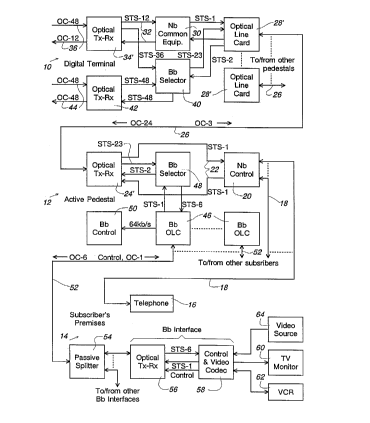
Fig. 2 illustrates an upgraded communications system in
accordance with an embodiment of this invention. In the network of
Fig. 2, the same digital terminal 10, active pedestal 12, and
subscriber's premises 14 exist, but the equipment in each case is
upgraded to accommodate broadband (Bb) as well as narrowband services.
This upgrading is effected in a manner which to a large extent makes
use of the existing equipment as described above and shown in Fig. 1,
so that it can be achieved in a convenient and cost-effective manner.
Referring to Fig. 2, in the digital terminal 10 the optical
transmitter and receiver 34 of Fig. 1 is replaced by an upgraded
optical transmitter and receiver 34' which receives an OC-48 signal
and transmits an OC-12 signal via the existing fibers 36. Similarly,
the optical line cards 28 in Fig. 1 are replaced by upgraded optical
line cards 28' in Fig. 2, which transmit OC-24 signals in the
downstream direction and receive OC-3 signals in the upstream
direction on the existing optical fibers 26, again using WDM. The
narrowband common equipment circuit 30 is retained, and a broadband
selector circuit 40 is added. An additional OC-48 optical transmitter
and receiver 42 can optionally be provided for coupling STS-48 signals
to and from the circuit 40 for additional broadband services (e.g.
video-on-demand services) carried on additional fibers 44, as
~ 35 described further below with reference to Fig. 3.
In the active pedestal 12, the optical transmitter and receiver
24 of Fig. 1 is replaced by an upgraded optical transmitter and
WO 91/09479 2~ 0 ~i 9 ~ 2 7 PCI/CA90/00407
receiver 24' which receives an OC-24 signal and transmits an OC-3
signal via the fiber 26. The narrowband control circuit 20 is
retained with the same connections to the subscriber lines 18. In
addition, the active pedestal 12 is provided with a broadband optical
line card (Bb OLC) 46 for each subscriber 14, a broadband selector
circuit 48, and a broadband control circuit 50. Each Bb OLC 46 is
coupled to a respective optical fiber 52 leading to the respective
subscriber's premises, and serves using WDM to transmit an OC-6 signal
in the downstream direction on this fiber 52 and to receive in the
upstream direction from this fiber 52 a low bit-rate control signal
and, optionally, an OC-1 upstream signal. Each Bb OLC 46 supplies the
control signal, for example having a bit rate of 64kb/s as
illustrated, to the control circuit 50 as described in greater detail
below. As also described further below, for any of the subscribers
the Bb OLC 46 and optical fiber 52 can be replaced by a coaxial cab1e
interface and a coaxial cable to the subscriber's premises, for
communicat;ng electrical rather than optical signals.
In the subscriber's premises 14, the added optical fiber 52 is
coupled via a passive optical splitter 54 to up to 6 broadband
interface circuits, only one of which is shown, each of which
comprises an optical transmitter and receiver 56 and a control and
video decoder and optional coder circuit 58. The circuit 58 receives
an STS-6 signal, corresponding to the downstream OC-6 signal on the
fiber 52, from the optical transmitter and receiver 56 and decodes
this for supply to one or more digital or analog television monitors
60 and video cassette recorders (VCRs) 62, and supplies to the optical
transmitter and receiver 58 the control signal which it produces in
dependence upon, for example, program selections by a subscriber. In
addition, the circuit 58 may receive from an optional video source 64,
or from the VCR 62, a video signal which it encodes and supplies as an
STS-1 signal to the optical transmitter and receiver 56 to constitute
the upstream OC-1 signal on the fiber 52.
In the digital terminal 10, the OC-48 optical signal received
by the optical Tx-Rx 34' comprises, and is divided into, an STS-12
component which is the same as in the prior art arrangement of Fig. 1
and is supplied to the narrowband common equipment 30 in the same
manner, and an STS-36 component which comprises 36 STS-1 channels,
~ W O 91/~9479 2 0 ~ 9 9 ~ 7 PCT/CA90/00401
each for example consisting of an individual digital television
channel. The STS-36 component is supplied to the broadband selector
circuit 40. In a protected form of the equipment, the fibers 36 and
the optical transmitter and receiver 34' are duplicated to provide
active and standby telephony STS-12 signals either of which ;s used by
the narrowband common equipment 30. As the broadband signals do not
generally require similar protection, in this case two sets of STS-36
signals, providing a total of 72 STS-l channels, are supplied to the
broadband selector circuit 40.
As already indicated, the optical transmitter and receiver 42
may also be provided to supply a further 48 STS-l channels to the
broadband selector circuit 40. Two such units can be conveniently
provided, enabling the broadband selector circuit 40 to be supplied in
a downstream direction with a total of 168 STS-l channels.
Each of the optical line cards 28' is supplied with an STS-23
signal, comprising any selected combination of STS-l channels, from
the broadband selector circuit 40, multiplexed (by a multiplexer not
shown in Fig. 2) with the respective STS-l signal which is supplied as
in the prior art from the narrowband common equipment circuit 30. The
optical line card 28' transmits the resulting STS-24 signal downstream
as the OC-24 optical signal on the respective fiber 26.
In the upstream direction, each optical line card 28' receives
a respective OC-3 signal, and from the corresponding STS-3 signal
produces, via a demultiplexer not shown in Fig. 2, the STS-1 signal
for the narrowband common equipment circuit 30 as in the prior art,
and an STS-2 signal containing up to 2 STS-1 upstream channels which
it supplies to the broadband selector circuit 40. These upstream
channels can be switched by the broadband selector circuit 40 either
to one of the optical transmitter and receivers 42 for further
upstream transmission via a fiber 44, or to any of the optical line
cards 28'.
The broadband selector circuit 40 thus can comprise an STS-1
channel selector having, assuming that there are 30 optical line cards
28', 168+30*2=228 STS-l channel inputs and 30 sets of 23 STS-l channel
outputs, with appropriate demultiplexers and multiplexers and
selection control circuitry. The selection control circuitry includes
a memory including information as to which STS-l channels are
W O 91/09479 2 ~ ~ 9 9 2 7 PCT/CAsO/00401 ~
permitted (in accordance with any desired payment scheme, for example)
to be supplied, and are currently supplied, to which subscribers and
hence optical line cards 28'. Such information is updated using the
overhead information in the upstream OC-3 optical signal, in a manner
described in more detail below.
In a similar manner, in the active pedestal 12 the downstream
received OC-24 signal is converted and demultiplexed into the STS-l
telephony signal, which is supplied to the narrowband control circuit
20, and an STS-23 signal which is supplied to the broadband selector
circuit 48. The upstream STS-l telephony signal supplied from the
narrowband control circuit 20 is multiplexed with an upstream STS-2
signal discussed below and supplied to the optical transmitter and
receiver 24', which transmits the corresponding upstream OC-3 optical
signal on the fiber 26.
The broadband selector circuit 48 supplies to each of the Bb
OLCs 46 an STS-6 signal comprising any selected combination of 6 STS-l
channels. This is transmitted downstream on the respective fiber 52
as an OC-6 signal to the respective subscriber. In the upstream
direction, each Bb OLC 46 receives the control signal, which it
supplies to the broadband control circuit 50, and also receives any
upstream OC-l signal which is transmitted on the fiber 52 from the
subscriber's premises, supplying this as an STS-l signal to the
broadband selector circuit 48. As described in greater detail below,
the upstream STS-l signal from any subscriber can also be looped back
by the broadband selector circuit 48 to constitute one of the 6 STS-l
signals which can be supplied downstream on the fiber 52 to the same
subscriber, this being referred to as a local hairpin connection. The
upstream STS-l signals from any two of the subscribers can also be
supplied as the STS-2 signal mentioned above, from the broadband
selector circuit 48 to the optical transmitter and receiver 24', to be
combined with the upstream STS-l telephony signal and transmitted on
the fiber 26 as part of its upstream OC-3 signal.
Although SONET OC-6 and OC-l signals are referred to here as
being carried by the fiber 52, it should be appreciated that the
communications between the active pedestal 12 and each subscriber's
premises 14 may not require full compatibility with the SONET
standard, and accordingly certain parts of this standard (e.g. pointer
~ .
~ W O 9l/09479 2 ~ 6 9 ~ 2 7 PCT/CA90/00401
processing) may be omitted for these optical signals and the
equivalent electrical signals in order to reduce equipment costs.
Furthermore, as described further below, these optical communications
paths may alternatively be replaced by coaxial cable paths.
In the subscriber's premises 14, there may be up to 6
simultaneously active broadband interfaces 56, 58, one in respect of
each of the possible 6 STS-1 channels contained in the downstream OC-6
signal, all supplied with this downstream signal via the passive
optical splitter 54. Within the control and video codec circuit 58 of
each broadband interface, up to two respective STS-1 signals are each
- selected and decoded to form video signals which are supplied to the
television monitor 60 and/or VCR 62. An upstream video signal from
the VCR 62 or video source 64 is conversely encoded into an STS-1
signal and can be transm;tted upstream as the upstream OC-1 signal on
the fiber 52; only one such upstream signal can be transmitted from
any one subscriber's premises at one time.
As the upstream control signal has a low bit rate of for
example 64kb/s, whereas the upstream STS-1 signal has a much higher
bit rate of 51.84Mb/s, these two signals are frequency division
multiplexed for transmission in the upstream direction. The control
signal can be produced in any convenient manner, for example from a
subscriber's selection signals produced by an infra-red television
remote control unit and received by an infra-red receiver which forms
a part of the circuit 58.
Although as described above each video or television channel is
assumed to be digitized in a respective STS-1 signal, this need not be
the case. In particular, for HDTV signals each channel may be
digitized in an STS-3 signal or a group of three STS-1 signals, which
may accordingly be handled collectively by the communications system,
the control and video codec circuit 58 then decoding the respective
three STS-1 signals to recover the HDTV channel. Thus the system can
conveniently accommodate six standard television channels, or three
standard television channels and one HDTV channel, or two HDTV
channels, for each subscriber.
Fig. 3 illustrates in greater detail parts of the digital
terminal 10, showing for simplicity only the downstream direction of
WO 91/09479 2 a ~ ~ ~ 2 ~ PCT/CA90/0040 -
communications; similar and corresponding provisions are made for
handling the upstream control and signal communications.
Referring to Fig. 3, the optical receiver 34' receives in this
case two OC-48 optical signals from the fibers 36, and supplies two
corresponding STS-48 signals to a demultiplexer 65, which supplies two
redundant STS-12 telephony signals to the narrowband common equipment
30, an STS-72 broadcast television channel signal to the broadband
selector 40, and control information derived from the SONET overhead
information OH to a broadband control unit 66. Similarly, two optical
receivers 42 receive OC-48 signals from fibers 44 and produce two STS-
48 signals which are supplied via a demultiplexer 67 to the broadband
selector 40 as an STS-96 signal and as control information, derived
from the SONET overhead information OH, to the broadband control unit
66.
For each optical line card 28' and associated fiber 26, of
which only one is shown in Fig. 3, the digital terminal lO includes a
respective multiplexer 68 which multiplexes the respective telephony -
STS-l signal from the narrowband common equipment 30, an STS-23 signal
from the broadband selector 40, and control information from the
broadband control unit 66 in the SONET overhead OH, to produce the
downstream STS-24 signal which is transmitted by the optical line card
28' on the fiber 26.
By way of example, it is observed that the fibers 44 can carry
either additional broadcast television channels or, more flexibly,
narrowcast as well as or instead of broadcast television channels. By
narrowcast channels is meant channels wh1ch are intended to be
delivered to only one subscriber or to a small group of subscribers.
Examples of such channels include video-on-demand services such as
interactive video services, and individually selected movies whlch may
be played on a central VCR and delivered at a desired time to an
individual requesting subscriber. To facilitate the provision of such
services, it should be appreciated that the fibers 44 can be supplied
with signals from a video or broadband switch (not shown), which is
similarly controlled via the SONET ov;erhead information to provide
desired video or broadband switched connections from service providers
to these fibers.
~69~7
WO 91/09479 PCI /CA90/00401
11
Fig. 4 illustrates the active pedestal 12 in greater detail.
As shown in Fig. 4, the broadband selector circuit comprises a
downstream selector 70 and an upstream selector 72, both of which are
controlled by the broadband control circuit 50. The downstream OC-24
signal on the fiber 26 received by the optical transmitter and
receiver 24' is supplied as an STS-24 signal to a demultiplexer 74~
which supplies a demultiplexed STS-23 payload signal to the downstream
selector 70, the downstream STS-1 telephony signal to the narrowband
control circuit 20, and overhead (OH) information to the control
circuit 50. The downstream selector 70 is also supplied with an STS-8
signal from the upstream selector 72 to provide for hairpin
connections, and an STS-1 idle signal from a generator 76 to insert
into unused signal channels.
The downstream selector 70 has 8 outputs, only 2 of which are
shown in Fig. 4, each for an STS-6 payload signal comprising the 6
STS-1 components or channels selected by the respective one of the 8
subscr;bers. These outputs are coupled to respective multiplexers 78,
which are also supplied with overhead information from the broadband
control circuit 50 and produce STS-6 signals at their outputs. As
shown for the upper subscriber output in Fig. 3, the STS-6 signal is
supplied to an optical transmitter and receiver 80, forming part of
the Bb OLC 46 in Fig. 2, which transmits the corresponding OC-6
optical signal in the downstream direction on the fiber 52. As an
alternative arrangement as shown for the lower subscriber output in
Fig. 4, instead of the optical fiber 52 and associated optical
transmitter and receiver 80, a coaxial cable 82 and coaxial cable
inte=rface B4 can be provided for transmitting and receiving the
electrical signals. Different such arrangements can be provided for
different subscribers. It should be appreciated that in a similar
manner a coaxial cable interface can be provided at other points
between the pedestal and the broadband interfaces in the subscribers'
premises, so that signals are carried partly optically and partly via
coaxial cable, with the optical transmitter and receiver 56 in the
broadband interface being replaced by a coaxial cable interface.
In the upstream direction, for each subscriber the frequency
division multiplexed upstream STS-1 signal and control signal produced
by the optical transmitter and receiver 80 or coaxial cable interface
-
W 0 91/09479 ~ 2 ~ pcT/cAso/
12
84 are separated by a filter 86, which supplies the 64kb/s control
signal to the broadband control circuit 50 and the STS-1 signal to the
upstream selector 72. The 8 STS-1 signals so received by the upstream
selector 72 are supplied as the STS-8 signal to the downstream
selector 70 as already described, and any 2 of them are combined to
form an STS-2 signal which is supplied to a multiplexer 88. The
multiplexer 88 is also supplied with overhead information from the
broadband control circuit 50 and with the upstream STS-1 telephony
signal from the narrowband control circuit 20, and combines these
signals to produce the upstream STS-3 signal which is transmitted as
the OC-3 signal on the fiber 26 by the optical transmitter and
receiver 24'.
The broadband control circuit 50 contains a memory which stores
a provisioning map for each subscriber and each transmission
direction, in accordance with which it controls the downstream
selector 70 and the upstream selector 72. The circuit further
includes a micro-controller and control ROM, in accordance with which
the selectors 70 and 72 are controlled in known manner. The micro-
controller also handles in known manner communications with the
digital terminal 10 via the overhead information OH on the upstream
OC-3 and downstream OC-24 signals, and with the control circuits 58 in
each subscriber's premises 14 via the overhead information OH in the
downstream OC-6 signals and via the 64kb/s control channel in the
upstream direction. In order to handle contention among d;fferent
subscribers, the control channel communications are effected either in
accordance with polling by the broadband control circuit 50 or using
TDMA (time division multiple access) techniques which are known in
themselves.
By way of example, the control channel communications can be a
TDMA scheme in which the 64kb/s channel is subdivided into eight 8kb/s
time channels, the first siX of which are used for 16-byte selection
control messages from the six broadband interfaces of each
subscriber's premises. The seventh such time channel can be used for
hairpin connection requests, in accordance with which the broadband
3~ control circuit 50 controls the downstream selector 70 to supply as
one of the channels in the OC-6 downstream signal the signal contained
in the upstream OC-1 signal of the same subscriber. Thus a video
20~9927
W O 91/09479 PCT/CA90/0040l
13
signal which is available at one of the broadband interfaces in a
subscriber's premises can be distributed to any other broadband
interface in that subscriber's premises, under the subscriber's
control and without involvement of the digital terminal 10. The
eighth such time channel can be used for a handshaking signal on
power-up of any of the broadband interfaces, before it is allocated
one of the first six time channels.
Also by way of example, the provisioning map in the memory of
the broadband control circuit 50 can include a table of downstream
input to output port assignments, storing for each of the 48 STS-1
output channels (an STS-6 signal for each of 8 subscribers) a number
indicating which STS-1 channel incoming to the downstream selector ?~
is assigned to that port. In addition, this map can contain a table
containing the identity of each of the 23 STS-1 video channels
contained in the downstream OC-24 signal on the fiber 26, referred to
as a bearer identity. Furthermore, the provisioning map can contain a
status table for each of the 48 broadband interfaces in the
subscribers' premises, storing in each case the bearer identity for
that interface or an indication that the interface is inactive (i.e.
provisioned but unpowered) or is not provisioned.
The provisioning map in the memory of the broadband control
circuit 50 in the active pedestal 12 is downloaded, and can be
updated, from similar information contained in a map in the broadband
control unit 66 in the digital terminal 10, which in turn is
maintained and updated from an administration center (not shown) and
in accordance with requests from the respective subscribers. As
already indicated, communications to and from these control units are
provided via the 64kb/s upstream control channel from the subscribers'
premises to the active pedestals, and otherwise via the overhead
information OH on the various SONET signal paths. The 64kb/s upstream
control channel is used from each subscr;ber's premises to the
associated active pedestal because the upstream broadband channel is
optional; the overhead information on such an upstream channel could
alternatively be used where this is available.
Communications, such as program channel requests, originated by
a subscriber are conducted via the upstream control channel and via
the active pedestal 12 to the broadband control unit 66 in the digital
2069927
W o 91/09479 PCTtCA90/00401
14
terminal, without any change in the provisioning at the active
pedestal. For example, a subscriber's request for a particular
broadcast television channel available as one of the channels on the
fibers 36 is passed via the upstream control channel to the broadband
control unit 66, which controls the broadband selector circuit 40 to
supply the requested channel to the downstream channel or bearer which
is allocated, in accordance with the stored provisioning maps, to the
subscriber's broadband interface 56, 58 from which the request
originated. As the broadband selector 48 in the active pedestal 12 is
controlled in accordance with the stored provisioning map to couple
the respective bearer channel to the respective subscriber's broadband
interface, no real-time switching takes place within the active
pedestal 12.
The above comments assume that the particular broadband
interface 56, 58 is already active and has a bearer channel allocated
to it. Initially, on powering up the broadband interface, this is not
the case. In this situation the broadband interface communicates via
the eighth TDMA time channel referred to above, indicating that it
requires a bearer channel to be assigned to it. In response to such
an indication, the broadband control unit 66 updates its provisioning
map and that in the broadband control circuit 50 of the active
pedestal 12, allocating a respective bearer for the broadband
interface 56, 58, and assigns to the broadband interface a free one of
the first six TDMA time channels for further communications. In this
manner, contention among different broadband interfaces in a
subscriber's premises is avoided, except on initial power-up of two or
more interfaces simultaneously.
In the event that a broadband interface 56, 58 wishes to be
allocated two video channels simultaneously, for example for viewing
~0 one and recording another, then the broadband interface is allocated
two bearer channels each in the same manner as described above.
For specific program channels, for exampie for the channels
carried by the fibers 44, the broadband control unit 66 in the digltal
terminal may contain further maps, updated by the administration
center or program channel provider, indicating whether or not
individual subscribers are authorized to receive such channels,
storing access codes which are to be supplied by a subscriber to gain
20~927
W O gl/09479 PCT/CA90/00401
access and instigate billing for a program, and so on. Verification
of a subscriber's entitlement to receive a channel is then effected by
the broadband control unit 66 before the broadband selector 40 is
~ controlled to supply the requested channel. It should be appreciated
that, subiect to such verification, the broadband selector 40 is
controlled to supply both broadcast and narrowcast channels to a
subscriber in the same manner.
From the foregoing description it should also be appreciated
that the invention enables existing communications facilities, such as
conventional narrowband active pedestal equipment and telephone
subscriber lines, to be utilized in an upgraded environment which also
provides broadband services, thereby reducing the costs of upgrading.
While optical fiber paths 52 are desirably provided between the active
pedestal 12 and the subscribers' premises, as described above coaxial
cables 82 may be used instead, and to this end already existing
coaxial cables may also be used to further reduce costs.
In addition, because the digital terminal 10 performs the
communications and switching functions in the upgraded arrangement
described above, the arrangement may conveniently be further upgraded
by incorporating the functions of the active pedestal 12 within the
digital terminal, without modification of the subscribers' premises
equipment.
Although a particular embodiment of the invention has been
described in detail above, it should be appreciated that many changes
may be made, in particular in relation to the signal formats used and
the numbers of signal channels on each communication path, active
pedestals per digital terminal, and subscribers per active pedestal.
Numerous other modifications, variations, and adaptations may be made
to the described embodiment without departing from the scope of the
invention as defined in the claims.