Note: Descriptions are shown in the official language in which they were submitted.
~. 207188
~fO 92/03969 PCT/US91/06090
-1-
MULTIPATH LAMINOGRAPHY BYSTEM
Field of the Invention
The invention relates to computerized laminography, and,
in particular, to systems which utilize multi-path
laminography geometries for' high speed, high resolution
inspection.
~ackaround o~ the Invention
l0 Laminography techniques .are widely used to produce cross-
section images of selected planes within objects.
Conventional laminography requires a coordinated motion of any
two of three main components comprising a laminography system
(i.e., a radiation source, an object being inspected, and a
detector). The coordinated motion of the two components can
be in any of a variety of patterns, including linear,
circular, elliptical and random patterns. Regardless of the
pattern of coordinated motion selected, the configuration of
the source, object and detector is such that any point in the
object plane (i.e., the focal plane within the object) is
always projected to the same point in the image plane (i.e.,
the plane of the detector), and any point outside the object
plane is projected to a plurality of points in the image plane
during a cycle of the pattern motion. In this manner, a
cross-section image of the desired plane within the object is
formed on the detector. The images of other planes within the
- object experience movement with respect to the detector thus
creating a blur, i.e. background, on the detector upon which
- is superimposed the sharp cross-section image of the focal
plane within the object. This technique results in sharp
' images of the desired object focal plane. Although any
pattern of coordinated motion can be used, circular patterns
' are generally preferred because they are more easily produced.
The laminography techniques described above are currently
used in a wide range of applications including medical and
industrial X-ray imaging. Laminography is particularly well
suited for inspecting objects which comprise several layers
1
WO 92/03969 2 0 ~ 1 ~ g ~ PCT/US91/06090
-2-
having distinguishable features within each layer. However,
laminography systems which produce such cross-section images
typically experience shortcomings in resolution and/or speed
of inspection, thus accounting for its rare implementation.
These shortcomings are frequently due to the difficulties in
achieving high speed coordinated motion of the source and
detector to a degree of precision sufficient to produce a high
resolution cross-section image.
In a laminography system having a fixed object and a
field of view which is smaller than the object being
inspected, it may be necessary to move the object around
within the field of view thus generating multiple laminographs
which, when pieced together, cover the entire object.
Movement of the object is frequently achieved by supporting
the object on a mechanical handling system, such as an X,Y,Z
positioning table. The table is then moved to bring the
desired portions of the object into the field of view.
Movement in the X and Y directions locates the area to be
examined, while movement in the Z direction moves the object
up and down to select the plane within the object where the
image is to be taken. While this method effectively enables
various areas and planes of the object to be viewed, there are
inherent limitations associated with the speed and accuracy of
such mechanical motions. These constraints effectively act to
increase cycle time, thereby reducing the rates at which
inspection can occur. Furthermore, these mechanical motions
produce vibrations which tend to reduce the system resolution
and accuracy.
Summary of the Invention
The present invention comprises a laminography system
which utilizes multipath scanning geometries which enable
multiple locations on an object to be sequentially viewed
without requiring mechanical movement of the object. Movement
in various scan patterns produces laminographs at desired X,
Y coordinate locations and various Z planes and with different
size FOVs without the need for movement of the viewed object
. ~~ .~VO 92/03969 2 0 7 i 8 8 3 P~.L/US91/06090
-3-
or mechanical movement of the: source.
In accordance with the present invention, a laminography
system is disclosed comprising a source of X-rays, an object
to be viewed, and a detector. The X-ray source includes an
electron gun which emits an electron beam incident upon a flat
target anode. Focus and deflection coils direct the electron
beam, to specific locations on the target to form circular
electron beam patterns on the surface of the target. When the
electrons are slowed down or stopped in the target,
Bremsstrahlung X-rays are generated. Since the electron beam
describes a moving circular pattern on the target, the source
of Bremsstrahlung X-rays also describes a moving circular
pattern coincident with the electron beam pattern. In one
embodiment, steering signals applied to the deflection coils
cause the electron beam spot t,o rotate in a predetermined path
in coordination with a similar path of the detector. In an
alternative embodiment, a digital look-up-table (LUT) sends
digital signals to the deflection coils which cause the beam
spot to follow the circular motion of the electron beam on the
target. In one embodiment which employs the LUT, digital
addresses corresponding to the location of the X-ray detector
along the circle traced by the detector are sent from the
detector to the LUT. The LUT then sends deflection signals
corresponding to specific detector positions to the electron
beam deflection coils. The values of the deflection signals
are calibrated to cause the X-ray source to trace a circular
pattern upon the target which is precisely coordinated with
the motion of the detector.
The source and detector rotate in synchronization about
parallel axes of rotation such that an X-ray image of a
desired region in a selected plane within the object is formed
on the detector. The present invention provides a manner in
which the image region and object plane of the image produced
on the detector can be varied without physically moving the
object. Rather, in one embodiment, an offset signal is
applied to the deflection coils which acts to shift the center
of rotation of the electron beam on the target thus causing a
-4- 2071883 ~'
different region at a different X, Y location of the
object to be imaged upon the detector. In a preferred
embodiment, this offset signal is incorporated with the
deflection signals transmitted from the LUT to the
deflection coils. In one embodiment, the deflection
coils comprise X and Y deflection coils, and the path
traced by the beam spot is circular. Applying a constant
voltage offset to either the X or Y deflection coil
effects a linear shift in the center of the circle traced
by the rotating beam spot, thereby shifting the image
region in the X or Y direction along the selected object
plane within the viewed object. The amplitude of the
constant voltage offsets applied to the coils determines
the direction and amount of the shift in the image region
of the object plane.
In addition, with the present invention, the
location of the image obj ect plane within the obj ect can
be varied in the Z direction, again without movement of
any of the system components. This is achieved by a gain
adjustment which simultaneously changes the amplitudes of
the deflection signals applied to both deflection coils,
thus causing the radius of the scan circle traced by the
beam spot on the target to vary by an amount proportional
to the change in amplitudes of the deflection signals.
Thus, the present invention provides a laminography
system wherein X, Y scanning and Z height scanning is
accomplished with no physica7_ movement of the system
components. Elimination of physical movement
advantageously decreases cycle time of the system while
further eliminating other adverse effects associated with
mechanical movement of the components.
Accordingly, in one aspect. of the present invention,
a laminography system is disclosed comprising:
an X-ray source adapted f:or emitting X-rays from a
moving point, said X-ray source further comprising:
a source of electrons for producing a beam of
electrons;
_5- 2071883
a target anode for converting said beam of
electrons into an X-ray source when said beam of
electrons impinges upon said target anode;
an electromagnetic deflector for electronically
deflecting said beam of electrons onto said target
anode along a first predetermined path about a first
designated location such that X-rays are emitted
from a moving point which follows said first
predetermined path about said first designated
location;
a planar X-ray detector adapted to move along a
predetermined path which is coordinated with said
first predetermined path of said X-ray source to
produce a laminographic image of a first field of
view of an image plane within an object being
inspected; and
a control system for regulating and directing
said electromagnetic deflector to deflect said beam
of electrons onto said target anode along a second
predetermined path about a second designated
location such that X-rays are emitted from a moving
point which follows said second predetermined path
about said second designated location, said second
predetermined path coordinated with said planar X-
ray detector predetermined path to produce a
laminographic image of a second field of view of the
image plane within the object without altering
either the position of the object or said
predetermined path of said X-ray detector.
According to another aspect of the present invention
there is provided a laminography system comprising:
an X-ray source which emits X-rays from a moving
point, said X-ray source further comprising:
a source of electrons for producing a beam of
electrons;
a target anode for converting said beam of
electrons into an X-ray source when said beam of
C
2071883
-6-
electrons impinges upon said target anode;
an electromagnetic deflector for electronically
deflecting said beam of r=_lectrons onto said target
anode along a predetermined first circular path
about a center of rotation, said first circular path
having a first radius;
an X-ray detector coordinated with said X-ray
source so that a first field of view is defined
wherein a first cross-section image of an object
placed in said first fie:Ld of view is produced by
the detector; and
a control system for. regulating and directing
said electromagnetic deflector to deflect said beam
of electrons onto said target anode to cause said
moving point of said X-ray source to rotate in a
second circular path about= said center of rotation,
said second circular path having a second radius, so
that a second field of view is defined wherein a
second cross-section image of said object placed in
said second field of view is produced by the
detector, thereby producing images of said object
from said first and said second fields of view
without altering either the location of said object
or said detector.
According to yet another aspect of the present
invention there is provided a method of producing a
laminographic image comprising the steps of:
generating a source of X-rays which follows a
predetermined path about a designated point, said
generating step further comprising the steps of:
producing a beam of e:Lectrons;
directing said beam c>f electrons into a target
anode thereby producing said X-rays;
electronically deflecting said beam of
electrons to follow said predetermined path about
said designated point;
coordinating an X-ray detector with said moving
-~- 2 0 7 18 8 3
X-ray source so that a f_Leld of view is defined in
an object plane wherein a cross-sectional image of
an object placed in the field of view is produced by
the detector;
maintaining the configurations of said -X-ray
detector and said object; and
electronically shifting the designated point
about which said predetermined path of said beam of
electrons follows, thus shifting the designated
point about which said X-ray source travels, thereby
shifting the location of aaid field of view in said
object plane.
In still yet another aspect of the present invention
there is provided a method of producing a laminographic
image comprising the steps of:
generating a source of X-rays which follows a
predetermined first circular path about a center of
rotation, said first circular path having a first radius,
said generating step further comprising the steps of:
producing a beam of electrons;
directing said beam of electrons into a
target anode thereby ,producing said X-rays;
electronically deflecting said beam of
electrons to follow said predetermined first
circular path about said center of rotation;
coordinating an X-ray detector with said
rotating X-ray source so that a field of view
is defined in an object plane wherein a cross-
sectional image of an object placed in the
field of view is produced by the detector;
maintaining the configuration of said X-
ray detector and said object; and
electronically changing the radius of
rotation of said X-ray source thereby causing
said X-ray source to rotate in a second
circular path about said center of rotation,
said second circular path having a second
20 718 83 .;
_8_
radius, thereby shifting the location of said
field of view.
According to still yet another aspect of the present
invention, a laminography system is disclosed comprising:
a moving source of X-rays, said moving source of X-
rays further comprising:
a source of electrons for broducina a beam of
electrons;
a target anode for converting said beam of
electrons into an X-ray source when said beam of
electrons impinges upon said target anode;
an electromagnetic deflector for electronically
deflecting said beam of electrons onto said target
anode along a predetermined path such that X-rays
are emitted from a movingr point which follows said
predetermined path;
an X-ray detector having an image area which is
coordinated with said moving source of X-rays;
means for supporting an object to be inspected
in a stationary position located between said moving
source of X-rays and said detector; and
a control system comprising:
a driver for driving said moving source of
X-rays along said predetermined path;
a coordinator for coordinating the motion
of said moving source of X-rays with said
detector in a manner which produces a
laminographic image having a field of view in
an object plane of the object under inspection;
and
a field of view shifter for altering said
predetermined path followed by said moving
source of X-rays thereby moving the field of
view and producing a laminographic image of a
different portion of the object without
changing the configuration of either the object
or the detector.
2071883 ~'
-8a-
In yet another aspect of t:he present invention there
is provided a laminography system comprising:
a source of X-rays adapted for emitting X-rays from
a moving point which describes a first circular path
about a center of rotation, said first circular path
having a first radius;
a planar X-ray detector adapted to move along a
predetermined path which i~; coordinated with said
circular path of said X-ra.y source to produce a
laminographic image of a portion of a first image plane
within an object being inspected; and
a control system for causing said X-ray source to
rotate in a second circular path about said center of
rotation, said second circular path having a second
radius, thereby producing a laminographic image of a
portion of a second image plane: within the object without
altering either the position of the object or the path of
the detector.
In accordance with yet another aspect of the present
invention there is provided. a laminography system
comprising:
a source of electrons :Eor nroducina a hPam
electrons;
a deflector for deflecting said beam of electrons;
a target for converting said beam of electrons into
an X-ray source, said target. having a plurality of
concentric rings;
an X-ray detector which is coordinated with said X
ray source to produce a laminographic image of a portion
of an image plane within an obj~=ct to be inspected; and
a control system capable of causing said deflector
to deflect said beam of electrons onto said target so
that a selected circular path,. corresponding to one of
said concentric rings of said target, is traced by said
X-ray source, thereby producing a laminographic image of
a portion of said image plane within the object without
altering the position of the object or the path of the
2071883
-8b-
detector, the position of said image plane being
determined by the selected path of said X-ray source.
In still yet another aspect of the present invention
there is provided a laminography system comprising:
a source of electrons for producing a beam of
electrons;
a deflector for deflecting' said beam of electrons;
a target for converting said beam of electrons into
an X-ray source, said target being formed to have a
cylindrical interior surface;
an X-ray detector which is coordinated with said X-
ray source to produce a laminographic image of a portion
of a f first image plane within an obj ect to be inspected;
and
a control system for causing said deflector to
deflect said beam of electrons onto said cylindrical
interior surface of said target so that a circular path
may be traced at a selected location along the interior
surface of said target, thereby producing a laminographic
image of a portion of an image plane within the object
without altering the position of the object or the path
of the detector, the position of said image plane being
determined by the selected location of said circular path
of said X-ray source.
In yet a further aspect of the present invention
there is provided a laminography system comprising:
a moveable source of penetrating radiation, said
moveable source further comprising:
a source of electron; for producing a beam of
electrons;
a target anode for converting said beam of
electrons into an X-ray source when said beam of
electrons impinges upon said target anode; and
an electromagnetic steering device for
electronically controlling the motion of said
source;
~T
-8c- 2 0 7 18 8 3
an imaging system for producing a cross-
sectional image of a cutting plane of an object,
said imaging system comprising:
a radiation detector having a variable position
image forming region wherein the position of said
image forming region is monitored by a position
sensor which transmits coordinates corresponding to
its position; and
a detector control ~>ystem which receives said
coordinates from said sensor and transmits
corresponding signals to said steering device thus
causing said motion of said radiation source to be
synchronized with said motion of said image forming
region; and
a field of view controller, connected to said
steering device, for se:Lecting first and second
fields of view for said cross-sectional image of a
cutting plane of said object, wherein said first
field of view is produced when said controller
causes said steering devi~~e to move said source of
penetrating radiation along a first predetermined
path having a first reference point and said second
field of view is produced when said controller
causes said steering device to move said source of
penetrating radiation along a second predetermined
path having a second reference point.
In still yet another aspect of the present invention
there is provided a laminography system comprising:
a moveable source of penetrating radiation, said
moveable source further comprising:
a source of electron; for producing a beam of
electrons;
a target anode for converting said beam of
electrons into an X-ray source when said beam of
electrons impinges upon said target anode; and
2071883
-8d-
an electromagnetic steering device for
electronically controlling the motion of said source
along a predetermined path;
an imaging system, coordinated with said
moveable source of penetrating radiation, for
producing a cross-sectional image of a cutting plane
of an object located adjacent said moveable source
and said imaging system such that radiation from
said source passes through said object before
reaching said imaging system; and
a field of view controller for producing first
and second fields of view of said cross-sectional
image of a cutting plane of said object solely by
controlling the configuration of said source
predetermined path.
In still yet another aspect of the present invention
there is provided a laminography system comprising:
a source of X-rays which travels along a
predetermined first circular path about a center of
rotation, said first circular p;~th having a first radius;
an X-ray detector coordinated with said X-ray source
so that a field of view is defined in an object plane
wherein a cross-section image of an obj ect placed in the
field of view is produced by the detector; and
a control system for cau;~ing said X-ray source to
rotate in a second circular path about said center of
rotation, said second circular path having a second
radius, thereby shifting the 7_ocation of said field of
view, wherein said control system comprises a look-up
table (LUT).
In still yet another aspect of the present invention
there is provided a laminograph;r system comprising:
a source of X-rays adapted for emitting X-rays from
a moving point, said source of X-rays further comprising:
a source of electron; for producing a beam of
electrons;
2071883
-8e-
a target anode for converting said beam of
electrons into an X-ray source when said beam of
electrons impinges upon said target anode;
an electromagnetic deflector for electrically
deflecting said beam of electrons onto said target
anode along a first circular path about a center of
rotation, said first circular path having a first
radius;
an X-ray detector having an image area which is
adapted to move along a predetermined path which is
coordinated with said first circular path of said X
ray source to produce a laminographic image of a
portion of a first image plane within an object
being inspected; and
a control system for' regulating and directing
said electromagnetic deflector to deflect said beam
of electrons onto said target anode to rotate said
X-ray source in a second circular path about said
center of rotation, said second circular path having
a second radius, thereby producing a laminographic
image of a portion of a second image plane within
the object without altering either the position of
the object or the path of i~he detector image area.
In still yet another aspect of the present invention
there is provided a laminography system comprising:
a moving source of X-rays, said moving source of X-
rays further comprising:
a source of electron; for nrnc3l»-i na a haam of
electrons;
an electromagnetic deflector for electronically
deflecting said beam of electrons;
a target anode for converting said beam of
electrons into an X-ray aource when said beam of
electrons impinges upon said target anode, said
target anode having a plurality of concentric rings
wherein said deflector deflects said electron beam
to a specific concentric ring;
2071883
-8f-
an X-ray detector which is coordinated with
said moving source of X-rays to produce a
laminographic image of a first portion of an image
plane within an object t.o be inspected when said
moving source of X-rays is from a first one of said
concentric rings; and
a control system fox- deflecting said beam of
electrons onto said target: anode so that a selected
circular path, corresponding to a second one of said
concentric rings of said target anode, is traced by
said moving source of X-:rays, thereby producing a
laminographic image of a second portion of said
image plane within the object without altering the
position of the object or the configuration of the
detector, the change in position of said image plane
from said first portion to said second portion being
determined by the selection of said first and second
concentric rings of said X-ray target anode,
respectively.
In still yet another aspecvt of the present invention
there is provided a laminography system comprising:
a moving source of X-rays, said moving source of X-
rays further comprising:
a source of electrons for producing a beam
of electrons;
an electromagnetic deflector for
electronically deflecting said beam of
electrons;
a target anode for converting said beam of
electrons into an X-ray source when said beam
of electrons impinges upon said target anode,
said target anode being formed to have a
cylindrical interior surface about a central
axis;
2071883
_8g_
an X-ray detector which is coordinated
with said moving source of X-rays to produce a
laminographic image of a portion of a first
image plane within an object to be inspected
when said deflector deflects said electron beam
to a first location along said central axis;
and
a control system for deflecting said beam
of electrons onto a second location along said
central axis of said cylindrical interior
surface of said target anode, thereby producing
a laminographic image of a portion of a second
image plane within t:he object without altering
the position of the object or the configuration
of the detector, the change in position of said
laminographic image from said first image plane
to said second image plane being determined by
the selection of said first and second
locations along said central axis of said
circular path of said moving source of X-rays.
Brief Description c>f the Drawings
An embodiment of the pre~:ent invention will now be
described by way of example only with reference to the
accompanying drawings in which:
Figures 1 and 2 are schematic views of a
laminography system in accordance with the present
invention;
Figures 3a and 3b illustrate the manner in which a
laminographic system in accordance with the present
invention is utilized to produce an X-Y axis shift of the
image region within the object;
Figures 4a and 4b illustrate the manner in which a
laminographic system in accordance with the present
invention is utilized to produce a Z-axis shift of the
3 5 imaged region of the obj ect plane within the obj ect ; and
2071883
-8h-
Figures 5a, 5b and 6 illu;~trate possible embodiments
of a target that may be used in accordance with the
present invention.
Detailed Description of the Invention
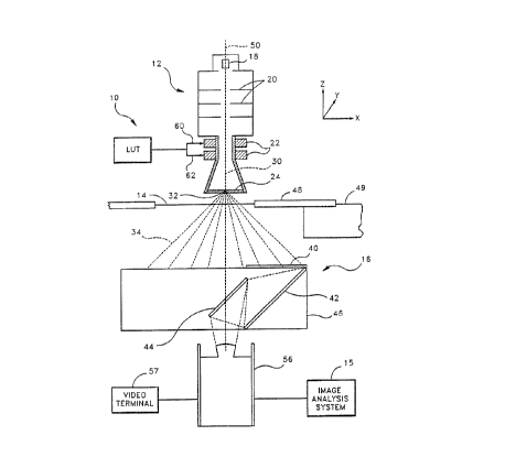
Figure 1 illustrates a schematic diagram of a
laminography system 10 in ac~~ordance with the present
invention. The system 10 comprises a source of X-rays 12
positioned above an object 14 to be viewed, and a
rotating X-ray det4ector 16, positioned below the object
14, opposite the X-ray source 7_2. The object 14 may, for
example, be an electronic item such as a circuit board, a
manufactured item such as an aircraft part, a portion of
a human body, etc.
The invention acquires X, Y plane cross-sectional
images of the object 14 under inspection using multipath
laminography
1
,a ~,O 92/03969 _ . ~ ~ ~ ~ ~ ~ ~ p~/US91/06090
-g-
geometries which enables multiple locations of the object 14
to be sequentially viewed without requiring mechanical
movement of the object 14. Movement in various scan circles
produces laminographs at the desired X~ Y coordinate locations
and various Z planes without the need for movement of the
viewed object 14. In one embodiment, the invention may be
interfaced with an analysis system 15 which automatically
evaluates the cross-section image generated by the system l0
and provides a report to the user that indicates the results
of the evaluation.
The source 12 is positioned adjacent the object 14, and
comprises an electron gun 18, a set of electrodes for bearing
acceleration and focus 20, a focus coil 60, and a steering
yoke or deflection coil 62, and a substantially flat target
anode 24. An electron beam :30 emitted from the electron gun
18 is incident upon the target 24, producing an X-ray spot 32
which serves as an approximately point source of X-rays 34.
The X-rays 34 originate in the target 24 from the point where
the electron beam 30 impinges upon the target 24 and, as
described below, illuminate various regions of the object 14.
The object 14 is typically mounted on a platform 48 which
may be affixed to a granite table 49, so as to provide a
rigid, vibration-free platform for structurally integrating
the functional elements of the system 10, including the X-ray
source 12 and turntable 46. It is also possible that the
platform 48 comprises a positioning table that is capable of
' moving the object 14 relatively large distances along three
mutually perpendicular axes X, Y, and Z.
The rotating X-ray detector 16 comprises a fluorescent
screen 40, a first mirror 42, a second mirror 44, and a
turntable 46. The turntable 46 is positioned adjacent to the
object 14, on the side opposite to the X-ray source 12. A
camera 56 is positioned opposite the mirror 44, for viewing
images reflected into the mirrors 42, 44 from the fluorescent
screen 40. The camera 56 typically comprises a low light
level closed circuit television camera that produces a video
image of the X-ray image fonaed on the fluorescent screen 40.
t
WO 92/03969 ~ ~ ~'~ ~ ~ ~ PCT/US91/06090
-10-
The camera 56 may, for example, be connected to a video
terminal 57 so that an operator may observe the image ,
appearing on the detector 40. The camera 56 may also be
connected to the image analysis system 15.
The laminography system l0 is advantageously encased by
a supporting chassis (not shown) which acts to prevent
undesired emissions of X-rays, ~~ well as facilitating the
structural integration of the maj elements of the system 10.
In operation, X-rays 34 prod :ed by the X-ray source 12
illuminate and penetrate regions .~f the object 14 and are
intercepted by the screen 40. Synchronous rotation of the X
ray source 12 and detector 16 about an axis 50 causes an X-ray
image of a plane 52 (see Figure 2) within the object 14 to be
formed on the detector 16. Although the axis of rotation 50
illustrated is the common axis of rotation for both the source
12 and detector 16, one skilled in the art will recognize that
it is not necessary for the axes of rotation to be collinear.
In practice, it is sufficient that the axes of rotation be
parallel. X-rays 34 which penetrate the object 14 and strike
the screen 40 are converted into visible light reflected by
the mirrors 42, 44 and into the camera 56.
Referring to Figure 2, the electron beam 30 is emitted
from the electron gun 18 and travels in a region between the
electrodes 20 and steering coils 22. The electrodes 20 and
coils 22 produce electromagnetic fields which interact with
the electron beam 30 to focus and direct the beam 30 onto the
target 24 forming an electron beam spot 32 from which X-rays
are emitted. Preferably, the size of the electron beam spot
32 on the target is on the order of .02 to 10 microns in
diameter. The steering coils 22 enable the X-ray source 12 to
provide X-rays 34 from the X-ray spots 32 wherein the location
of the spots 32 move in a desired pattern around the target
24.
Preferably, the steering coils 22 comprise separate X and
Y electromagnetic deflection coils 60, 62 which deflect the
electron beam 30 discharged from the electron gun 18 in the X
and Y directions, respectively. Electrical current flowing in
..._
~'O 92/03969 PCT/US91/06090
-11-
the steering yoke 62 creates a magnetic field which interacts
with the electron beam 30 causing the beam 30 to be deflected.
However, one skilled in the art will also recognize that
electrostatic deflection techniques.could also be used to
deflect the electron beam 30. Preferably, an LUT 63
outputs voltage signals which, when applied to the X and Y
deflection coils 60, 62 cause the electron beam spot 32 to
rotate, thus producing a circular pattern on the surface of
the target 24. In one embodiment, the LUT 63 provides the
output voltages in response to addressing signals from a
master computer (not shown) which may be included within the
image analysis system 15. The output voltages are
advantageously predetermined using a calibration technique
which correlates the position of the turntable 46, and the
position of the X-ray beam spot 32.
The present invention provides a method and apparatus for
processing laminographic images of various regions of the
object 14 which requires little or no physical movement of the
object 14 or the supporting table 48. In accordance with the
present invention, desired regions of the object are brought
within the field of view of t:he system by moving the location
of the field. This is accomplished by moving the location of
the pattern traced by the X-ray beam spot 32 on the target 24.
In this manner, various portions of the object 14 are brought
within the field of view and images are produced of that
portion of the object coinciding with the field of view. In
accordance with the present invention, the voltages applied to
the X and Y deflection coils 60, 62 are varied in order to
produce rotating X-ray beam paths of distinct radii having
distinct x, y locations on the target 24.
Figure 3a illustrates the laminography geometry and
technique used to image different x,y regions of the object by
electronically moving the center of rotation of the rotating
X-ray source on the X-ray source target. The rotating spot 32
of X-rays 34 formed in the manner described above is
positioned above the object 14 to be viewed. For purposes of
illustrating the operation of the invention, the object 14
z~~~~s~
WO 92/03969 PCT/US91/06090
-12-
contains the patterns, of an arrow 70 and a cross 72 located
within different regions of an internal plane 74 of the ,
object. As previously described, signals from the LUT 63 can
be applied to the X and Y deflection.coils 60, 62 (Figure 2) ,
so as to cause the X-ray spot 32 to trace a circular path on
the target 24. In the position labelled A (Figure 3a) , a scan
circle 80 having a center C1 is produced which emits X-rays 34
incident upon the object 14. As the X-ray spot 32 and
detector 16 rotate in synchronization as described above, the
X-rays 34 are emitted in diverging beams at each point along
the scan circle 80, forming a family of cones or conical
regions wherein each cone has an apex defined by the X-ray
spot 32 and a base defined by the detector assembly 16. Two
cones 82, 84 defined by the X-ray spot 32 and detector 16 at
two different locations along the circular path of the scan
circle 80 are shown. The intersection of the conical regions
around a complete rotation of the X-ray spot 32 and detector
16 defines a set of points which comprise the field of view.
Thus, the portion of the object plane which coincides with the
field of view is imaged by the detector 16. As illustrated,
the intersection of the cones 82, 84 produced by the rotating
X-ray spot 32 and detector 16 is substantially centered about
the arrow pattern 70 in the internal plane 74. Thus, the
region imaged when the X-ray source 32 traces the scan path 80
includes the arrow pattern 70, and the object, or focal plane
is the internal plane 74. In this manner, the rotating X-ray
spot 32 and detector 16 produce a distinct image 90 of the
arrow upon the detector 16.
Because the cross pattern 72 lies outside the field of
view defined by the intersecting cones 82 and 84 when the path
80 is tra:_~d by the electron beam 30, the image of Lhe cross
pattern 72 does not fall on the detector 16 at any time during
the rotation of the detector 16 and thus, does not form an
image on the detector 16.
Application of an offset voltage to the X and/or Y
deflection coils 60 and/or 62 acts to shift the path traced by
the X-ray source 32, as shown in Figure 3b, such that a scan
_ u_.. _. ,
~~ WO 92/03969 PCT/US91/06090
-13-
circle 100 having a center C2 is traced by the X-ray spot 32
. on the target 24. As the X-ray spot 32 rotates about the
circle 100, a second family of cones, illustrated by the two
cones 102, 104, intersects the object,plane 74 and defines a
field of view substantially centered about the cross pattern
72. Thus, a new field of view, which is linearly displaced
from, the original field of view shown in Figure 3a, is defined
when the path traced by the X-ray source 32 has its center of
rotation shifted in the X and/or Y directions from center of
rotation C1 to center of rotation C2.
The arrow pattern 70 now lies outside the field of view
in the object plane 74 such that, as the X-ray spot 32 and
detector 16 rotate, a cross-sectional image of the cross
pattern 72 is produced on the detector 16, and the image of
the arrow 70 does not appear . The amplitude of the offset
applied to the deflection coils 60, 62 is proportional to the
distance and direction the path traced by the X-ray spot 32 is
shifted, i.e., the distance and direction that the center of
the scan circle is shifted.. Thus, the laminography geometry
of the present invention enables different regions of the
obj ect 14 to be viewed and imaged upon the detector 16 without
any physical movement of ttie source 12, object 14, or detector
16. Furthermore, any vibrations or other adverse effects
resulting from mechanical movement of the system components
are eliminated, thereby increasing the speed and accuracy of
the system 10.
It should be noted that shifting the position of the path
traced by the X-ray source 32 results in a change in the
distance of the path followed by the electron beam 30 (figures
. 30 1 and 2). That is, the distance from the cathode filament to
the target surface changes each time a shift is effected in
. the position of the X-ray spot 32 (which coincides with the
electron spot on the target 24). This results in a change in
the focal length of the electron beam 30, so that dynamic
focusing of the beam must be brought about in order to
maintain a sharp focal point of the electrons within the beam
30 at the surface of the target 24. Thus, the present
207~88_~3 ;
WO 92/03969 PCT/US91/06090
-14-
invention advantageously effects a change in voltage applied
to the focusing coil that is appropriate to maintain the focal
point of the beam 30 at the surface of the target 24.
Referring to Figure 4a and Figure 4b, the present
invention further provides a laminography system having a
geometry which can be utilized to effect a shift or change in
the object plane 74. Figure 4a illustrates an object 14
having the patterns of an arrow 70 and a cross 72 located
therein. The cross pattern 72 is located in a first plane 110
and the arrow pattern 70 is located in a second plane 112,
wherein the first plane 110 lies above and is parallel to the
second plane 112. The X-ray beam spot 32 traces a scan circle
114 having a radius R1, defining a family of cones including
cones 116, 118. The intersection of the cones around the
circle 114, including cones 116, 118, forms an image region
substantially centered about the cross pattern 72, such that
the first plane 110 is defined as the object plane 74. As the
X-ray spot 32 and detector 16 rotate in synchronization, a
distinct image 120 of the Cross pattern 72 is produced on the
surface of the detector 16. The image of the arrow 70, which
lies in the second plane 112 and is outside the object plane
74 defined by the cones 716, 118, is not stationary on the
detector 16 during the entire rotation of the detector 16 and
thus, appears blurred.
Figure 4b illustrates that by equally adjusting the gain
of the voltages output from the LUT 63 to both deflection
coils 60, 62, thereby changing the amplitude of the sine and
cosine signals, the radius of the scan circle traced by the X-
ray spot 32 can be varied to produce images of regions within
distinct planes in the object 14. With the adjustment ~f the
gain applied to the output from the LUT 63, the scan circle
114 is increased in radius by-a value nR to a radius R2,
thereby forming a scan circle 124 defining a second family of
cones including the cones 126, 128. Because of the larger
radius R2 of the second scan circle 124, the set of points
defined by the intersection of the second family of cones,
~Q~I8~3
WO 92/03969 PCT/US91/06090
-15-
including cones 126, 128, is displaced in the negative Z
direction relative to the region imaged when the X-ray source
32 follows the path 114 (Figure 4a). Thus, the object plane
74 is lowered by an amount nZ to the second plane 112, and the
image region is substantially centered about the arrow pattern
70. As the X-ray spot 32 and detector 16 rotate, a distinct
image 130 of the arrow pattern 70 is then produced on the
detector 16, while the image of the cross pattern 72, lying
outside the object plane 74, appears blurred. The amplitude
of the gain adjustment made to the voltages applied to the
deflection coils 60, 62 is proportional to the direction and
amount of the shift oZ in the object plane 74. For example,
a large increase in the gain would result in a relatively
large movement of the image plane 74 in the downward (i.e.,
negative Z) direction, while a small decrease in the gain
would result in a relatively small movement of the image plane
74 in the upward (i.e., positive Z) direction. In this
manner, the geometry utilized in the laminographic system of
the present invention further allows various planes in the
object 14 to be imaged upon the detector 16 without mechanical
movement of any of the system components.
It will be understood that different configurations of
the target 24 may be used in accordance with the present
invention. For example, Figures 5a, 5b and 6 illustrate two
possible embodiments of a target that may be used in
accordance with the present invention. In Figures 5a and 5b,
a cross-sectional view of an alternative target 200 is shown.
_ The target 200 is constructed as a hollow cylinder which has
a coating of tungsten, or similar material, on its inner
surface. As shown in Figure :5a, when the electron beam 30 is
deflected in a circular pattern so that it strikes the
interior surface of the target 200, X-rays 210, which are
incident upon the detector, are emitted from the spots where
the electron beam 30 strikes the target 200 so that the X-rays
intersect in the focal plane '74. When the path traced by the
electron beam 30 is moved vertically up to another portion of
2~71~~3
WO 92/03969 PCT/US91/06090
-16-
the interior of the target 200, as shown in Figure 5b, the
X-rays 210 are emitted so that they intersect in another focal
plane 74 that is vertically displaced in the positive Z
direction from the focal plane defined by the X-rays shown in
Figure 5a. Thus, distinct focal planes can be defined along
the Z axis using the configuration of the target 200 shown in
Figures 5a and 5b.
Figure 6 shows .a cross-sectional view of another
embodiment of the target. In the embodiment shown in Figure
6, a target 250 comprises multiple concentric rings which are
formed so that X-rays 260 are produced when the electron beam
30 is incident upon the surface of the target 250. Each of
the rings has a different radius so that objects in different
focal planes along the Z axis are imaged when the electron
beam 30 is deflected to trace a path on selected ones of the
rings of the target 250.
The invention may be embodied in other specific forms
without departing from its spirit or essential
characteristics. The described embodiments are to be
considered in all respects only as illustrative and not
restrictive. The scope of the invention is, therefore,
indicated by the appended claims rather than by the foregoing
description. All changes which come within the meaning and
range of equivalency of the claims are to be embraced within
their scope.