Note: Descriptions are shown in the official language in which they were submitted.
WO91/15061 2~ PCT/US91/00519
A ~ETHOD FOR SYNC~RONTZING THE
TRANSMISSIONS IN A SIMULCAST TRANSMISSION SYSTEM
R~C~GROUND OF THE lNV~N-~ ION
FIFT~ OF T~F. INV~TION:
The disclosed invention generally relates to the field
of simulcast transmission systems, and more particularly a
method and apparatus for automatically synchronizing the
transmissions in a wide area simulcast transmission system.
DF.SCRIPTION OF T~TF`. PRIOR A~T:
A number of methods have been proposed or are in use
l~ today for automatically synchronizing the message
transmissions of transmitters utilized in simulcast
transmission systems. One such system is described in U.S.
Patent No. 4,718,l09 to Breeden et al., entitled "Automatic
Synchronization System" which is assigned to the Assignee
of the present invention. A simulcast transmitter system
is described wherein a master transmitter was centrally
located within a plurality of secondary transmitters
disposed in an annular fashion around the central
transmitter. The innermost annular ring of transmitters
was synchronized to the master transmitter, while the
remainder of the system transmitters were disabled. The
next adjacent annular band of transmitters was then
synchronized to the innermost annular band and the process
was repeated until every annular band in the system was
synchronized. Such a synchronizing arrangement guaranteed
adjacent annular bands were properly synchronized, however
such a system did not necessarily provide for variations in
delay which were introduced do to not utilizing a common
signal source for making the delay measurements.
An alternate method of synchronizing the transmitters
in a simulcast transmission system having a large number of
transmitters is shown in Figure l. An important factor in
determining the regularity to which the transmissions in
-
WO91/15061 2~ PCT/US91/00519
such a simulcast transmission system was synchronized was
the time required to complete the transmitter propagation
delay measurement sequence. For a large simulcast
transmission system, such as one having forty transmitters,
delay measurement times of forty seconds and more were
typical when each region was sequentially accessed for
measuring the individual transmitter propagation delays.
Figure 1 shows a typical large multi-transmitter simulcast
system 100 which has been divided into a plurality of
smaller transmission regions 102, each transmission region
102 having a plurality of regional transmitters 104
responsive to a regional controller 106 for controlling the
transmission of messages and further for controlling the
transmission of information utilized for synchronization of
the transmitter transmissions. Each transmission region
102 included one or more regional receivers 108 (only one
of which is shown), which was coupled to the corresponding
regional controller to provide monitoring of delay
measurement signals required to enable the measurement of
the inter-regional propagation delays for each of the
regional transmitters in each transmission region 102. By
splitting the simulcast transmitter system 100 into the
smaller transmission regions 102, the inter-regional
propagation delay measurements could be simultaneously
measured for regional transmitters in alternate
transmission regions, such as shown for regional
transmitters 104 and 104" within transmission regions 102
and 102", respectively, thereby reducing the total time
required to synchronize transmissions within the system.
Measurement of the transmitter propagation delays as shown
in Figure 1, while speeding up the inter-regional
propagation delay measurement process, presented a new set
of problems, such as that of measuring the intra-regional
propagation delays required to synchronize the transmitters
in adjacent transmission regions.
In order to measure these intra-regional propagation
delays, an output 110 of one of the regional controllers
106 was redirected to a regional transmitter 104 in an
~'O91/15061 ~ PCT/US91/00519
3
adjacent transmission region, as shown in Figure 1, in
order to establish a signal source for the intra-regional
measurements. Once the intra-regional transmission
propagation delays were measured, the intra-regional
differential propagation delays were computed and then
added to the inter-regional differential propagation delays
for each transmission region to determine the total
transmission delay required for each transmitter to
synchronize the transmissions of the transmitters within
each transmission region and between transmission regions.
A number of problems arose from the method of Figure 1
for synchronizing the transmissions of such a simulcast
transmitter transmission system. The intra-regional
transmission propagation delays required a means for
switching between two transmission sources for the same
transmitter, i.e. controller 106 and controller 106'.
This switching of sources added errors to the measurements
consisting of delays introduced by the added signal path
utilized to make the intra-regional measurements, which
could easily approach hundreds of microseconds of added
delay. When multiply adjacent transmissions regions
occurred, i.e. where more than two transmission regions
overlaped, additional switching hardware was required to
interconnect each of the regions for measurement, further
contributing to errors in the propagation delay
measurements, and adding substantially to the cost of the
system. The method of Figure 1 also restricted cross check
measurements between the adjacent regions without the
utilization of additional hardware to provide such cross
check measurements. The method of Figure 1, also became
inoperative in those instances when the transmitter used to
compare intra-regional measurements became inoperative. To
resolve this problem required additional hardware in the
form of redundant switching to other transmitters within
the transmission regions to be available when the primary
transmitter failed. The method of Figure 1 also precluded
restructuring of the transmitters in the system as the
system operator deemed appropriate, such as when a better
WO91/15061 PCT/US91/00519
4 ~
combination of transmitters was determined to provide for
more accurate propagation delay measurements within the
simulcast transmitter system.
SU~M~Y OF T~ NV~ ION
It is an object of the present invention to provide a
method for synchronizing the transmissions of a simulcast
transmitter transmission system.
It is a further object of the present invention to
provide a method for synchronizing the transmissions of the
simulcast transmitter transmission system which provides
improved measurement capability.
It is a further object of the present invention to
provide a method for synchronizing the transmissions of the
simulcast transmitter transmission system which provides
measurement reconfigurability.
It is a further object of the present invention to
provide a method for synchronizing the transmissions of the
simulcast transmitter transmission system which provides
simple cross-check measurement capability.
These and other objects of the present invention are
achieved by providing a method for synchronizing message
transmissions in a simulcast transmitter system. The
system comprises at least two transmission regions, each
transmission region having at least one regional receiver
coupled to a regional controller for receiving delay
measurement signals generated for the measurement of
transmission propagation delays. Each transmission region
includes a plurality of regional transmitters having
adjustable transmission delays which are responsive to the
regional controllers for transmitting the messages and the
delay measurement signals. A master controller couples to
each regional controller for enabling the message
transmissions and for initiating the transmission of delay
measurement signals for the measurement of propagation
delays. The master controller generates a first delay
measurement signal for the first region, and effects the
WO91/15061 PCT/US91/00519
~ 4
transmission of the first delay measurement signal from a
selected one of the plurality of regional transmitters
operating within the first transmission region. The
regional controller within the first region measures the
propagation delay from the selected transmitter within the
first transmission region. The master controller next
generates a second delay measurement signal and effects the
transmission of the second delay measurement signal from a
selected one of the plurality of regional transmitters
operating within a second transmission region adjacent to
the first transmission region. The regional controller
within the first region measures the propagation delay from
the selected transmitter within the second transmission
region. The intra-regional differential propagation delay
between the transmission of the first and second delay
measurement signals is computed. The transmission delays
for each regional transmitter operating within the first
and second transmission regions are computed based on the
computed intra-regional differential propagation delay, and
the transmission delays for each transmitter within the
first and second transmission regions are adjusted to
equalize the intra-regional differential transmission
delays between each transmission region.
RRT~F n~.SC~TpTTON OF T~ n~TNGS
The features of the invention which are believed to be
novel are set forth with particularity in the appended
claims. The invention itself, together with its further
objects and advantages thereof, may be best understood by
reference to the following description when taken in
conjunction with the accompanying drawings, in the several
figures of which like reference numerals identify identical
elements, in which, and wherein:
Figure 1 is an electrical block diagram showing the
implementation of the inter-regional and intra-regional
WO91/15061 ~ 4 PCT/US91/00519
delay measurements in a prior art simulcast transmission
system.
Figure 2 is an electrical block diagram showing the
implementation of the inter-regional and intra-regional
delay measurements in the simulcast transmission system of
the present invention.
Figures 3A and 3B are signal flow diagrams
illustrating the inter-regional delay measurement procedure
and the intra-regional delay measurement procedure,
respectively, for the simulcast transmission system of the
present invention.
Figure 3C is a diagram illustrating one embodiment of
an intra-regional differential propagation delay
measurement sequence utilized in the simulcast transmission
system of the present invention.
Figure 4 is an electrical block diagram showing a
first embodiment for the implementation of the regional
controllers utilized in the simulcast transmission system
of the present invention.
Figure 5A is a signal waveform showing the delay
measurement utilized in the simulcast transmission system
of the present invention.
Figure 5B is an electrical block diagram showing the
stop detector utilized in the first embodiment of the
simulcast transmission system of the present invention.
Figure 6 is an electrical block diagram showing the
transmitter utilized in the first embodiment of the
simulcast transmission system of the present invention.
Figures 7A-7C are flow charts showing the procedures
for equalizing the propagation delays of the simulcast
transmission system of the present invention.
Figure 8 is an electrical block diagram showing a
second embodiment for the implementation of the regional
controllers utilized in the simulcast transmission system
of the present invention.
Figure 9 is an electrical block diagram showing a
second embodiment for the implementation of the regional
WO91/1~061 PCT/US91/00519
7 ~ $6~
transmitters utilized in the simulcast transmission system
of the present invention.
DR~ C~TPTTON OF T}7P'. P~P~FF.~2R~n P~ RODTM~NT
Figures 2-9 show the preferred embodiment of the
present invention, a simulcast transmission system
providing improved propagation delay measurement capability
which is required for the synchronization of message
transmissions from a plurallty of transmitters operating in
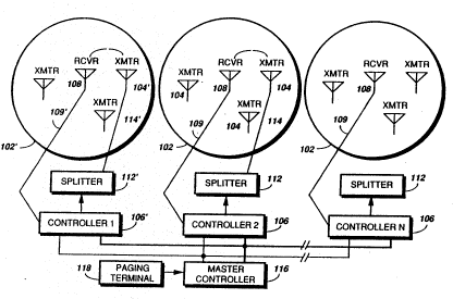
a plurality of transmission regions. As shown in Figure 2,
the simulcast transmitter system of the present invention
comprises at least two transmission regions 102. Figure 2
in particular shows three regions, although it will be
appreciated from the description to follow, any number of
regions may be accommodated by the system. Each
transmission region includes at least one regional receiver
108 for receiving transmitted delay measurement signals.
The regional receivers, such as conventional FM (frequency
modulated) receivers, are well known in the art. Each
regional receiver 108 is coupled to a regional controller
106 through any of a number of well known communication
links lO9, such as wireline links, RF links employing link
transmitters and receivers, and microwave links. It will
be appreciated, the number of regional receivers required
within each transmission region is a function of such
parameters as the size and topography of the transmission
region. Transmission regions covering large cities, as for
example the New York Metropolitan area, would generally
require multiple regional receivers due to the enhanced
propagation delays encountered between the transmitters and
receivers within such large cities. When multiple
35 receivers are required in the simulcast transmission
system, it will be appreciated a signal strength voting
means (not illustrated), which is well known in the art, is
utilized to select the regional receiver which provided the
WO91/15061 ~ PCT/US91/00519
, - ` 8
greatest signal output for propagation delay measurements
from each transmitter within the transmission region. It
will also be appreciated, cross delay measurements, i.e.
the comparison of the propagation delay measurement between
each of the regional receivers, is required to account for
differences in the signal paths between each of the
plurality of receivers and the regional controller.
Each transmission region includes a plurality of
regional transmitters 104 which are responsive to the
regional controllers 106 for transmitting the messages, and
for transmitting the delay measurement signals, as shown in
Figure 5, and which will be described in detail below.
Returning to Figure 2, each regional controller 106 may
couple to a splitter 112, or point-to-multipoint
transmission device when more than one transmitter is
provided within a region. Splitters, providing such point
to multipoint transmission are well known in the art.
The regional controller is to be described in detail with
Figure 3 below.
The simulcast transmission system of the present
invention also includes a master controller 116, unlike
that of the prior art systems, which couples to each
regional controller, for enabling the distribution of the
message transmissions, and for initiating the transmissions
of the delay measurement signals which are utilized for the
measurement of the inter-regional and intra-regional
propagation delays, as will be explained below. A paging
terminal 118 couples to the master controller 116 to
provide the messages which are inputted into the system by
the message originators over the public switched telephone
network (PSTN), which is not shown. The operation of
paging terminals such as shown in Fig. 2 are well known in
the art.
The method of measuring the propagation delays within
the simulcast transmitter system of the present invention
is further best understood by way of the signal flow
diagrams of Figures 3A and 3B. The values of ultimate
interest are the differences in the transmission, or
Wl~91/15061 PCT/US91/00519
propagation delays between transmitters. The differential
propagation delays are calculated from the measured
propagation delays in two stages, the inter-regional
differential propagation delay measurements and
calculations which are illustrated with Figure 3A, and the
intra-regional differential propagation delay measurements
and calculations, which are illustrated with Figure 3B.
The inter-regional and intra-regional propagation delay
measurements are initiated at predetermined times, such as
once each day, although it will be appreciated other
measurement intervals, such as twice each day or every
other day, can be utilized as well depending upon the
stability of the transmission delays of the overall
simulcast transmission system. The following nomenclature
is used to identify the system elements to allow
computation of the differential propagation delays from the
corresponding propagation delay measurements:
Cn, Ck - regional controller in nth and kth region
Xmn, Xmk - transmitter m in nth and kth region
Rjn, Rjk - Receiver j in nth and kth region
M - Master Controller
The propagation delays within the system are
identified using the following notation:
T(source)(destination)
where T is the propagation delay time for a signal, in
3t) this instance the delay measurement signal, to propagate
from the signal source to the signal destination. As an
example, the notation TCnXln identifies the transmission
time, or propagation delay, encountered between the
regional controller in transmission region n and
transmitter 1 in transmission region n.
Figure 3A is a signal flow diagram for the inter-
regional propagation delay measurements. Each measurement
is initiated by the master controller which generates a
WO91/15061 PCT/US91/00519
measurement control signal which is suitably encoded to
select the regional controller for the region in which the
measurements are to be made, and which identifies the
measurement initiated as an inter-regional propagation
delay measurement. The regional controller so selected
then sequences through each of the transmitters in a
predetermined order to make the individual propagation
delay measurements for each transmitter within the
transmission region.
The inter-regional transmission delay for each of the
regional transmitters is determined by measuring the loop
back delay. The loop back delay is defined as
TmCnCn = TCnXmn + TXmnRjn + TRjnCn
where TmCnCn is the loop back delay which is being measured
for transmitter m within transmission region n. The loop
back delay is measured for each transmitter m within each
transmission region n of the system. The loop back delay
represents the time required for the regional controller Cn
to originate the delay measurement signal and then to
receive the delay measurement signal after being
transmitted by transmitter m. TCnXmn (TCnXln and TCnX2n in
Figure 3A) is the inter-regional transmitter delay, the
delay encountered in the transmission of the delay
measurement signal from the regional controller Cn to the
regional transmitter Xm in region n. TXmnRjn (TXlnRln and
TX2nRln in Figure 3A) is the RF delay encountered in the
transmission of the delay measurement signals between the
selected transmitter Xm and regional receiver Rj in region
n. This parameter is calculated in a manner well known in
the art, and is based on the propagation time required for
the delay measurement signal to travel the measured
distance between the selected regional transmitter Xm and
the regional receiver Rj. TRjnCn (TRlCn in Figure 3A) is
the receiver delay, or delay encountered in the
transmission of the delay measurement signal between the
~ O91/15061 ~7~ PCT/USgl/00519
11
regional receiver Rj and the regional controller Cn in
region n.
Once the loop back delay has been measured, the
transmitter delay can be computed as follows:
TCnXmn = TmCnCn - TXmnRjn - TRjnCn
It will be appreciated from the equation presented
above, only two of the three quantities on the right hand
side of the equation are known at this time, TmCnCn which
is the loop back delay measured, and TXmnRjn which is the
computed RF delay. TRjnCn remains as of yet unknown, and
as a result, the actual value for the transmission delay is
unknown and cannot be computed. As will be shown below, an
actual value for TRjCn need not be known to determine the
transmission delays which are required to synchronize the
regional transmitter transmissions within the simulcast
transmission system of the present invention.
After the loop back delays for each transmitter have
been measured, the inter-regional differential propagation
delays are computed by subtracting the computed
transmission delays for the 'mth' transmitter within each
transmission region n from the 'ref', or reference
transmitter within each transmission region n.
~Trefmn = TCnXrefn - TCnXmn
= TrefCnCn - TXrefRkn - TRjCn - TmCnCn + TXmnRkn +
TRjCn
= TrefCnCn - TXrefRkn - TmCnCn + TXmnRkn
As can be observed in the above equation, all of the
values on the right side of the equation are now known
35 since the unknown quantity TRjCn drops out of the equation
when a common receiver is used for the loop back delay
measurements. It will be appreciated, any transmitter
within each transmission region may be designated as the
WO91/15061 PCT/US91/00519
64L ~
12
reference transmitter for the purposes of the differential
propagation delay calculations. Depending upon the
magnitude of the loop back delay and the RF delay for the
reference transmitter Xref within each transmission region
n compared to that of the other transmitters within the
transmission region n, it will also be appreciated,
additional delay may have to be added to, or subtracted
from, each of the transmission paths of the transmitters
within the particular region in order to synchronize the
transmission delays of all transmitters within the
particular transmission region.
The transmission delay which is inserted into, or
removed from, each transmitter transmission path is
calculated as follows:
Transmission Delay(Xmn) = aTrefn - aTmn
where the transmission delay for transmitter m in region n,
Xmn, is computed by subtracting the differential
propagation delay of the mth transmitter (aTmn) from the
differential propagation delay (~Trefn) for the reference
transmitter within region n. An alternate method of
determining the additional transmission delay would be to
determine the maximum differential propagation delay aTMAXn
of all transmitters in region n and to then subtract the
differential propagation delay of the mth transmitter
(~Tmn) in order to determine the additional transmission
delay required.
Transmission Delay(Xmn) = ~TMAXn - ~Tmn
Figure 3B is a signal flow diagram for the intra-
regional propagation delay measurements. The intra-
regional propagation delay measurements are initiated by
the master controller which generates a measurement control
signal which is suitably encoded to select one of the
regional controllers in the transmission region in which
the measurement is to be made, and also identifies the
W O 91/~5061 PC~r/US91/00519 7~
measurement as an intra-regional propagation delay
measurement. Unlike the inter-regional propagation delay
measurements, the master controller generates both the
- measurement control signal and the delay measurement signal
for the intra-regional propagation delay measurements.
In order to determine the intra-regional propagation
delays, the loop back delay for a selected transmitter Xmn
within a selected transmission region n with the master
controller M generating the delay measurement signal is
measured. The loop back delay is defined as
TMCnCn = TMXmn + TXmnRjn + TRjnCn
where TMCnCn is the loop back delay which is being measured
for the selected transmitter within transmission region n.
The loop back delay represents the time required for the
master controller M to originate the delay measurement
signal and for the regional controller to receive the delay
measurement signal after being transmitted by the selected
transmitter. TMXmn tTMxln in Figure 3B) is the intra-
regional transmitter delay, the delay encountered in the
transmission of the delay measurement signal from the
master controller M to the regional transmitter Xm in
region n. TXmnRjn (TXlnRln in Figure 3B) is the RF delay
encountered in the transmission of the delay measurement
signals between the selected transmitter Xm and regional
receiver Rj in region n, as described above. TRjnCn
(TRlnCn in Figure 3B) is the receiver delay, or delay
encountered in the transmission of the delay measurement
signal between the regional receiver Rj and the regional
controller Cn in region n.
The loop back delay for a selected transmitter Xm
within an adjacent transmission region k with the master
controller M generating the delay measurement signal is
35 next measured. The loop back delay for this measurement is
defined as
TMCkCn = TMXmk + TXmkRjn + TRjnCn
WO91/15061 PCT/US91/00519
14
where TMCkCn is the loop back delay which is being measured
for the selected transmitter Xm within transmission region
k. The loop back delay represents the time required for
the master controller M to originate the delay measurement
signal which is routed through regional controller Ck, and
for the regional controller Cn to receive the delay
measurement signal after being transmitted by the selected
transmitter Xm in region k. TMXmk (TMXlk in Figure 3B) is
the intra-regional transmitter delay, the delay encountered
in the transmission of the delay measurement signal from
the master controller M to the regional transmitter Xm in
region k. TXmkRjn (TXlkRln in Figure 3B) is the RF delay
encountered in the transmission of the delay measurement
signals between the selected transmitter Xm in region k and
regional receiver Rj in region n, as described above.
TRjnCn (TRlnCn in Figure 3B) is the receiver delay, or
delay encountered in the transmission of the delay
measurement signal between the regional receiver Rj and the
regional controller Cn in region n.
Loop back delay measurements as described above are
required for selected transmitter pairs within each
adjacent pair of the plurality of transmission regions as
shown in Figure 3C for a large transmission system having a
large number of transmission regions. It will be
appreciated more or less transmission regions may be
required in a particular simulcast transmission system,
than that shown as an example in Figure 3C.
Returning to Figure 3B, once the loop back delays has
been measured for each adjacent pair of transmission
regions n and k, the transmitter delays for region n and k
are computed as follows:
TMXmn = TMCnCn - TXmnRjn - TRjnCn and
TMXmk = TMCkCn - TXmkRjn - TRjnCn
WO91/15061 PCT/US91/00519
It will again be appreciated, as in the inter-regional
differential propagation delay calculations, only two of
the three quantities on the right hand side of the
equations above are known at this time, TMCnCn and TMCkCn
which are the loop back delays measured, and TXmnRjn and
TXmkRjn which are the computed RF delays.
After the intra-regional loop back delay measurements
are made for each adjacent pair of transmission regions,
the intra-regional differential propagation delays are
computed by subtracting the computed transmission delays
for the 'mth' transmitter within each transmission region k
from the 'mth' transmitter within each adjacent
transmission region n.
~TMnk = TMXmn - TMXmk
= TMCnCn - TXmnRjn - TRjCn - TMCkCn + TXmkRjn +
TRjCn
= TMCnCn - TXmnRjn - TMCkCn + TXmkRjn
As can be observed in the above equation, all of the
values on the right side of the equation are now known from
the intra-regional propagation delay measurements made for
2'i each adjacent pair of transmission regions. The intra-
regional differential propagation delay calculations
resulting from the intra-regional propagation delay
measurements are shown in Figure 3C as ~2-l, ~3-2, and so
forth. While a sequential progression of intra-regional
3G propagation delay measurements are indicated to obtain the
intra-regional differential propagation delay results shown
in Figure 3C, it will be appreciated other combinations of
transmission region pairs, such as region lO with region 2,
region 9 with region 2, and so forth, can be selected for
the measurement and computation of intra-regional
differential propagation delays required to synchronize the
message transmissions in the system.
-
WO91/15061 2~ PcT/usgl/onslg
16
Since the inter-regional differential propagation
delay values for each transmission region are independently
derived for each transmission region, the inter-regional
differential propagation delay values can be simply
compared to determine the maximum inter-regional
differential propagation delay for all transmission regions
within the simulcast transmission system as described
above. The computations of the additional transmission
delays for each transmitter in each transmission region is
therefore straight forward. However the intra-regional
differential propagation delay calculations rely on
measurements made using at least n-l transmission region
pairs. As a result the determination of the additional
transmission delays required to synchronize the intra-
regional transmissions is considerably more complicated.One approach determines the additional transmission delays
for groups of transmission regions. One example of this
approach is to synchronize the transmissions between
regions l, 2 and 3 of Figure 3C using the intra-regional
differential propagation delay values ~2-l and ~3-2.
Likewise, regions 3, 4 and 5 could be synchronized using
the intra-regional differential propagation delay values
~4-3 and ~5-4. Regions l, 2 and 3 would then be
synchronized with regions 3, 4 and 5, since each group of
regions shares the measurements made in common in region
3. Regions 6-l0 would be synchronized in a similar manner
as for regions 1-5. One or both of the intra-regional
differential propagation delay values ~6-5 and Al-l0 would
then be used to synchronize the transmissions between the
larger transmission region groups. It will be appreciated,
other methods may be utilized to synchronize the intra-
regional transmissions, such as sequentially equalizing
each transmission region with the previously synchronized
transmission regions. In this method region 2 is
synchronized to region l, and then region 3 is synchronized
to regions l and 2, and so forth until all transmission
regions are synchronized.
WO91/lS061 PCT/US9l/00519
17
Because of the simplicity of the measurements and the
basic calculations for determining the intra-regional
transmission delays, the same set of measurements can be
made with any of the transmitters within each transmission
region. Consequently, several measurements can be made
- using several transmitters to check the accuracy of the
measurements and provide cross checking of the
measurements. In addition, since no additional switching
hardware is required as in the prior art systems, any
transmitter within each transmission region can be used as
a back-up provided the transmission can be received by a
receiver in the adjacent region pair. This is extremely
advantageous should the transmitter selected as the
reference become inoperative.
Figure 4 shows an electrical block diagram of the
regional controllers 502 utilized in a first embodiment of
the present invention. A second embodiment of the present
invention is shown and will be described in Figure 8. In
the embodiment of the present invention shown in FIG. 4,
the master controller 500 and regional controllers 502 are
co-located in a common area, such as being mounted in a
common card rack in a central office building. The master
controller 500 shares common "backplane" interconnections
504 with each of the regional controllers 502 for
communication of control signals 508, such as the
measurement control signals, and audio and data signals
506, such as the delay measurement signals generated by the
master controller 500 for the intra-regional propagation
delay measurements. As a result of the close proximity
between the master controller 500 and each of the regional
controllers 502 through the common "backplane" 506,
measurement errors encountered in the intra-regional
propagation delay measurements are minimized. The signal
delays between the master controller 500 and the regional
controllers 502 are on the order of hundreds of
nanoseconds, as compared to the propagation delays
encountered through the audio and data signal paths which
WO91/15061 PCT/US91/0~519
18
are tens to hundreds of microseconds duration, at least
several orders of magnitude greater in duration.
In normal operation, wherein messages are being
transmitted by the simulcast transmitter system, the
messages to be transmitted, which may be analog tone and
voice information or binary data is coupled to the master
controller 500 from the paging terminal 501. The audio and
data messages are coupled from the master controller 500
through the "backplane" interconnections 504 into the input
of each of the regional controllers 502. The audio and
data messages couple from the output of paging terminal 501
to the input of the master controller 500. One method of
processing of the tone and voice signals and binary data
signals by the master controller is described in U.S.
Patent No. 4,721,955 issued January 26, 1988 to Dunkerton
et al, entitled "Paging Universal Remote Control System"
which is assigned to the assignee of the present invention.
The output of master controller 500 couples through the
"backplane" interconnections 504 into the input of summing
circuit 518. The output of the summing circuit 518 couples
to the input of output amplifier 520 which amplifies the
signal for transmission to the regional transmitters. The
output of output amplifier 520 couples to line transformer
522 which couples the signal to a communication circuit,
such as a telephone line. The telephone line can either
directly connect to one or more of the regional
transmitters, or to one or more link transmitter/receiver
pairs for the transmission of the information out to the
regional transmitters. As will be appreciated from the
description to follow, regional controller 502 provides
only minimal control of the normal paging message
transmissions, but is primarily involved in the control of
the measurement of propagation delays throughout the
transmission system.
The master controller 500 periodically initiates
propagation delay measurements, as previously described
above. When the master controller 500 initiates inter-
regional and intra-regional propagation delay measurements,
W~91/15061 PCT/US91/00519
~ 4
19
the master controller generates control signals which
couple from the control output 508 of the master controller
500 to the input of paging terminal 501. The control
signals are suitably encoded to provide a number of control
functions, and include such functions as the request to
- terminate normal paging transmissions when propagation
delay measurements are to be made, and the request to
initiate normal paging transmission, when propagation delay
measurements are completed.
When the master controller 500 initiates inter-
regional propagation delay measurements, the master
controller also generates control signals which couple from
the control output 508 of the master controller 500 to the
input of controller 512 through the "backplane"
interconnections 504. The control signals are suitably
encoded to provide a number of control functions, such the
request to initiate propagation delay measurements,
selection of one or more regional controllers for
sequential or simultaneous inter-regional propagation delay
measurements as previously described, and control of the
intra-regional propagation delay measurement sequences.
The controller 512 in each of the regional controllers 502
also communicates acknowledge back signals and data to the
master controller 500 through the control output 508 during
the propagation delay measurements. The encoded control
signals coupled to the regional controller 502 are decoded
by controller 512, which in the preferred embodiment of the
present invention is implemented using a micro-computer,
such as a Motorola MC6805HCll microcomputer. The use of a
microcomputer to provide the required decoding and control
functions is well known in the art. When the cont 31
signal to terminate normal paging operation is received by
the controller 512, the signal is decoded, whereupon the
controller 512 completes the control of the transmission of
any messages which may remain in queue within the paging
terminal 501. Controller 512 next generates a control
signal which then couples to the input of tone generator
524, which generates the delay measurement signal.
WO91/15061 2~ PCT/US9l/005l9
Figure 5A shows the signal waveform of the delay
measurement signal generated by tone generator 524 in the
preferred embodiment of the present invention. The delay
measurement signal is encoded at 1200 bits per second, and
utilizes minimum shift keying (MSK) modulation using 1200
Hertz and 1800 Hertz signaling tones representing the
one/zero values for the preamble and synchronization
signals. As shown in Figure 5A, the delay measurement
signal comprises a first part, a short preamble codeword
comprising an alternating one/zero pattern to provide bit
synchronization, and a synchronization word to provide
word synchronization. The second portion of the delay
measurement signal codeword is a modulated 1500 Hertz tone
used to provide a fine measurement signal.
Returning to Figure 4, the output of tone generator
524 couples to a second input of summing circuit 518. The
output of the summing circuit 518 couples to the input of
output amplifier 520 which amplifies the signal for
transmission to the regional transmitters. The output of
output amplifier 520 couples to line transformer 522 which
couples the signal to a communication circuit, such as a
telephone line.
Controller 512 as, previously described, couples to
counter 530, triggering counter 530 to begin counting when
the zero crossing of the 1500 Hz portion of the delay
measurement signal is detected. The delay measurement
signal propagates from the regional controller output of
line transformer 522 to the selected regional transmitter.
The delay measurement signal is next transmitted by the
selected regional transmitter and received by the regional
receiver. The output of the regional receiver couples
through a communication link to the input of the regional
controller through line transformer 534. The communication
link may be implemented using any of a number of well known
techniques, such as, but not limited to, wireline, link
transmitter/receivers and microwave transmission. Line
transformer 534 couples to an input of stop detector 536,
shown in Figure 5B, which generates a stop signal output.
~O9l/15061 PCT/US91/00519
2~
After controller 512 has started counter 530, controller
512 generates an enable signal which enables the stop
detector 536. The preamble and synchronization codeword
signals couple to the input of preamble/sync detection
circuit 540, obtaining bit and word synchronization. Such
synchronizers are well known in the art. Upon obtaining
word synchronization, preamble/sync detector circuit 540
generates an enable signal which couples to zero crossing
detector circuit 542. Zero crossing detector circuit 542
responds to the zero crossings within the 1500 Hz tone
transmitted following the synchronization codeword to
obtain a more precise measurement of the total propagation
delay. The zero crossing detector circuit 542 thereupon
generates a counter stop command which couples to
controller 512 enabling controller 512 to then stop the
count of counter 530.
Returning to Figure 4, controller 512 then stores the
count obtained within a random access memory (not shown).
The random access memory is the on-board RAM of the
microcomputer when a small number of measurements are being
made. When a large number of measurements are made due to
a large number o~ transmitters within the transmission
region, additional RAM is provided at the regional
controller. Once the inter-regional and intra-regional
propagation delay measurements have been completed, as will
be further described below, the required transmission
delays are calculated for each transmitter within the
transmission regions, as described above. The transmission
delay information is then encoded and coupled from the
output of controller 512 to the input of tone generator
524, which modulates the information for transmission to
each transmitter site.
Figure 6 is an electrical block diagram of a first
embodiment of the regional transmitter utilized in the
preferred embodiment of the present invention. A second
embodiment of the regional transmitter of the present
invention is shown and will be described below in Figure 9.
In normal operation, the signaling information which is
WO9l/15061 ~ PCT/US91/005l9
22
received from the regional controller couples to the input
of switch means 702, the input of switching means 704 and
the input to control modem 706. Detailed description of
the operation of the regional transmitters during normal
operation is provided in U.S. Patent No. 4,721,955 to
Dunkerton et al., entitled 'IPaging Universal Remote Control
System" which was previously described above. In normal
operation, the control information is received by control
modem 706, which demodulates the modulated control signals
to provide at the output of control modem 706 a stream of
binary information corresponding to the control signal
transmitted from the regional controller. The output of
control modem 706 couples to the input of controller 708.
Controller 708 is implemented utilizing a microcomputer,
such as an MC6805HC11 microcomputer manufactured by
Motorola. Controller 708 decodes the controls signals, and
depending upon the control signals received, the controller
708 enables switching means 704 to provide a signal path
for analog information, or enables switching means 702 to
provide a signal path for data. The output of switching
means 702 couples to the input of data modem 710. Data
modem 710 converts the analog modem signals to digital data
signals in a manner well known in the art. The digital
data signals couple to processing circuit 712 which
processes the digital data signals for transmission in a
manner well known in the art. The output of processing
circuit 712 and switching means 704 couple to separate
inputs of summing circuit 714. The output of summing
circuit 714 couples to the input of adjustable delay 716
which provides the required transmission delay for
simulcast operation at each regional transmitter.
Adjustable delay 716 is programmable by controller 708.
Programmable adjustable delay elements are well known in
the art, providing any of a number of programmable delay
resolutions. Such delay elements provide programmable
predetermined resolutions, such as in 1 microsecond and ten
microsecond increments and a wide range of total delay
adjustment. Where transmission delays exceed the
WO9l/15061 PCT/US91/00519
23
capabilities of the programmable delay elements, fixed
delay elements are provided to maintain a nominal operating
range over which the transmission delays may be adjusted
during the normal course of correcting for variations in
the measured propagation delays.
The output of adjustable delay 716 couples to the
input of the transmitter means 718. Transmitter means 718
includes such elements as the channel elements, exciter and
power amplifiers to provide for transmission of the voice
or data information. The output of transmitter means 718
couples to antenna 720 which provides for the transmission
of the voice and data information in a manner well known in
the art.
As previously described, after the measurement of the
differential propagation delays have been measured
throughout the transmission system, the regional
controllers transmit to each of the regional transmitters
information indicating the value of transmission delay
required for each transmitter to synchronize the
transmissions throughout the system. The transmission
delay information is received by control modem 706, which
couples the demodulated in~ormation to controller 708 which
decodes the information deriving the transmission delay
information pertinent to each regional transmitter.
Controller 708 then programs adjustable delay 716, and upon
completion returns an acknowledgement signal to the
regional controller through control modem 706, indicating
the adjustment has been completed, and the regional
transmitter is ready to begin normal paging operation.
Figures 7A-C are flow charts describing the operation
of the preferred embodiment of the present invention. At
the appropriate time selected to begin the propagation
delay measurements, the master controller enters the
routine for measurement of the propagation delays at step
800. Entry into step 800 is through an interrupt which is
generated either daily at a predetermined time, or at some
other suitable measurement interval, as described above.
The master controller generates a request to the paging
WO91/15061 PCT/US91/00519
24
terminal to suspend normal paging operations, at step 802.
Upon receiving the request to suspend normal paging
operations, the paging terminal proceeds to finish the
transmission of any messages which are in the current
paging queue, after which the paging terminal terminates
any further transmissions. New messages which are received
during the propagation delay measurement time interval are
stored in message queues within the paging terminal. The
paging terminal acknowledges to the master controller that
transmissions of messages are suspended, at step 804. The
master controller begins the sequence of propagation delay
measurements by selecting one or more regions in which
delay measurements are to be made. For the sake of
simplicity, it will be assumed the master controller will
sequentially cycle through each transmission region in a
predetermined sequence. Again for simplicity, it is
assumed each of the regions is numbered, beginning with
region l and ending with region n. The master controller
begins the propagation delay measurements, in this example,
by initializing a register storing the region count to n =
l and further recovering from memory the total number of
regions, n~Max), which are to be sequenced, at step 806.
It will be appreciated that the master controller could
have only recalled the maximum number of regions, and
rather than incrementing the register to the maximum number
of regions, could have loaded the register with the maximum
number and decremented the register in an alternate method
for selecting the regions. The master controller generates
a control signal which informs the selected regional
controller to initiate the inter-regional transmission
delay measurements, at step 808. The selected regional
controller then initializes a register storing the
transmitter count to m = l to select the first transmitter
for which an inter-regional propagation delay measurement
is to be made, at step 810. For purposes of simplicity, it
is assumed the first transmitter selected will also be
identified as the reference transmitter for the purpose of
calculating the differential propagation delays for each
~O91/15061 PCT/US91/00~19
2~7~
transmitter within the transmission region in the
description to follow. The regional controller also
recovers from memory the number of transmitters m(MAX) that
are within the transmission region, at step 810. It will
be appreciated the register used to select the regional
transmitters could have been loaded with the m~X; mllm number
of transmitters, and decremented, as described above. The
loop back delay measurement, TmCnCn, is made for
transmitter m = 1 by the regional controller, at step 812.
The measured value of the loop back delay for transmitter m
- 1 is then recovered from the propagation delay
measurement counter and stored in an array in memory, at
step 814. The regional controller recovers the value of
the RF delay, TXmnRn, from an array location in memory, at
step 816. The RF delays are calculated for each
transmitter based on the distance between the selected
regional transmitter and the regional receiver. The
regional controller then computes the differential
propagation delay for the measured transmitter, ~Tmn =
TlCnCn - TXlRn - TXmCnCn + TXmRn, at step 818. The
computed differential propagation delay ~Tmn is stored for
transmitter m, which in this case is transmitter 1, in an
array location in memory at step 820. It will be
appreciated, since transmitter 1 is also the reference
transmitter, the value of this calculation would result in
the differential propagation delay measurement yielding a
value of zero. It will also be appreciated depending on
the relative magnitude of the propagation delay for
transmitter 1 compared to the other transmitters within the
transmission region, the differential propagation delay
values determined for the other transmitters may provide
positive, zero, and negative differential propagation delay
values.
The regional controller increments the register
storing the transmitter count, at step 822, and checks to
see if the value of m has exceeded the number of
transmitters within the transmission region, at step 824.
If the value of m has not exceeded the number of
WO91/15061 PCT/US91/00519
26
transmitters within the transmission region, at step 824,
the loop back delay is measured for the next transmitter in
the measurement sequence, at step 812. Steps 812 through
824 are repeated until a measurement of the propagation
delay of all transmitters within the transmission region
have been completed.
The regional controller next recovers from memory the
values of the differential propagation delays previously
calculated, at step 826 of Figure 7B, to determine the
largest differential propagation delay ~Tn(MAX) within the
selected transmission region, at step 828. The inter-
regional transmission delay, TD(Xmn), for each transmitter
within the transmission region is then computed, at step
830, and stored, at step 832. It will be appreciated the
value ~TnRef could be substituted for ~Tn (MAX) as
previously described. The inter-regional transmission
delay is the delay that must be added to or subtracted from
each regional transmitter to synchronize the propagation
delays within the transmission region. The regional
controller next transmits to each regional transmitter
within the transmission region the values of the inter-
regional transmission delays required for each transmitter
to equalize the inter-regional transmission delays, at step
834, where upon each regional transmitter adjusts the
programmable delay elements for the additional transmission
delay required, as described above.
The regional controller then acknowledges completion
of the inter-regional propagation delay measurements for
the transmission region, at step 836. It will be
appreciated the actual acknowledgement of the completion of
the inter-regional delay measurements could have occurred
immediately after the last transmitter measurement was
made, and that the actual computations described, and
inter-regional transmission delay adjustments could have
taken place during the time measurements are being made in
the next transmission region. The master controller then
increments the register storing the region count, at step
838, and compares the new value to the total number of
WO91/15061 ~ PCT/US91/00519
27
regions in the system, at step 840. If the value of n is
less than the total number of regions, at step 840, the
master controller returns to step 808, initiating the
- propagation delay measurements for the next transmission
region. Steps 808 through 840 are repeated until inter-
regional propagation delay measurements and transmitter
adjustments have been made in all transmission regions
within the simulcast transmission system. When inter-
regional propagation delay measurements have been made in
all transmission regions, as determined at step 840, the
master controller returns the register storing the region
count to l, at step 842. The master controller next
initiates the intra-regional propagation delay measurement
for the transmission region selected, which in this case is
1.5 N = l, at step 844. Again for the sake of simplicity, the
regional controller selects transmitter l as the reference
transmitter, at step 844. The signal to initiate the
intra-regional propagation delay measurement from the
master controller, at step 844, initiates the timing of the
counter in the regional controller, thereby allowing the
regional controller to measure the intra-regional loop back
delay TMCnCn, at step 846. The value of the measured
intra-regional loop back delay TMCnCn is stored in an array
in memory, at step 848, which in this example is for
transmission region l. The number of the next adjacent
region k is determined at step 850. The master controller
next initiates the intra-regional delay measurement TMCkCn
from a selected transmitter in the adjacent transmission
region k, at step 852. The value of the measured intra-
regional loop back delay TMCkCn is stored in an arraylocation in memory, at step 854. The intra-regional loop
back delay measurement TMCnCn and RF delay TXmnRjn for the
- selected transmitter in region l is recovered from the
array location in memory as well as the intra-regional loop
back delay measurement TMCkCn and the RF delay TXmkRjn for
the selected transmitter in the adjacent transmission
region pair, and the differential intra-regional
propagation delay ~Mnk is calculated, at step 856, and is
WO91/15061 PCT/US91/00519
28
stored in an array location in memory, at step 858. The
regional controller acknowledges completion of the intra-
regional propagation delay measurement, at step 860, and
transfers the value for the differential propagation delay
measurement ~TMnk to the master controller, at step 862,
which then stores the information in an array in memory for
use at a later time. The master controller then increments
the register storing the region count, at step 864, and
checks to see if the computed value exceeded the value for
the maximum number of regions in the system, at step 866.
If the value computed does not exceed the number of
transmission regions, at step 866, the master controller
returns to step 844 to initiate the intra-regional
propagation delay measurement in the next transmission
region.
When the value computed at step 866 exceeds the number
of regions in the system, the master controller computes
the intra-regional transmission delays required each
transmission region to equalize the intra-regional
propagation delays for the entire system, at step 868. The
computed values for the intra-regional transmission delays
for each transmission region is transferred to each of the
regional controllers, at step 870. Each regional
controller then transmits the intra-regional transmission
delay values to each of the regional transmitters. The
regional transmitter controller then programs the
programmable delay elements, at step 872. Each regional
transmitter then acknowledges completion the the
transmission delay programming to the regional controllers,
which then acknowledge completion of the programming to the
master controller, at step 874. The master controller then
generates a request to initiate page transmissions to the
paging terminal, at step 876, and returns to the normal
paging transmissions, at step 878, until the next time
interval at which time new propagation delay measurements
are to be made.
While the description provided above described the
inter-regional propagation delay measurements and
WO91/~5061 ~ PCT/US91/00519
29
computations as being made before the intra-regional
propagation delay measurements and computations, it will be
appreciated, the order of the measurements and computations
- can be interchanged, and still provide the same results as
described above.
Figure 8 is an electrical block diagram of a second
embodiment of the regional controller utilized in the
preferred embodiment of the present invention. In the
second embodiment of the present invention, the master
controller 902 and regional controllers 904 are co-located
in a common area, such as being mounted in a common card
rack in an office building. The master controller 902
shares common "backplane" interconnections 906 with each of
the regional controllers 904. The "backplane"
interconnections provide a communication path 907 between
the master controller and the regional controllers, an
audio or data path 908, and a control signal path 910. The
audio signals 907 include signals such as message signals
comprising tone encoded data signals, and the delay
measurement signals generated for the intra-regional
propagation delay measurements. The control signals 908
comprise such signals as the measurement control signals,
transmitter selection and keying signals, and other
communication between the master and regional controllers.
2'; The master sync generator 928 generates a continuous
sequence of synchronization signals which are used by the
master and regional controllers to maintain synchronization
of individual on-board timing generators (not shown), and
to synchronize the intra-regional propagation delay
measurements, as will be described below.
In normal operation, wherein messages are being
transmitted by the simulcast transmitter system, the tone
encoded binary data messages are coupled to the master
controller 902 from the paging terminal 900. The messages
~ 3~ are then coupled from the master controller 902 audio
signal output 908 through the "backplane" interconnections
906 into the input of A/D converter 912 in each of the
regional controllers 904. The tone encoded data messages
WO91/15061 ~ 64 PCT/US9l/0~519
are processed by A/D converter 912 to form a stream of
digital information representative of the binary data being
transmitted. The output of A/D converter 912 couples to an
input of the digital signal processor 914 which processes
the information by adding the appropriate transmitter
control information, coupling the processed information to
the D/A converter 916, which encodes the information for
transmission to the regional transmitters. The encoded
message information is coupled to the input of output
amplifier 918 which amplifies the signal for transmission
to the regional transmitters. The output of output
amplifier 918 couples to line transformer 920 which couples
the signal to a communication circuit, such as a telephone
line. The telephone line can either directly connect to
one or more of the regional transmitters, or to one or more
link transmitter/receiver pairs for the transmission of the
information out to the regional transmitters. As will be
appreciated from the description to follow, regional
controller 904 provides only minimal control of the normal
paging message transmissions, but is primarily involved in
the control of the measurement of propagation delays
throughout the transmission system.
The master controller 902 periodically initiates
propagation delay measurements, as previously described
above. When the master controller 902 initiates inter-
regional and intra-regional propagation delay measurements,
the master controller generates control signals which
couple from the control output of the master controller 902
to the input of paging terminal 900. The control signals
are suitably encoded to provide a number of control
functions, and include such functions as the request to
terminate normal paging transmissions when propagation
delay measurements are to be made, and the request to
initiate normal paging transmission, when propagation delay
measurements are completed.
When the master controller 902 initiates inter-
regional propagation delay measurements, the master
controller generates a delay measurement control signal
~N O 91/15061 ~ PC~r/US91/00519
which couples from the control output 908 of the master
controller 902 to the input of regional controller 904
through the "backplane" interconnections 906. The control
signal is encoded to provide for the request to initiate
propagation delay measurements, and the selection of one or
more regional controllers for sequential or simultaneous
inter-regional propagation delay measurements as previously
described. The control signal couples through the
communication link 907 between the master controller 902
and the digital signal processor (DSP) 914. The DSP 914 in
each of the regional controllers 904 also communicates
acknowledge back signals and data to the master controller
902 through the communication link 907 during the
propagation delay measurements. The encoded control
signals coupled to the regional controller 904 are decoded
by DSP 914, which in the preferred embodiment of the
present invention is implemented using a digital signal
processor circuit, such as a Motorola DSP 56000 digital
signal processor integrated circuit. The use of digital
signal processors to provide the required decoding and
control functions is well known in the art. When the
signal to terminate normal paging operation is received by
the DSP 914, the signal is decoded, whereupon the DSP 914
completes the control of the transmission of any messages
which may remain in queue within the paging terminal 900.
When the DSP 914 completes the transmission of any
messages remaining in queue from the paging terminal 900,
the DSP 914 generates the delay measurement signal,
coupling the signal to the input of D/A converter 916 which
encodes the signal for transmission. The output of D/A
converter 916 couples to the input of output amplifier 918
which amplifies the signal for transmission to the regional
transmitters. The output of output amplifier 918 couples
to line transformer 920 which couples the signal to a
communication circuit, such as a telephone line.
DSP 914 also couples to counter 926, triggering
counter 926 to begin counting. The delay measurement
signal propagates from the regional controller output of
WO91/15061 ~ ~ PCT/US91/005l9
32
line transformer 920 to the selected regional transmitter.
The delay measurement signal is next transmitted by the
selected regional transmitter and received by the regional
receiver. The output of the regional receiver couples
through a communication link to the input of the regional
controller through line transformer 922. The communication
link may be implemented using any of a number of well known
techniques, such as, but not limited to, wireline, link
transmitter/receivers and microwave transmission. Line
transformer 922 couples to an input of A/D converter 924
which generates a stream of binary information
corresponding to the received delay measurement signal.
The output of A/D converter 924 couples to an input of DSP
914 which processes the received information to locate the
synchronization portion of the delay measurement signal.
Upon detecting the end of the synchronization portion of
the delay measurement signal, the DSP then samples the
received unmodulated carrier signal to obtain a more
precise measurement of the total propagation delay. Upon
detecting the carrier signal zero crossing, a counter stop
command is generated at the output of DSP 914 which couples
to counter 926 terminating the propagation delay count.
DSP 914 then stores the count obtained within a random
access memory (not shown). The random access memory is the
on-board RAM of the DSP when a small number of measurements
are being made. When a large number of measurements are
made due to a large number of transmitters within the
transmission region, additional RAM, or non-volatile memory
such as electrically programmable read only memory (EEPROM)
is provided at the regional controller. Once the inter-
regional and intra-regional propagation delay measurements
have been completed, as described above, the required
transmission delays are calculated for each transmitter
within the transmission regions. The transmission delay
information is then encoded and coupled from the output of
DSP 914 to the input of D/A converter 91~, which encodes
the information for transmission to each transmitter site.
WO91/15061 PCT/US91/00519
33
Figure 9 is an electrical block diagram of a second
embodiment of the transmitter utilized in the preferred
embodiment of the present invention. The information
transmitted from the regional controller is received at the
input of A/D converter 1000 which converts the information
to a stream of digital information. The stream of digital
information couples from the output of A/D converter 1000
to the input of DSP 1002 which processes the information.
In normal operation, and during the measurement of inter-
regional and intra-regional propagation delay measurements,
the stream of digital information couples from the output
of DSP 1002 to the input of D/A converter 1004 which
converts the information to analog information for
transmission. The analog information at the output of D/A
converter 1004 couples to the adjustable delay 1006 which
delays the information the appropriate amount of time to
provide synchronized transmission of the information from
all transmitters within the system. The delayed
information couples from the output of adjustable delay
1006 to the input of transmitter 1008 which then transmits
the information using antenna 1010.
Encoded information to program the transmitter
transmission delays is also received at the input of A/D
converter 1000 from the regional controller, processed and
coupled to the input of DSP 1002. DSP 1002 decodes the
received information to determine the current value of the
transmission delay required to equalize the transmissions.
DSP 1002 programs the adjustable delay 1006 via programming
signals provided at the programming output 1003 of DSP
1002.
While specific embodiments of this invention have been
shown and described, further modifications and improvements
will occur to those skilled in the art. All modifications
which retain the basic underlying principles disclosed and
claimed herein are within the scope and spirit of the
present invention.
I claim: