Note: Descriptions are shown in the official language in which they were submitted.
210742~ 9
p-1844
~ I
SY:RINGE SPRAYER
~ACKGROU~D OF TE~E INVENTION
1. Field of the Invention. The present
invention relates to syringes and more particularly
concerns syringe assemblies capable of spraying
1 iquid.
2. Description of Related Ir,forwation. ~any
injectable medications are packaged and distributed
in hypodermic syringes that will eventually be used
to administer the medication to the patient.
Prefilled syringes are available from pharmaceuti-
cal manufacturers, and syringes are frequently
pref illed in hospital pharmacies . In both
instances, the prefilled syringe is subject to a
variety of environmental challenges due to storage,
shipping and~or handling before medication is
administered to the patient. Accordingly, the
contents of the syringe must be sealed to preserve
their stability and/or sterility.
In some medical procedures, it is necessary or
desirable to apply therapeutic liquids to a wound
or surgical site by spraying the liquid onto the
affected area. It is also sometimes desirable to
administer the therapeutic liquid spray to th eye,
-
.
P-1844
z~:?7~9
--2--
ear, nose or throat of a patient rather than
delivering the therapeutic liquid through a
hypodermic needle. A growing area of activity
involves the spraying of therapeutic liquids into
the nasal cavity of a patient. This delivery route
eliminates the need for puncturing the patient ' s
skin with a sharp hypodermic needle and eliminates
the possibility of other health care workers being
exposed to a sharp non-sterile or contaminated
hypodermic needle.
The syringe is the low cost, efficient,
sterile instrument of choice for delivering liquid
medication through a hypodermic needle. The
hypodermic syringe can also be an excellent storage
device for medication placed in it by a pharma-
ceutical manuf acturer or hospital pharmacy . The
delivery of therapeutic liquid via spray, through
the nasal passageway, is a preferred method ~or the
delivery of certain therapeutic liquids under
certain conditions.
The art has not taught a device f or the
intranasal delivery of therapeutic liquid which
incorporates the significant cost, performance and
storage advantages of a pref illed hypodermic
syringe. For example, U.S. Patent Nos. 3,874,38~
and 3,874,381 to Baum teach a dual nozzle int~a-
nasal delivery device which uses a hypodermic
syringe in a very complicated set up involving a
medication vial and a hypodermic needle and complex
passage~Tays for converting a stream of liquid from
a hypodermic syr inge into two separate passages
leading to adj acent parallel spray nozzles .
U.S. Patent ~lo. 3,~02,078 to Hill et al.
teaches a dual-tipped nasal syringe and aspirating
.... , ,,, , _ _ _
P-1844
2~7~9
--3 =.
device which includes dual syringe bulbs connected
to parallel tubes leading to dual nostril engaging
tips. Although the device of Hill et al. appears
to be costly to manuf acture and may have short-
comings with respect to its capability to
delivering all of the medication contained therein,
it does offer an advantage over Baum' s device in
that both nostrils will receive no more than the
amount of liquid medication in each side of the
o device. Accordingly, an egual dose volume can be
delivered to each nostril.
U.S. Patent ~Jo. 4,923,448 to Ennis, III
teaches a syringe with spray nozzle tip for
discharging the liquid contents of the syringe in a
spray. The syringe of Ennis, III is an improvement
over prior art devices in that it attempts to
combine the efficiency of a syringe with a spray
nozzle. However, the syringe of Ennis, III due to
its structure cannot be used to store medication
and should be filled at the time of use. It
appears that medication in the barrel of the Ennis,
III syringe can drain out of the spray aperture
since no structure either blocks this possible flow
or protects the device from outside contaminants.
Providing a protection cap over the tip of the
Ennis, III syringe would apparently still allow ar.
amount of the liquid to pass through the aperture
into the protective cap where it cannot be ~=
delivered to the patient. A similar syringe device
is taught by Wolf et al. in IJ.S. Patent ~o.
4,767,416 e~cept the spray nozzle of Wolf et. al.
is a separate attachment which may be added to the
syringe at the time of use. Accordingly, the
syringe may be used as a storage device. However,
P-1844
2~7~ 9
-4-
the use of such a device requires additional
components, procedures and opportunities for
contamination and additional cost because the
syringe must be assembled with the sprayer at the
5 time of US8. The assembly of the syringe of Wolf
can also present a safety problem because the
locking luer tip of the syringe can readily accept
a hypodermic needle and allow injection of a
medication formulated for spray application only.
10 Also, neither Wolf et al. nor Ennis, III provide
any structure to control the amount of medication
delivered to each nostril. If it is preferable to
split the dose between the nostrils the operator of
these syringes must rely on guess work or volume
15 measuring indicia on the syringe barrel if such
indicia exists.
European Patent Application ~o. 0 334 349
teaches a device for a dosage dispensing of a
licuid medicine which provides structure for
20 controlling the dose so that egual or predetermined
amounts may be delivered with each stroke of the
syringe. However, the device of the '349 patent
application is extremely complex and involves
covering structure over the syringe which appears
25 to be substantially more expensive and difficult to
assemble, fill and use.
The prior art also includes commercially
available over-the-counter nose drop spray pump and
reservoir assemblies. In use these devices have a
spray tip which is placed in the nostril and the
- - pump is manually cycled to deliver medication.
These devices are not suitable for many forms of
therapy because the dose cannot be accurately
controlled at the reservoir which may contain 20 or
... .. . .. _ _ _ _ _ _
P-1844
-s- X~7~9
more doses could be delivered at one time.
Accordingly, these spray pump/reservoirs can be
dangerous because of their ability to deliver
substantial overdoses.
While the art has recognized the use of
hypodermic syringes for the eficient storage and
delivery of liquid medication and that the
preferred delivery of some medications in the form
of a spray to areas of the body such as the nasal
cavity, there is still a need for a simple
pref illable medication delivery device which
combines all of the delivery and storage advantaqes
of a hypodermic syringe with the ability to deliver
medication in the form of a spray without complex
adapters or assembly procedures at the time of use
wherein said delivery device can include single use
features to help prevent refilling and reuse. In
the case of nasal sprayers there is also a need to
control the amount o~ medication delivered to each
nostril and to assure that only a single dose would
be delivered.
SUPIMARY OF THE INVENTION
~,
The syringe sprayer of the present invention
comprises an elongate barrel having an open
proximal end, a chamber for retaining liquid and a
tip portion extending from a distal end of the
barrel having a passageway therethrough communi-
cating with the chamber. A stopper is slidably
positioned in f luid-tight engagement inside the
barrel. An elongate plunger rod projects proximal-
ly f rom the stopper and extends outwardly f rom the
open proximal end of the barrel. The plunger rod
rc~ _~
~ P-1844
Z~t7~2~9
--6--
includes a radially extendin~ flange on its
proximal end. A spray nozzle extends outwardly
from the tip portion o the barrel and includes a
conduit therethrough in fluid communication with
the passageway of the tip portion of the barrel. A
distal end of the nozzle includes a spray aperture
in fluid communication with the conduit. A spray
nozzle includes an internal f lexible valve which
allows liquid under pressure in the chamber to flow
distally through the conduit and the aperture while
preventing unpressurized liquid in the chamber from
f lowing through the aperture . The internal valve
is conf igured so that it also functions as a
one-way valve f or preventing 1 iquid f low through
the conduit in a proximal direction toward the
chamber of the barrel. This embodiment also
includes a dose limiting housing for preventing
delivery of a pre-determined amount of liquid in
the chamber through the passageway by limiting the
distal motion of the plunger rod with respect to
the barrel. The dose limiting housing also
includes an override feature for allowing delivery
of all of the liguid in the chamber. In this
embodiment, the override feature allows the removal
2s of discard the housing from the syringe nasal
spr ayer .
In another embodiment of the present invention
a syringe sprayer comprises an elongate barrel
having an open proximal end, a chamber for
retaining fluid and a tip portion extending from
the distal end of the barrel having a passageway
therethrough communicating with the chamber. A
stopper is slidably positioned in fluid-tight
engagement inside the barrel. An elongate plunger
_ . _
p-1844
Z~37~ 19
-7-
rod projects proximally from the stopper and
extends outwardly f rom the proximal end of the
barrel. A spray nozzle extends outwardly from the
tip portion of the barrel and ir~cludes a conduit
therethrough in fluid communication with the
passageway. A distal end of the spray nozzle
includes a spray aperture in f luid communication
with the conduit. The nozzle also includes an
internal valve for allowing liquid under pressure
in the chamber to f low distally through the conduit
and aperture while preventing unpressurized liquid
in the chamber f rom f lowing through the aperture .
BRIEF DESCRIPTION OF ~HE DRAWINGS
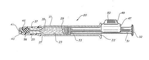
Fig. 1 is a perspective view of the syringe
nasal sprayer of the present invention;
Fig. 2 is a side elevation view of the syringe
nasal sprayer of Fig. 1:
Fig. 3 is a side elevation view of the syringe
nasal sprayer of Fig. 1 viewed from the distal end;
Fig. 4 is a partial cross-sectional view of
the syringe nasal sprayer of Fig. 3 taken along
1 ine 4-4;
Fig. 5 is a cross-sectional view of the
syringe nasal sprayer of Eig. 2 taken along line
5-5;
Fig. 6 is a partial cross-sectional view,
similar to the partial cross-sectional view of Fig.
4, illustrating the syringe nasal sprayer after
one-hal of the medication has been delivered;
Fig. 7 is an enlarged cross-sectional view of
the spray nozzle o~ the syringe nasal sprayer
p-1844
~9
-8- 2~7~
illustrating a two-component spray nozzle assembly
having one-way valve f eatures;
Fig. 8 is a side elevational view of an
alternative embodiment of the syringe nasal sprayer
5 of the present invention;
Fig. 9 is a side elevational view of the
syringe nasal sprayer of Fig. 8 as viewed from the
distal end; and
Fig. 10 is a partial cross-sectional view of
10 the distal end of the syringe nasal sprayer of Fig.
9 taken along line 10-10.
DETAILED DESCRIPTION
While this invention is satisf ied by embodi-
ments in many different forms, there is shown in
15 the drawings and will herein be described in detail
preferred embodiments of the invention with the
understanding that the present disclosure is to be
considered exemplary of the principles of the
invention and is not intended to limit the
20 invention to the embodiments illustrated. The
scope of the invention will be measured by the
appended claims and their equivalents.
Adverting to Figs. 1--7, a syringe nasal
sprayer 20 of the present invention comprises an
25 elongate barrel 21 having an open proximal end 22,
a chamber 23 or retaining liquid and a tip portion
25 extending f rom a distal end 27 of the barrel
having a passageway 28 therethrough communicating
with the chamber.
For the purposes of the description of the
present invention, the term "distal end" is meant
.
P-1844
2~7~ 9
_g _
to refer to the end furthest from the person
holding the syringe nasal sprayer whereas the term
"proximal end'' is meant to refer to the end closest
to the holder of the syringe nasal sprayer.
A stopper 29 is slidably positioned in
fluid-tight engagement in side barrel 21 and is
adopted to engage an elongate plunger rod 31 to
facilitate its operation. The plunger rod projects
proximally from the stopper and extends outwardly
from the open proximal e~d of the barrel. ~he
plunger rod is accessible outside of the proximal
end of the barrel and is provided to move the
stopper along the barrel to force liquid out of the
chamber through the passageway . Specif ically, the
stopper is capable of moving liquid from chamber 23
through passageway 28 upon its movement toward
distal end 27 of the barrel. In this embodiment,
the stopper contains an internal thread (not shown)
which engages an external thread (not shown) on the
plunger rod. There are numerous other construc-
tions that can be used to join a plunger rod and a
stopper such as an interference or snap-fit
arrangement or through the use of adhesives. It is
also possible to make a one-piece plunger stopper
assembly such as by injection molding one or two
materials in a mold cavity. The arrangement
described hereinabove is exemplary of these many
possibilities which are all within the purview of
the present invention.
A disc-shaped plunger rod f lange 32 is
provided on the proximal end of the plunger rod to
perform several functions. One such function is
that flange 32 is a convenient structure for
applying forces to move the plunger rod with
... . . _ . . . .. _ _ _ _
P-1844
-10- ;~Q~ 9
respect to the barrel . The large surf ace area of
the flange reduces the pressure on the fingers
while delivering medication through the nasal
sprayer .
A stopper flange 33 at the distal end of the
plunger rod is provided to supply a large surface
area to transmit force from the plunger rod to the
stopper in a direction toward the stopper, without
damaging the stopper. It will be apparent to one
skilled in the art that there are numerous
constructions that can be used to join a stopper
and a plunger rod and that the arrangement
described herein is exemplary of these many
possibilities. Also, it is within the purview of
this invention to include a one-piece plunger
rod-stopper assembly.
A therapeutic liquid such as liquid medication
35 is contained within chamber 23. A spray nozzle
37 extends outwardly from the tip portion of the
barrel and includes a conduit 3~ therethrough in
f luid communication with passageway 28 . The spray
nozzle includes a distal end 40 having a spray
aperture 41 in f luid communication with conduit 39 .
The spray nozzle of the present invention is
different from nozzles in prior art syringes having
spray adapters in that the instant spray nozzle
includes a means for preventing unpressurized
liquid in the chamber from flowing through the
spray aperture while allowing liquid under pressure
in chamber 23 to flow distally through the conduit
and spray aperture 41. This one-way valve feature
allows the syringe nasal sprayer of the instant
invention to be pref illed by a pharmaceutical
manuf acturer or in the hospital pharmacy and to be
... _ . . . ..
p-1844
2~74;~9
used at a future time or date. The one-way valve
feature isolates the contents of the syringe from
the environment and eliminates the need for other
mechanisms to preclude flow through the distal end
5 of the nasal sprayer.
'rhe spray nozzle of this embodiment comprises
two c~ onPnts, a cap 38 and a flexible valve 45.
Cap 38 is secured to tip portion 25 of the barrel
by virtue of an interference fit between enlarged
portion 43 of tip 25 and interior surface 44 of the
cap . In this ernbodiment the interf erence f it
between the barrel, which is preferably made of
glass, and the cap, which is preerably plastic, is
a preferred way of joining these components. It
should be noted that many materials are suitable
for the barrel and for the cap and that numerous
joining methods such as adhesive, heat sealing, and
the like are all within the purview of the instant
invent ion .
Flexible valve 45 is contained within the cap
between tip portion 25 and distal end 40 of the
cap. Flexible valve 45 interacts with cap 38 to
allow liquid under pressure in the chamber to f low
distally through spray aperture 41 preventing
unpressurized liquid in the chamber f rom f lowing
through the aperture. The valve in this preferred
embodiment is a skirt valve having a circumferen-
tial skirt 46 which will partially collapse under
the force of pressurized liquid in the chamber to
allow liquid to flow from the chambers through the
spray aperture. The skirt collapses by moving away
from the side wall of the cap allowing liquid to
pass through the liquid pressure created gap
between the skirt and the cap.
p--1844
~1~7~9
--12--
Spray nozzles are taught in the prior art and
are commercially available rom numerous manufac--
turers such as SOFA;3 of Paris, France. Spray
nozzles are taught in SOFAB ' s French Patent Appli-
cation ~o . 2, 635, 084 . The valve and cap assembly
of the preferred embodiment is preferably made of
two pieces to reduce cost and simplify assembly.
However, the principle of a flexible skirt valve in
a rigid housing is embodied prior art valves such
as the SOFA~3 valve referred to hereinabove.
Another advantage of the spray nozzle of the
instant invention is that a certain amount of
pressure within chambQr 23 is required before the
valve will open. Accordingly, when the valve opens
(i.e., the skirt collapses), the liquid is
pressurized and is propelled past the valve through
the spray aperture. If the pressure in the chamber
becomes too low the valve will stop the f~ow of
licuid, so that the valve acts as a means for
20 protecting the contents of the syringe during
storage and as a regulator to only allow
pressurized liguid through the spray aperture.
These are important features of the Applicant ' s
syringe nasal sprayer which are not found in prior
25 art nasal spraying devices.
Another important feature and advantage of
preferred embodiment of the present invention over
the prior art is that it cannot be refilled after
use. Accordingly, this invention protects the user
30 from potential infection, contamination or injury
caused by ref illing, using improper procedures, the
wrong` drug or in a non-sterile or contaminated
environment. The single--use feature or means of
the preferred syringe nasal sprayer protects the
.... .. , _ _ _ _
~ r~
p-1844 - -
Z~7~9
-13-
patient by not allowing additional medication to be
drawn into barrel chamber 23 through passageway 28
by placing the spray nozzle in f luid communication
with a liquid medication and pulling the plunger in
5 a proximal direction with respect to the barrel to
create a sub-atmospheric pressure in the chamber.
This method, the most common method of filling a
hypodermic syringe, cannot be practiced with the
instant invention because flexible valve resists
10 liquid flow in a proximal direction. Flow in the
proximal direction is resisted by skirt 46 of
f lexible valve 45 which expands against the walls
of conduit 39 when liquid attempts to move
proximally. Also, pressure differentials which
15 tend to force liquid in a proximal direction will
force the valve against distal end surface 51 of
tip portion 25. To further resist liquid flow in a
proximal direction, the valve may be designed with
a central projection ~not shown) or with a flat
20 proximal or bottom surface so that it will occlude
or block passageway 28 when it is subject to forces
in a proximal direction.
The syringe of the present invention is
intended to be originally ~illed from the open
25 proximal end of the barrel. The stopper is then
inserted using an assembly tool which will allow
air to escape while the stopper is being inserted
into the barrel. Preferably the stopper can be
inserted while the syringe and medication are in an
30 evacuated chamber so that little or no air is
trapped in the chamber when the stopper is
inserted. A syringe so f illed by a pharmaceutical
manufacturer or other entity remote from the
ultimate user is referred to as a pref-illed or
P-1844
2~7~2~9
--14--
pref illable syringe .
Another important f eature and advantage of the
syringe nasal sprayer of the instant invention over
the prior art is that it combines the above-men-
S tioned features along with a means for limiting the
amount of therapeutic liquid delivered to the
patient so that, for example, the dosage may be
divided into equal amounts for each nostril. ~o
perform this function, thQ instant invention
preferably includes dosage limiting housing 47
having a C-shaped cross-section, as best illus-
trated in Fig. 5. Housing 47 partially surrounds
the plunger rod so that the housing will not fall
off the plunger rod urder its own weight but may be
forceably removed from the plunger rod without
eliminating the abilit~ of the syringe nasal
sprayer to deliver medication from the chamber
through the aperture. ~he housing may be designed
with a thin cross-section so that it will def lect
and snap over the plunger rod or the plunger rod
may be designed to deflect under the forces of the
housing. Also, both elements may be designed to
def lect partially during installation and removal
of the hous ing .
Housing 47 is adapted to interact between a
radially extending projection on the plunger rod
such as f lange 32 and proximal end 22 of the barrel
which includes a barrel f lange 26 to limit the
distal motion of the plunger rod with respect to
the barrel. For example, the length of housing 47
can correspond to one-half of the volume of
therapeutic liquid in chamber 23. In use, the
syringe nasal sprayer can be inserted into one
nostril of the patient while it is fully loaded as
_ _ _ _ . .. _ . . .. _ _
P-1844
-15- 2~7~ 9
best illustrated in Fig. 4. Pressure on the
plunger rod 1ange in a distal direction will cause
therapeutic liguid to flow through the passageway
into conduit 39 of the cap, deflecting the skirt
5 portion 46 of the flexible valve, and through spray
aperture 41. The plunger rod will move until its
further distal motion is prevented by contact of
the plunger rod f lange 32 with housing 47 which in
turn contacts barrel f lange 26 . The plunger rod
lO can no longer be moved in a distal direction and
approximately one-half of the therapeutic liquid
still remains in the syringe. To continue to
therapy, the user removes the syringe nasal sprayer
from the one nostril. The user then pulls the
15 housing in direction T, as illustrated in Fig. 6 to
remove the housing from the plunger rod. To
facilitate the removal of housing 47 from the
plunger rod a finger tab portion 49 is provided.
In this preferred embodiment, finger tab 49
20 includes ribs 50 on both sides of the f inger tab to
facilitate gripping the tab. The tab once so
gripped can be pulled in direction T to remove the
hous ing f rom the plunger rod .
With the housing removed, the syringe nasal
25 sprayer may now be placed so that the spray nozzle
is in the other nostril of the patient and the
remaining half of the therapeutical liquid may be
delivered. The dosage limiting housing of the
present invention is an important advantage of the
30 instant syringe nasal sprayer over prior art
devices. The housing does not necessarily have to
divide the dose into one half portions but can be
sized to facilitate any sequence which is thera-
peutically useful for two subsequent doses.
P-1844
-16~ 7~ 9
A housing can also be provided which is
equivalent to the full dose of therapeutic lic~uid
in the chamber so that it is impossible to deliver
any therapeutic liquid until the housing is
removed. This feature is desirable if the syringe
nasal sprayer will be subject to extreme forces and
conditions between illing and time o use because
it physically prevents the orward distal motion o
the plunger rod with respect to the barrel until
time o use. Multiple housings can also be
provided. For example, two housings, each sized to
prevent delivery o one-half o the dose can be
provided so that the syrinqe nasal sprayer will be
protected from forces which could move the plunger
rod during shipping and will be able to deliver two
approximately equal doses of therapeutic liquid at
the time o use.
The instant invention can be used in any
medical application where medication or therapeutic
liquid in a spray form is required such as for
spraying liquid onto the eye or into an open wound
or onto an irritated area such as a burn, and the
nasal application described herein is exemplary of
these many uses.
2s Referring now to Figs. 8-1o wherein an
alternative syringe nasal sprayer 55 is illus-
trated. In this er,~bodiment the structure of the
syringe nasal sprayer is substantially similar to
the syringe nasal sprayer of the emoodiment of
Figs. 1--7. Accordingly, substantially similar
components that perform substantially similar
functions will be numbered identically to the
components of the embodiment of Figs. 1-7 except a
suffix "a" will be used to identiy those
I~ P-1844
Z1~374~9
17--
components in Figs. 8-10.
In this alternate embodiment, syringe nasal
sprayer 55 includes an elongate barrel 21a having
an open proximal end 22a, a chamber 23a for
5 retaining f luid and a tip portion 25a extending
from a distal end 27a of the barrel having a
passageway 28a therethrough communicating with the
chamber .
A stopper 29a is slidably positioned in
10 fluid-tight engagement inside the barrel, an
elongate plunger rod 31a projects proximally from
the stopper and extends outwardly f rom the open
proximal end of the barrel.
A spray nozzle 37a extends outwardly from the
15 tip portion of the barrel and includes a conduit
therethrough. The spray nozzle includes a cap 38a
and a flexible valve 45a. ~he distal end of the
cap includes a spray aperture 41a in f luid
communication with conduit 39a. Internally
20 positioned flexible valve 45a allows li~uid under
pressure in the chamber to f low distally through
the conduit and through the aperture while
preventing unpressurized liquid in the chamber f rom
f lowing the aperture . In this embodiment cap
25 portion 38a is integrally ~ormed with tip portion
25a to produce an integral cap-tip member 51 thus
eliminating another component. In this embodiment,
as illustrated in Figs. 8-10, the barrel, the tip
portion and the cap portion are all one-piece so
30 that the barrel and flexible valve comprise two
pieces .
This embodiment includes means for holding the
f lexible valve in the cap portion so that
sub-atmospheric pressure in chamber 23a will not
. .. _ .. . . . . _
P-1844
-18- 2~7~2~9
pull the valve back into the chamber. In this
embodiment two opposed projections 58 and 59 are
formed inside the passageway to prevent withdrawal
of the flexible valve from its distal position.
S DiffQrent means may be employed to position the
valve depending on the materials and the valve
design employed. These means include adhesive,
ultrasonic welding and the like.
In use the syringe nasal sprayer of the
10 alternative embodiment of Figs. 8-10 functions in
the same manner to deliver a therapeutic liquid as
does the embodiment of the syringe nasal sprayer of
F igs . 1-7 .
The barrel of the present invention may be
lS constructed of a wide variety of rigid materials
such as metals, plastics, ceramics. Glass is
preferred due to its long moisture vapor
transmission rate and compatibility with many
medication formulations.
A wide variety of rigid materials are suitable
for forma~ion of the cap, plunger rod and housing.
These materials includes metals or plastic with
injection molded plastic being preferred.
A wide variety of materials such as natural
rubber, synthetic rubber, thermoplastic elastomers,
thermoplastic and thermosets are suitable for
forming the flexible valve with thermoplastic and
thermoplastic elastomers being preferred.
A wide variety of materials such as natural
rubber, synthetic rubber and thermoplastic
elastomers are suitable for forming a stopper with
natural rubber and butyl rubber being preferred.
Thus the present invention provides a
straight-forward, reliable, easily fabricated
_ _
P-1844
2~ 2~9
-19-
syringe sprayer which provides the simplicity,
ability to store therapeutic liquids and efficiency
of a syringe in a device capable of delivering
medication in the form of a spray without the use
of complex difficult to use medication wasting
adapters and without requiring further assembly at
time of use which can lead to contamination and
misuse. The present invention includes one-way
valve features to prevent ref illing the syringe
10 after use. The present invention also provides
structure to control the amount of medication
delivered to each nostril and to control the total
amount of liquid delivered.