Note: Descriptions are shown in the official language in which they were submitted.
207~72~
TITLE OF THE INVENTION
METHOD FOR RE~ORDING DATA, ~ND PRINTED BODY PRINTED BY THE
NETHOD, AND DATA RECORDING ~EDIUN, AND METHOD FOR READING DATA FROM
DATA R~CORDING THE ~EDIUM
BAC~GROUND OF THE INVENTION
1. Field of the Invention
This invention relates to a method for recording binary data on
a piece of material such as a card and to a printed body whsre data
are recorded by the method.
2. Description of the Prior Art
Heretofore, a bar code system is employed for displaying binary
data on a piece of material.
In this system, data are recorded by arranging a group of
variously patterned black bars and spaces. The recorded data are
read out in such a manner that a light beam emitted from a reading
device is scanned in the direction of a series of adiacent stripes,
light reflected on a piece of material where the bars are printed is
successively detected, and it is transferred into electric signals.
Nowadays, a great deal of data have come to be recorded in such
a bar code. This, however,caused a problem that the reading device
might read out data by Inistake because of a long series of bars.
Further, there is a problem that it is difficult to accurately
arrange spaces between black bars composing a bar code.
To record such data more simply, another method for recording
data is proposed wherein there are formed a ~i-rst bit indicating
. , ,' .' , : ~:
:
, ' :
2~7~2~
field for displaying the first bit of a binary number, a second bit
indicating field for displaying the second bit thereof, a third bit
indicating field for displaying the third bit thereo~, and a fourth
bit indicating field for displaying the fourth bit thereof, the
first through fourth bit indicating fields are individually mar~ed
to produce a code mark as a unit displaying binary data~ and the
code mark is printed on a piece of material(see Japanese Patent
Application Early Laid-open Publication No. Sho 63-132093).
According to the previously proposed method, the cardinal
number 1001 in the binary system (equivalent to 9 in the decimal
system) is recorded by painting out the first and fourth bit
indicating fields, for example.
I~owever, when quite a lot of various data are recorded, such a
code mark type of method still has several disadvantages such as
arrangement of a plurality of code marks, lack of the concealment of
data, or insufficient prevention against forgeries although the
record of data has come to be easily carried out than before.
To overcome those problems, the present invention aims to
provide a method for recording data for recording a lot of data in a
code mark; a data recording medium wherein recorded data are hard to
fade out, they are tightly concealed, and forgerY is not easily
committed; and a method for reading data, as ~ell as a method for
dissolving the difficulty in record of data.
SU~NARY OF THE INVENTION
To achieve the object, a method for recording data of the
-:
207~72~
invention comprises the steps of:
forming a code mark with N (= 1, 2, 3, ...) bit indicating
fields on the surface of a piece of material wherein a binary number
of N bits is recorded;
displaying given bit indicating field,s thereof in the sa~e
color to designate one numeric value ; and
superimposing M (= 1, 2, 3, ...) kinds of colors upon any of
the fields.
According to the method, N kinds of numeric data can be
recorded in a unit consisting of N bit indicating fields.
Further, a printed body printed by the method of the invention
comprises N bit indicating fields of which a unit designates a
binary numbsr of N bits on the surface of a piece oP material, M
kinds o~ colors being superimposed upon any of khe fields, given
fields thereoP being displayed in -the same color to designate one
numeric value .
According to the printed body, N kinds of data can be read out
Prom a unit of N bits indicating fields.
Further, a data recording medium of the invention comprises a
plurality of bit indicating fields, a unit of the fields designating
a binary number on the surface of a piece of material, any of the
fields being painted out with the same dot pattern in pitch to
designate one numeric value of the binary number, any of the fields
being mixedly painted out with different dot patterns in pitch from
the others to designate the binary number.
' -,- ~ . , ~ ' , .. .
'' ~'' ' ' , . ' ,.
. ' - ,''. ' , ' :. ,
207~728
According to the data recording medium, a lot of numeric data
can be recorded by using some kinds of pitches since data are
recorded as a dot pattern of a given pitch.
Further, a data recording medium of the invention comprises:
an opaque sheet on which there are ~rawn fine parallel lines,
latticed lines, or dot patterns for print same or different in pitch
from a transparent reference sheet on which there are drawn fine
parallel lines, latticed lines, or dot patterns for print with a
given pitch,
the opaque sheet being illuminated via the transparent
reference sheet to produce moire fringes relative to recorded data.
~ urther, a method for raading data from a data recording m~dium
of the present invention comprises the steps of:
superimposing a transparent reference sheet whereon there are
drawn fine parallel lines, latticed lines, or dot patterns for print
with a given pitch upon a data recording medium whereon there are
drawn fine parallel lines, latticed lines, or dot patterns for print
same or different in pitch from the transparent reference sheet so
as to form a given angle for producing moire fringes; and
reading out the data of the data recording medium b~ detecting
widths and/or pitches and/or angles of the moire fringes~
~urther, a data recording msdium of the invention comprises:
a transparsnt sheet on whic~ there are drawn fine parallel
Lines, latticsd lines, or dot patterns for print same or different
in pitch from an opaque reference sheet on which there are drawn
~. ~ , ' .. '
2~472~
fine parallel lines, latticed lines, or dot patterns for print with
a given pitch,
the transparent sheet being illuminated via the opaque
reference sheet to produce moire fringes relative to recorded data.
Further, a reading method from a data recordin~ mcdium of the
invention comprises the steps of:
superimposing an opaque reference sheet whereon there are drawn
fine parallel lines with a given pitch upon a transparent da~a
recording medium whsreon there are drawn fine parallel lines,
latticed lines, or dot patterns for print same or different in pitch
from the opaque reference sheet so that both the lines of the
reference sheet and the data recording medium form a given angle to
produce moire fringes; and
reading out the recorded data of the data recording medium by
detecting widths and/or pitches and/or angles of the moire fringes.
Further, a data recording medium of the invention comprises:
a transparent sheet whereon there are drawn fine parallel lines,
latticed lines, or dot patterns for print same or different in
pitch from a transparent reference sheet whereon there are drawn
fine parallel lines, latticed lines, or dot patterns for print with
a given pitcll,
the transparent sheet being illuminated via the transparent
reference sheet to produce moire fringes relative to recorded data.
Further, a Inethod for reading data from a data recording medium
of the invention comprises the steps of:
.
207~72~
superimposing a transparent reference sheet whereon there are
drawn fine parallel lines with a given pitch upon a transparent data
recording medium whereon there are drawn fine parallel lines,
latticed lines, or dot patterns for print same or different in pitch
from the opaque reference sheet so that the lines of the reference
sheet and the data recording medium form a given angle to produce
moire fringes; and
reading out the recorded data of the data recording medium by
detecting widths and/or pitches and/or angles of the moire fringes.
According to the data recording medium and the method for
reading data therefrom, the pitches of moire fringes to be produced
make it possible to detect any combination of the superimposed dot
patterns and accordingly read out the recorded data on the basis of
the dot patterns.
BRIEF DESCRIPTION OF THE DRAWINGS
Fig. 1 shows a code mark according to an embodiment of the
present invention.
Fig. 2 shows a code mark consisting of yellow halftone dots.
Fig. 3 shows a code mark consisting of blue halftone dots.
Fig. 4 shows a code mark consisting of red halftone dots.
Fig. 5 shows the firs~ to fourth bit indicating fieIds of the
code mark of Fig. 1.
Fig. 6 shows a card provided with a code mark according to an
embodiment of the present invention.
Fig. 7 shows cards provided with various sorts of code marks
~7~7~
according to an embodiment of the present invention.
Fig. ~ is a plan view of code marks according to an embodiment
of the present invention.
Fig. 9 is a plan view of a projection screen according to an
embodiment of the invention.
Fig. 10 is a partially sectional view of a device to read out
data of the card of Fig. 7 using the projection screen.
Fig. 11 is a plan view showing an ~xample of moire fringes
produced by superimposing a code mark upon a reference sheet.
~ ig. 12 is graphical representations of detected values of
moire fringes.
D~TAILED DESCRIPTION O~ TH~ EMBODIMENTS
The invention will be described in greater detail hereinafter
relative to non-limitative embodimen-ts and the attached drawings.
Fig. 6 shows a card 1 where data are recorded by a method for
recording data according to a first embodiment of the invention. The
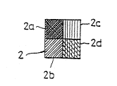
card 1 is provided with a code mark 2. As sho~n in Fig. 1, the code
mark 2 includes a first bit indicating field 2a designating ths
first bit of a binary number, a second bit indicating fisld 2b
designating the second bit thereof, a third bit indicating field 2c
designating the third bit thereof, and a fourth bit indicating field
2d designating the fourth bit thereof.
The first bit indicating field 2a represents "1" or "O" in the
decimal system. That is, by painting out or marking the field 2a,
for example, the code mark 2 records "1" in the dscimal system and
. ' , : '
' ' : ' ' ~
' " . ' "' " ' ' ' ' ' - "
,
2D7~728
without painting out the field 2a, it records "O" in the decimal
system .
The second bit indicating field 2b represents "2" in the
decimal system. That is, by painting out the field 2b, for example,
the code mark 2 records "2" in the decimal system and without
painting out the field 2b, it records "O" in the decimal system .
The third bit indicating field 2c repr~serlts "~" in the decimal
system. That is~ by painting out the field 2c, for example, the
code mark 2 records "4" in the decimal system and without painting
out the field 2c, it records "O" in the decimal system .
The fourth bit indicating field 2d represents "8" in the
decimal system. That is, by painting out the field 2d, or example,
the code mark 2 records "8" in the decimal system and without
painting out the field 2d, it records "O" in the decimal system .
Therefore, when all of the bit indicating fields 2a through 2d
are marked as shown in Fig. 1, the code mark 2 represents "15" in
the decimal system as the sum total of "1" of the first bit
indicating field 2a, "2" of the second bit indicating field 2b, "4"
of the third bit indicating field 2c, and "8" of the fourth bit
indicating Pield 2d. When none of the bit indicating fields 2a
through 2d is marked, the code mark 2 represents "O" in the decimal
system. Thus, the code mark 2 can represent 16 kinds of numeric
data, i.e., "O" through "15" by variously marking the bit indicating
fields 2a through 2d.
In this embodiment, as shown in Figs. 1 through 4, the code
2~7~7~8
mark 2 comprises a yellow code ~ark 3, a blue coda mark 4, and a red
code mark 5. The halftone dots of the three primary colors are
superimposed upon the bit indicating fields ~a through 2d. Green,
brown, or purple, for example9 produced by superimposing the primary
colors upon each other is displayed on any of the bit indicating
fields 2a through 2d, so that it is possible to easily distinguish
a~y combination of the primary colors painted out each field with
the naked eye.
~ or example, the code mark 3 with yellow dots as shown in Fig.
2 represents "0011" in the binary system (equivalent to "3" in the
decimal s~stem), the code mark 4 with blue dots as sho~n in Fig. 3
represents "1001" in the binary system (equivalent to "9" in the
decimal system), and the code mark 5 with red dots as shown in Fig.
4 represents "1100" in the binary system (equivalent to "12" in the
decimal system). The code mark 2 where yellow, blue, and red dots
are superimposed upon each other as shown above includes three kinds
of numeric data, i.e., "0011" "1001" "1100". Therefore, in case of
multiplying the three numeric da-ta together, the number "100100110"
in the binary system (equivalent to "294" in the decimal system) is
recorded. Since the code marks 3, 4, and 5 represent 16 Icinds of
numeric data respectively, the code mark 7. can represent 4096 (=16X
16X 16) kinds of data and thereby a great deal of data are recorded.
To record data, the code marks 3, 4, and 5 may be used independently
of each other, of course.
Therefore, to represent lot numbers of merchandiss, for example,
.
,
2~7~728
4096 X 4096X 4096 (approximatelY 68.7 billion) kinds o~ data are
recorded by providing a card with three code marks each consisting
of the three primary colors.
Alternatively, in two kinds of primary colors including black
and white, halftone dots may be arranged in various ratios to record
a large quantity of numeric data.
Also, it is possible to read out numeriG data from such code
marks with the naked eye by printing the numbers "1", "2","4'9, and
"8", as shown in Fig. 5, on the first through fourth bit indicating
fields respectively for reading them out in the accurate order.
Alternatively, numeric data may bs read out such that the code
mark 2 is scanned with an area type of CCD (charge-coupled device)
camera, as shown in Fig. 6, from a reference mark 6 printed at the
side oi' the first and second bit indicating f'ields 2a and 2b, and
signals detected by the CCD camera are processed with a
microcomputer wherein the pattern of the code mark 2 is previously
memorized to read out the data. In this case, filters with the
three primary colors are disposed in each objective lens optical
system of the first through third CCD cameras and the colors yellow,
blue, red and so on of the code mark 2 are transmitted through the
filters or shaded thereby.
For example, fields painted out in the color yellow is scanned
with the first CCD camera, fields painted out in the color blue are
scanned with the second CCD camera, fields painted out in the color
red are scanned with the third CCD camera, the numeric data recorded
..
.. : , . .' ' :
-
'. : .. .
', , '' ~ ~
2~7~72~
in the code mark 2 are optically read out based on the valuesdetected by the first through third CCD cameras, and the values are
inputted into a microcomputer to transfer the values into the
numeric data.
There~ore, by arranging the compounding ratio of the halftone
dots variously, a great deal of data are allowed to be recorded in a
code mark 2 and also the data can be accurately read out with the
CCD camera.
There will be no~ described each embodiment of a data recording
medium and a method for recording data of the present invention with
reference to the attached drawings.
Fig. 7 shows a card as a data recording medium of the invention.
The surface o~ the card 1 in ~ig. 7(a) is provided with rectangles
or squares 2a through 2d each size of which is equal to the other
and which are disposed at regular intervals of space. The surface
of tl~e card 1 in Fig. 7(b) is provided with several rectangles or
squares of which a pair of contiguous rectangles or squares composes
a unit mark. A code mark comprises these unit marks. The surface
of the card 1 in Fig. 7(c) is provided with a code mark 2 having
four squares 2a throu~h 2d with no space therebetween. Each square
may be sectioned by a deep-colored line with a width different from
that of fine parallel lines used in the squares 2b and 2d. ~ach
square need not necessarily be sectioned by any line, of course.
To record numeric data in Fig.7(a) or 7(b), many striped fine
parallel lines are given to any of squares 2a through 2d.
11
7 ~ 8
For example, the square 2a represents the first bit in the
binary system by giving the parallel lines there, the square 2b
represents the second bit in the binary system by giving tha
parallel lines there, the square 2c repr~sents the third bit in the
binary system by giving the parallel lines thPre. and the square 2d
represents the fourth bit in the binary system by giving the
parallel lines there.
As another e~ample, by giving the parallel lines to each squara,
the square 2a represents "1" and "O" in the decimal system, the
square 2b represents "2" and "O" in the decimal system, the square
2c represents "4" and "O" in the decimal system, and the square 2d
represents "8" and "O" in the decimal system.
In other words, by giving the parallel lines to any of squares
2a khrough 2d, numeric data from "O" to "15" can be represented
according to the code mark 2. The parallel lines in the squares 2a
through 2d may be given uniformly or differently in angle and pîtch
from each other.
Referring to Fig. 8, four blocks of squares 2a through 2d are
each formed as a marking area. Fig. 8(a) shows a code mark 2
consisting of squares 2a through 2d parallel lines of each of which
are drawn in the same direction and in a different pitch from the
other, Fig. 8(b) shows a code mark 2 consisting of squares 2a
through 2d parallel lines of each of which are drawn in a different
pitch and a different angle from the other, and Figs. 8(c) through
8~f) each show a code mark consisting of squares of which only one
12
2~7~728
square has parallel lines. The parallel lines of Figs. 8(c) through
8(f) are similar in pitch and direction to each other and are
arranged in a different block from each other.
Fig. 9 shows a reference sheet 3 comprising a base made of a
transparent film or plate. Regularly pitched parallel linss are
drawn on the base. The lines may be drawn in any transparent or
opaque colors in place of opaque black. The pitch of the parallel
lines in squares 2a through 2d may be either regular or irregular.
For example, when the reference sheet 3 is superimposed upon
the code mark of Fig. 8~a) and is illuminated with light, the
squares 2a through 2d each produce about two to seven moire fringes
(abbreviated to m) independently of the other square. When the
reference sheet 3 is superimposed upon the code mark of Fig. 8(b)
and is illuminated with light, the squares 2a thro~gh 2d each
produce moire frin~es (m) different in pitch and angle from the
other square. When the reference sheet 3 is superimposed upon each
code mark of Figs. 8(c) through 8(f) and is illuminated with light,
one of the squares 2a through 2d, which is 2(a) of Fig. 8(c), 2(b)
of Fig. 8(d), 2(c) of Fig. 8(e), or 2(d) of Fig. 8(f), produces
vertical moire fringes (m) with a regular pitch. The number L of
moire fringes produced by superimposing the reference sheet 3 upon
the code mark 2 is represented as follows:
~ NI
where M is the number of parallel lines drawn on the code mark 2 and
~ is the number of parallel lines drawn on the reference sheet 3.
2~7~28
Fig. 11 is a plan view showing moire fringes (m) produced at
the time when the parallel lines of the reference sheet ~ are
parallelly superimposed upon those of the code mark 2. The moire
fringes (m) are received by photoelectric transfer means. By making
the width of a light transmitting portion between the parallel lines
equal or wider than that of the lines or a light shading portion
(black portion, light absorking portion, or colored portion), such
as in the ratio of 1:1 or 1.5:1, clear discrimination is easily
carried out.
The parallel lines may be colored in such a color tone as black,
red, blue, yellow, or green according to a printing, photographing,
or dyeing method. To discriminate moire fringes more clearly, it is
preferable to conform the color of the lines of a code mark to that
of a reerence sheet.
To read out data recorded in a card 1 arranged as above, the
reference sheet 3 is loaded in a reader as shown in Fig. 10,
Referring to Fig. 10, the reference sheet 3 is supported in
supporting frames ~ and 4 which are provided with a guide 5 for
guiding a card 1 linearly. The reference sheet 3 is made of a
transparent glass plate and has a same or different pitch from that
of the parallel lines of a code mark 2. The code mark 2 of the card
1 is superimposed upon the reference sheet or screen 3. If the same
pitch is employed in the parallel lines of both the screen 3 and the
mark 2, the guide 5 or the screen 3 is set so that the lines of the
screen 3 intersect those of the code mark 2 in order to produce
14
:
-. . .
, . - ' . .
- : :
.
207~72~
moire. Preferably, the angle between the parallel lines and a
guiding direction of the guide 5 is freely selected when the
reference she0t or screen 3 is fixed to the supporting frame 4.
The card 1 is guided by the guide 5 and is moved by a pinch
roller 6 to be slided along the surface of the reference sheet 3. A
light source and photoelectric transfer means (not shown) are
disposed under the screen 3. Light emitted from the light source is
projected onto the screen 3 and then moire fringes (m) produced on
the screen 3 are received by the photoelectric transfer means. For
photoelectric transfer means, a linear type of CCD is employed
whereby detection signals of light reflected from the screen 3 of
the moire fringes (m) are obtained. The detection signals obtained
by the CCD are inputted into a comparator (not shown). The
comparator is in advance made to input reference data for detecting
the number and angle of moire fringes and memorize a memory table of
numeric data corresponding to the reference data. The output of the
CCD is compared to the reference data.
The comparison is carried out in the following way.
As shown in Fig. 12(a), when the CCD detects moire fringes (m),
the CCD outputs output signals of a voltage beyond a given voltage.
Afterthere, a clock pulse counter of the comparator measures tne
length of time of the signals. This measured length is defined as
moire detection value (tm).
Next, the parallel lines (l) in a portion (n) without any moire
fringe are also detected with the CCD. Since the output voltage of
.
2~7~728
the C~D is lower than the given voltage when detecting the parallel
lines (l) with the CCD, the length of time of the output signals of
the CCD is measured with the clock pulse . counterThis measured
value of the parallel lines (l) without any moire fringe is defined
as parallel lines detection value (tl). A low-frequency pulse
counter may be used for a high-frequency area in place of the clock
pulse counter.
A moire detection value per a moire fringe is t~, a parallel
lines detection vaIue in a portion without any moire fringe is tn,
and a detection value of a width (m~n) consisting of a moire fringe
and a portion without moire is tmttn. Therefore, the detection
value is 2X (tm~tn) In the case of two couples of ~ moire frings and
a por-tion without moiro, 3X (tm~tn) in the case of thre~ couples of
a moire fringe and a portion without moire, and PX (tm-~tn) in the
case of P couples of a moire fringe and a portion without moire,
Reference data tlo, tmo, tno, and tmo+tno corresponding to the
detection values tl, tm, tn, and tm~tn respectively, or other
reference data which are obtained by adding allowable values + ~ t
to each of tl, tm, tn, and tm~tn are previously memorized in the
comparator.
As shown in Fig. 12(b), when the values tm, tn, and tm~tn are
within the predetermined reference data, the identification numeric
data of a code mark 2 corresponding to the detection values are read
out on the basis of a msmory table of numeric data corresponding to
the referenc0 data.
`
2~7~72~
Fig. 10 shows that the card 1 is closely superimposed upon the
screen 3. An image of the code mark 2 of the card 1 may be formed
on the line-drawn surface of the screen 3 d;sposed at the middle o~
a lens optical system and the image may be received by the
photoelectric transfer means by properly usin~ the lens optical
system in place of the CCD. Also, the code mark 2 and the parallel
lines of the screen 3 may be allowed to be received by the
photoelectric transfer means through each individual optical system.
In the above comparison method, a code mark formed with various
kinds of parallel lines is discriminated by classifying the
reference data (the count value tO or tO~+ ~t) for discriminating
the code mark into several steps (K steps). A blank space between
code marks each as a unit is distinguished from the parallel lines
of the code marks by detecting the blank space with the CCD whereby
a high voltage area of detection signals of the blank area is
detected longer than that of moire fringes. In the case of a code
mark consisting of rectangles contiguous to each other, the size of
each rectangle is obtained by dividing with the number of the
rectangles contiguous in the pulse count scanning direction.
As a data recording mediuln and a reference sheet of the present
invention, grate-like nets or halftone dots used for print may be
employed in place of parallel lines.
Parallel lines composing a code mark 2 may be displayed by any
combination of the three primary colors so that a plural number of
data can be recorded on condition that the same color designates the
.
2~7~2~
same numeric value.
As a data recording medium, paper tickets, printings, resins,
or labels may be employed in place OI cards.
18
,
.
.
.