Note: Descriptions are shown in the official language in which they were submitted.
CA 02079882 2000-09-11
1
CO;NFOCAL MICROSCOPE
TECHNICAL FIELD
This irwention relates to the field of microscopy
and more particularly t:o scanning confocal microscopes.
The principles of a scanning confocal microscope
are disclosed in United States Patent 3,013,467 of Marvin
Minsky. The basic principle is that illumination of the
specimen or ob;ect to be observed is confined to a
restricted region and observation or detection is confined
to that illuminat=ed region. A complete image is derived by
scanning the speciment or object under observation region
by region through a complete field of view of the
microscope.
Confocal microscopes have better resolution than
conventional microscopes and sharper definition in that out
of focus signals and interference are much reduced. They
have found particular application in the examination of
biological specimens by epi-fluorescence where the
reduction of out of focus interference is a major
advantage.
International Patent Application No. PCT/AU89/
00298 discloses the use of fibre optics in confocal
microscopes of various configurations. The present
invention applies fibre optics to tandem scanning
microscopes in which the returning confocal light is
scanned across a photographic film, a two dimensional CCD
chip or some other photosensitive means in tandem with the
scanning of the illuminating light across the specimen to
produce a real time image. Microscopes of this kind are
CA 02079882 2000-09-11
2
known in which the isolation of the focal plane in the
specimen under observation is achieved in a conventional
lens system by the movement of a series of pin holes or one
or more slits in a very thin sheet of opaque material, the
plane of the sh<=et of opaque material coinciding with an
intermediate focal plane of the microscope system. Such
systems have been described by Petran, Kino and others as
described for example in The Handbook Of Biological
Confocal Microscopy, J<~mes Pawley editor, IMR Press, 1989.
By the present invention, light is carried to and
from the object to be examined by means of one or more
optic fibres which serve as transmitters for the
illuminating light and the returning confocal light. In
some arrangements in accordance with the invention, the
optic fibres provide effective pin holes enabling isolation
of the focal plane in the specimen under observation. In
other embodiments of the invention, the spatial filter
producing the focal plane isolation is not the core of the
fibre itself but is located at an intermediate focal plane
produced by a further lens. In these cases the spatial
filter may consist of a thin sheet of opaque material
coinciding with the intermediate focal plane.
DISCLOSURE OF THE. INVENTION
According to the invention there is provided a
scanning confocal epi-illumination microscope comprising:
a light source;
optical fibre means to receive and transmit
3C~ illuminating light from the light source;
CA 02079882 2000-09-11
2a
a light: condenser for receiving the illuminating
light transmitted via the optical fibre means and for
condensing the illuminating light onto an object to
illuminate an observational field on or within the object
and for receiving light emanating from the observational
field and direci~ing t=hat emanated light back along the
optical fibre means as light returning in a direction
opposite to the illuminating light;
light separator means for separating the
lU returning light from the illuminating light;
returning light receiver means for receiving
returning light from the light separator means and for
exposing a photos;ensit~_ve means to the returning light; and
scanning means operative to move the illuminating
WO 91/15792 ~ ~ ~ ~ ~ ~ PCT/AU91/00129
- 3 -
light in a scanning path relative to said object and
simultaneously to move the returning light in a corresponding
. scanning path relative to the photosensitive means whereby to
cause the photosensitive means to produce from the returning
light an image of the scanned object.
The scanning means may comprise a first scanner to
move the illuminating light as it is transmitted from the
optical fibre means to the object, a second scanner to move
the returning light as it is transmitted from the light
separator means to the light receiving means, and scanner
control means to co-ordinate the scanning movements of the
first and second scanners.
In alternative arrangements, the light separator
means comprises a beam splitter disposed between the light
source and the optical fibre means, the optical fibre means
comprises a bundle of optic fibres extending longitudinally
side by side from a first bundle end which receives light
from the light source to a second fibre bundle end from which
the illuminating light is transmitted to the condenser and
onto which object emanated light is condensed by the
condenser, and the scanning means comprises a light screen
provided with aperture means disposed between the beam
splitter and the bundle of optic fibres at an immediate image
focus plane so that the illuminating light and returning
light both pass through the aperture means and a scan
generator to move the screen and aperture means transverse to
the illuminating and returning light.
In order that the invention may be more fully
explained, some specific embodiments will be described in
some detail with reference to the accompanying drawings.
BRIEF DESCRIPTION OF THE DRAWINGS
Figure 1 illustrates a tandem scanning confocal
microscope constructed in accordance with the invention;
Figure 2 illustrates an alternative form of
scanning confocal microscope constructed in accordance with
. the invention which enables use of a relatively cheap
incoherent light source;
Figure 3 illustrates a further alternative form of
WO 91/15792 PC'f/AU91/00129
- 4 -
microscope also constructed in accordance with the invention
in which scanning is achieved by movement of a single light
screen provided with a slit or a series of pin holes; and
Figure 4 illustrates a microscope similar to that
illustrated in Figure 3 but designed specifically for
operation as an endoscope.
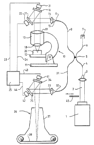
Figure 1 illustrates a scanning confocal microscope
system constructed in accordance with the invention. This
microscope comprises a high intensity light source in the
form of a laser generator 1 to supply a light beam 2 which is
focused by a lens 3 into one end of a flexible optical fibre
4. The other end of optical fibre 4 runs into one side of a
directional coupler 5 which may be of a fused biconical taper
coupler or other coupler for separating light rays travelling
in opposite directions. The light going into one of the
outgoing limbs 6 at the other side of the coupler is absorbed
with minimal Fresnel reflection by an indexing matching media
body 7 while light going into the other leg of the coupler at
that side is transmitted by a flexible optical fibre 8 to
fibre end 9 from which it is transmitted to the optical train
of an optical microscope denoted generally as 10.
Optical microscope 10 comprises a base 11 on which
there is mounted a mechanically adjustable specimen support
platform 12 and a microscope body 13 housing the components
defining the optical train of the microscope: These optical
components comprise a lens 14 to receive the light 15
diverging from the end 9 of fibre 8, a pair of mirrors 16, i7
by which the light transmitted through lens 14 is
successively reflected via a beam converging lens 19 to a
light condenser in the form of a lens 18 which condenses or
focuses the light onto a spot or point observational field in
a specimen 20 supported on the platform 12.
Mirrors 16, 17 can be moved by transducers 21, 22
in response to signals supplied through electrical
connections 23, 24 from an electronic scanning signal
generator 25 such that the reflected light beam is moved in X
and Y directions to cause the illuminated spot to traverse
the specimen in a scanning pattern. Scanning means of this
WO 91/15792 PCT/AU91/00129
2~79~82
- 5 -
kind is used in conventional scanning confocal microscopes.
As well as focusing high intensity light onto the
- specimen to produce an illuminated spot, the condenser lens
18 also receives light emanating from the specimen which is
transmitted back through the optical train of the microscope
to the optical fibre 8. Depending on the nature of the
specimen, this light emanating from the specimen may comprise
reflected light, Raman scattered light or fluorescent light.
It is to be understood that the term "emanating" as used in
10 this specification is to be construed in a broad sense as
covering any light transmitted back from the object through
the condenser.
The returning light reconverges to a focus back at
the tip 9 of optical fibre 8 and travels back up that fibre
to the coupler 5 where a portion of that light is transmitted
via the fourth leg of the coupler and a further flexible
optical fibre 31 to a fibre tip 32.
The separated returning light is collected from tip
32 by a lens 33 and directed by a pair of scanning mirrors
34, 35 to a returning light receiving means 36 in the form of
a camera comprising a camera body 37 fitted with conventional
means to hold a roll of photographic film 38.
Scanning mirrors 34, 35 are moved by transducers
41, 42 in response to signals supplied through electrical
connections 43, 44 from the electronic scanning signal
generator 25 so that the mirrors 41, 42 are moved in exact
synchronism with the mirrors 16, 17. Thus, the separated
returning light is focused as a spot on the film 38 which is
moved in a scanning pattern co-ordinated with the scanning
pattern of the illuminating light on the specimen so as to
develop an image on the photographic film. The two sets of
scanning mirrors are synchronised as exactly as possible so
that the projected spot on the film rasters exactly the same
_ sequence in the microscope stage. A beam chopper 45 may be
provided to intermittently block the laser beam 2 in
synchronism with the scanning mirror but approximately 90°
out of phase to eliminate fly back light and the possibility
of double images caused by slight phase differences between
CA 02079882 2000-09-11
6
the fast scan movements of the two sets of mirrors 16, 17
and 34, 35.
Figure 2 illustrates an alternative microscope
system capable of employing a relatively cheap incoherent
light source such as a mercury vapour globe. Light from the
illumination source 51. is condensed by lenses 52, 53 and
reflected by a beam splitter cube 54 onto the end of an
optical fibre bundle 55. Bundle 55 comprises a large number
of single mode ffibres 56 extending longitudinally side by
side from the bundle end 59 to a remote bundle end 57
fitted with an anti rei_lection glass sheet 58.
The cores of fibres 56 carry illuminating light
coherently and the illuminating light emerges through anti-
reflection glass sheet. 58 as cones of light emerging one
from each of the fib=re cores. These cones of light are
focused by lense:~ 61, 62, 63 into diffraction limited spots
64 (or more accurately Gaussian waists) within a specimen
65 on a microscope stage 66. Between lenses 61 and 62, the
illuminating light pas:~es through a scanner 67 which causes
the illuminated spots 64 to be scanned in a raster pattern.
Scanner 67 which may comprise a pair of reflecting mirrors
and transducers arranged in similar fashion to the scanning
mirrors and trar..sducer.s of the microscope illustrated in
Figure 1 receiver scanning control signals from a scanning
signal generator 68 via electrical connections 69, 70.
Fluorescence generated from within each of the
illuminated spot; or CTaussian waist areas 64 travels back
through lenses 63, 62, 61 and confocally to the same core
in the fibre bundle from which the illumination light
initially came. This returning light then travels back
along the fibre cores and emerges into the beam splitter
CA 02079882 2000-09-11
6a
cube 54 (which may b~~ of the dichroic mirror type) and
passes through a filter 71 which removes any laser light
but passes the Stokes shifted fluorescence which is then
focused by a len~~ 72 onto a photosensitive film 73 within a
camera head 74.
Camera head 74 carries a scanner i5 wnlcn is
generally similar to t:he scanner 67 and receives scanning
movement signals from the signal generator 68 via
~~nnPCti~ns
WO 91/15792 PCT/AU91/00129
- 7 - ~~'~98~2
76, 77. Scanner 75 causes the returning light being focused
onto film 73 to be scanned synchronously with the spots
within the specimen and the scanning movements are
identically oriented with respect to the two sets of fibre
cores at each end of the fibre bundle.
Optically and mechanically the microscope
illustrated in Figure 2 is very similar to that illustrated
in Figure 1 except that a plurality of optical fibres is used
thus permitting the employment of cheaper incoherent light
sources. Preferably, the cladding size of the fibres is
chosen to give the best ratio between the core area and
cladding area to provide an optimal isolation of the focal
plane for a particular set of specimen types.
Figure 3 illustrates a microscope system which
employs a conventional coherent fibre bundle as used in
normal endoscopes. The fibres will accordingly have a much
lower cladding area than the fibres in the bundle used in the
emdobiment of Figure 2. This allows non-laser light sources
to be used and normal endoscopes to be converted to confocal
microscopes. The scanning is carried out by means of
movement of one or more pin holes or slits in a thin opaque
membrane located in an intermediate focal plane allowing
confocal focal plane isolation to be achieved.
The microscope system illustrated in Figure 3
comprises a light source 81 which may be a short arc mercury
vapour lamp. Light from light source 81 passes through a
lens 82 and a filter 83 which isolates a desired spectral
line to a beam splitter 84 comprising a dichroic mirror 85.
The light from source 81 is reflected by mirror 85 to a light
screen 86 which has aperture means 87. The aperture means
may be in the form of one or more slits or one or more
individual pin holes. Light passing through the aperture
means 87 is focused by a further lens 88 onto the end 89 of a
. coherent fibre imaging bundle 91 which may be of the same
kind as used in conventional endoscopy. Lens 88 projects an
image of the slits) or pin holes) 87 in screen 86 onto the
end 89 of fibre bundle 91 and this light is conveyed to the
other end 92 of the bundle where it emerges to be refocussed
WO 91 / 15792 PCT/AU91 /00129
8_
by microscope lenses 93, 94, 95 to one or more lines or spots
on or within a specimen 96 located on a microscope stage 97.
Fluorescence or reflection from the focal plane of the
objective lens 95 goes back through lenses 95, 94 and 93 to
re-enter the same fibres from which the illuminating light
emerged. Light from out-of-focus areas is returned into the
fibre bundle substantially via other fibres within the
bundle.
On emerging from the end 89 of fibre bundle 91, the
returning light is refocussed at the intermediate focal plane
90 at which the light screen 86 is located. The confocally
returned light passes back through the aperture means 87 but
the screen 86 blocks returning light from the out-of-focus
parts of the specimen. The light returned through aperture
means 87 passes through beam splitter 84 and is focused by a
lens 98 onto a film 99 held in a camera head 101.
In the embodiment illustrated in Figure 3, scanning
of both the specimen and the film in the camera is achieved
by scanning movement of light screen 86 as indicated by
arrows 102. Specifically, screen 86 is reciprocated in
directions transverse to the illuminating and returning light
paths. Scanning motion of the screen 86 carrying the
aperture means 87 in the intermediate focal plane 90 allows
the whole of the specimen focal plane to be visualised. A
long pass optical filter 103 may be interposed in the light
path if fluorescence is to be imaged.
Figure 4 illustrates a microscope system which is
essentially the same as that illustrated in Figure 3 and
which like parts have been identified by like reference
numerals. In this case, the microscope is modified by
fitting the outer end of optical fibre bundle 91 with an
endoscope head 110 fitted with a single objective lens 111 in
place of the multiple lens imaging system of the microscope
illustrated in Figure 3. This enables miniaturisation of the
head and endoscopic operation. The microscope otherwise
operates in identical fashion to that illustrated in Figure
3.