Note: Descriptions are shown in the official language in which they were submitted.
WO 92/16147 PCr/US92/021t7
20~2~
Intravascular I~ging Apparatus and ~ethod
BACRGROUND OF THE INVENTION
This invention relates to an ultrasonic
imaging device and methods for usP and manufacture
thereof, and particularly to an ultrasonic imaging
device positionable in coronary vessels to obtain
images thereof.
Ultrasonic imaging of portions of a patient's
body provides a useful tool in various areas o~ medical
practice for determining the best type and course of
treatment. Imaging of the coronary vessels of a
patient by ultrasonic techniques could provide
physicians with valuable information about the extent
of a stenosis in the patient and help in determining
whether procedures such as angioplasty or atherectomy
are indicated or whether more invasive procedures may
be warranted. However, obtaining ultrasonic images of
the distal coronary vessels with sufficiently high
resolution to be valuable for making medical decisions,
such as described above, requires overcoming several
significant obstacles one of the most significant of
which relates to the size of the ultrasonic sensing
device.
Obtaining ultrasonic images of high
resolution o~ a body organ generally requires bringing
an ultrasonic ser.sor (i.e. a transmitter/receiver)
sufficiently proximate to the organ and scanning the
organ with ultrasonic pulses. Ultrasonic imaging of
organs deep within the body that are surrounded by
other, relatively dense organs and tissues requires
WO92/16147 PCT/US92/02117
208~16~ 2 -
connecting a sensor on a probe and positioning the
sensor and the probe near or even into the organ. The
heart and the vessels connected to it are organs of
this type. Because it is a well known t:echnique to
5 insert catheters, guide wires and probes into the
coronary vasculature from remote sites via arteries,
such as the femoral artery, and further because some of
the information of interest to the physician is the
extent of stenosis on the inside walls of the coronary
vessels, it would be desirable to be able to position
an ultrasonic sensor connected to a probe into the
distal regions of the coronary vasculature via a remote
arterial site, such as the femoral artery, to obtain
ultrasonic images of the coronary arterial walls.
The vessels in the distal regions of the
vascular tract that would be useful to image include
the coronary arteries, branch vessels stemming from the
external carotid artery æuch as the occipital and the
arteries leading to the vessels of the head and brain,
~O splenic, and the inferior mesenteric and renal arteries
leading to the organs of the thorax. To be positioned
in these regions, the size of an ultrasonic sensor and
probe must be relatively small not just to traverse the
arterial vessel but also to avoid occluding the vessel
lumen. When a device, such as a catheter, probe, or
sensor, is positioned in a blood vessel, it occupies a
volume which restricts blood flow within the vessel as
well as in vessels proximate thereto. When a device is
positioned within an arterial vessel, the blood flow
through the vessel is restricted to an annular region
(i.e. the area of "ring"-shaped cross section) which is
effectively created between the outer perimeter of the
device and the inner wall of the vessel. ~his would
normally not present a problem in large arteries with
large blood flows, such as the femoral arteries of the
legs, or the aorta, or in very proximal coronary
- .
WO92t16147 PCT/US92/02117
20~21~1
-- 3
arteries. In these large arteries, any restriction
caused by the device would be relatively small and the
blood flow would be relatively large. However, in
small arteries in remote locations, such as the
occipital that leads to the brain, or the coronary
arteries of sizes of 3.0 mm or less that lead to the
right and left sides of the heart, any restriction of
blood flow must be minimized. The consequences of
occluding these small vessels can cause a loss of flow
in the coronary arteries of the heart which may have
several adverse effects, such as severe chest palns, or
physiological changes such as arrythmia, ischemia, and
tachycardiac response. These effects may be
threàtening to the patient and further, once begun, may
be difficult to stabilize.
Moreover, not only are these latter vessels
very small but these vessels are also those in which
there might also be restrictive disorders, such as
atherosclerosis. Atherosclerotic disease as well as
other thrombus formations which occlude blood flow
occurs in these smaller arteries due to the
hemodynamics of the blood tissue interface. Reflecting
this fact is that presently angioplasty is primarily
performed in vessels of a size range of 2.0 to 3.5 mm
~5 in diameter. Such disorders would diminish the cross
sectional area of these vessel lumens even more.
Therefore, a significant obstacle to using an
intravascular probe device to obtain ultrasonic images
of such vessels is that the probe should be
sufficiently small in dimension so as not only to be
positioned in these small, possibly partially occluded
arteries, but also to be sufficiently small so as not
to totally or almost totally occlude the lumen of the
vessel into which it is positioned. Accordingly, for
an ultrasonic sensor device to be used for distal
coronary applications, it must be small enough to be
W092/16147 PCT/USg2/02117
q ~qu?~ f~~ ~ 4 ~
suitably positioned in the coronary vessels and to
permit a sufficient blood flow therearound. For use in
the distal coronary vasculature, the exterior dimension
for a sensor device should be approximately 0.040
inches t1 mmj in diameter to provide an cmnuIar region
of flow in even the most,distal vessels.
Ultrasonic imàging devices intended to be
placed in the vascular system have been disclosed in
prior patents (e.g. U.S. Pat. No. 4,794,93l). However,
these prior devices have had numerous drawbacks that
limited their utility for the most part to uses in only
the peripheral vasculature and not in deep coro~ary
arteries. Prior devices, having diameters ranging from
3.5 French (l.2 mm) and up, would be limited by their
size to only very proximal coronary arteries. Prior
devices, having diameters ranging ~rom 4.5 French
~l.5 mm) and up, would be limited by their size to only
very proximal locations of coronary arteries, peri-
pheral vessels, or very proxi~al organ vessels.
Furthermore, in addition to these limitations, prior
ultrasonic probe devices have produced images lacking
in sufficiently high detail and xesolution to provide
useful information.
There are significant obstacles to making an
ultrasonic probe device with dimensions sufficiently
small to fit into distal coronary vessels and yet
possessing the necessary mechanical and electrical
properties required for high quality ultrasonic images.
For example, in order to position a probe device in a
deep coronary vessel from a remote percutaneous site
such as via the femoral artery, the probe device should
possess a high degree of longitudinal flexibility over
its length. The vessel paths of access to such deep
coronary vessels~ as well as the numerous branches
which stem from these vessels, may be of an extremely
tortuous nature. In some areas within the vascular
WO92/16147 PCT/US92/02117
-- 5 --
2~2~ 61
system, an ultrasonic probe device may have to
transverse several curvatures of radius of 31l6 o~ an
inch (4.7 mm) or less. Thus, the probe device should
possess a high degree of flexibility longitudinally
over its length to enable it to transverse virtually
any curvature of the vascular tract.
Another desired mechanical property for the
probe device is stable torsional transmittance. If the
device is to include a rotating ultrasonic sensor at a
distal end to make radial scans of the entire cross
section of the coronary artery, it should not only be
flexible longitudinally, but should also be stiff
torsionally. Rotation of the ultrasonic device should
be achieved so that a drive shaft extending to the
sensor does not experience angular deflection which
might cause image distortion. Due to the continuous
angular motion which dictates the location at which an
ultrasound sensor scans, if angular deflection occurs
at the distal end of sensor drive shaft, it can result
in an artifact of angular distortion that becomes
apparent on the ultrasound displayed image. This arti-
fact can occur if the rotating sensor drive shaft
experiences "whip". "Whip" may be defined as the
angular deceleration and acceleration of the sensor
drive shaft as a result in shaft angular deflections
during rotation. As the transducer drive shaft is
rotating tt may undergo angular deflection if the drive
shaft's torsional stiffness is low enough to make the
drive shaft susceptible to dynamic changes in torsional
load. It may also undergo angular deflection if the
dynamic torsional loads are high and varying.
During operation, relative changes in
torsional load shDuld be minimal, therefore any induced
'whip' could be attributed to a shaft with a low
torsional stiffness. The acceleration and decelera-
~ions associated with shaft whip can be described by
W092/16147 PCT/US92/02117
~ 6 -
the energy change from kinetic to potential under vary-
ing torsional load conditions. For example, as a
sensor drive shaft encounters additional torsional
resistance its angular velocity drops causing a
deceleration and shaft angular deflection. When the
shaft is free of the added resistance, the energy
stored in the shaft, in the form of potential energy
from the angular deflection and shaft stiffness, is
released causing an angular acceleration and increase
in the shaft's angular velocity.
Image quality and accuracy is dependent on
constant sensor angular velocity. Image construction
assumes a constant sensor velocity, therefore relative
acceleration or deceleration bekween the expected and
actual sensor angular velocity will cause image
distortion.
Even if a sensor possesses the aforementioned
minimal size and mechanical properties, the value of
the device depends upon the quality of the ultrasonic
image which in turn is a direct function of both the
acoustic pulse signal and the electrical signal trans-
mission. Therefore, in addition to the mechanical
properties necessary for locating and rotating a
sensor, the device should also provide a high quality
electrical and acoustic signal. This may include
several specific properties, such as a high signal to
noise ratio of the electronic signal, impedance match-
ing of the overall system without the need for internal
electronic matching components, and minimization of
voltage requirements to attain a signal of sufficient
quality to provide an image.
Accordingly, it is an object of the present
invention to provide a device that overcomes the
limitations of the prior art and which enables the
ultrasonic scanning of small diameter body vessels with
a transducer probe that can be positioned therein.
WO92/16147 PCT/US92/02117
~ 7 ~ 20821~1
It is a further object of the invention to
provide an apparatus, and methods for use and manu~ac-
ture, that enables obtaining ultrasonic image informa-
tion of high resolution or guality.
5 SUMMARY OF THE INVENTION
The present invention provides a device for
intravascular ultrasonic imaging, and methods for the
use an manufacture thereof, comprising an elongate
member with a distal end that can be positioned within
- l0 a vessel of a patient's body while a proximal end is
positionable outside the body. The device also in-
cludes a transducer located at a distal end of the
elongate member and a signal processor connected to a
proximal end of the elongate member ~or generating
pulses to and receiving from said transducer. The
device preferably includes a motor Por rotating the
transducer and a drive cable for connecting the
transducer to the motor and the signal processor. The
drive cable is operable to transmit electrical signals
to and from the transducer.
BRIEF DESCRIPTION OF THE FIGURES
Figure l is a schematic representation of a
presently preferred embodiment of the ultrasonic
imaging apparatus.
Figure 2 is a longitudinal vertical sectional
view of a distal portion of the ultrasonic imaging
apparatus depicted in Figure l.
Figure 3 is a sectional view of the distal
portion of the ultrasonic imaging apparatus along lines
3 - 3' in Figure 2.
Figure 4 is a sectional view of the ~istal
portion of the ultrasonic imaging apparatus al~ng lines
4 - 4' in Figure 2.
W092/16147 PCT/US92lO2117
~3'1.'`~6- 8 -
Figure 5 is a plan view of a portion, parti-
ally disassembled,`of the drive cable.
Figure 6 is a sectional view of an embodiment
of the elongate member of~ the system depicted in Figure
1. ~
Figure 7a a sectional view alone lines 7 - 7'
of the embodiment of the elongate member depicted in
Figure 6 illustrating a first alternative indexing
function construction.
Figure 7b a sectional view alone lines 7 - 7'
of the embodiment of the elongate member depicted in
Figure 6 illustrating a sPcond alternative indexing
function construction.
Figures 8a and 8b are block diagrams of
processing steps related to acoustical indexing.
Figure 9 is a sectional view of the alterna-
tive embodiment of the elongate member shown in
Figure 6 illustrating a first flushing method.
Figure 10 is a sectional view of a second
alternative embodiment of the elongate member illus-
trating a second flushing method.
Figure 11 is a sectional view along lines 10
- }O' of the embodiment in Figure 9.
Figure 12 is a sectional view of a portion of
a third alternative embodiment of the elongate member
illustrating a third flushing method.
Figure 13 is a plan view of the uncoupling
member shown in Figure 1.
Figure 14 is a longitudinal vertical sec-
tional view of the transducer pin assembly shown inFigure 13.
Figure 15 is a longitudinal vertical sec-
tional view of the slip ring assembly shown in Figure
13.
W092/~6147 PCTtUS92/02117
g 2~g2~ 6~
Figure 16 is a plan view with a partial sec-
tional view of the proximal drive cable shown in Fiyure
1.
Figure 17 is a diagram of signal amplitude
ver~us time for the pulser in a first embodiment of the
present inventionO
Figure 18 is a diagram of signal intensity
versus radial distance ~rom the sensor perpendicular to
drive direction.
Figure 19 is a diagram of signal intensity
versus radial distance from the sensor perpendicular to
drive direction.
Figure 20 is a diagram of signal intensity
versus the position along the cross section A - A' of
Figure 18.
Figure 21 is a diagram of signal intensity
versus the position along the cross section B - B' of
Figure 18.
Figure 22 is a block diagram of the
calibrated waveform of ~he pulser.
Figure 23 is a perspective view of another
embodiment of the transducer sensor.
Figure 24 is a plan view of the distal end of
an imaging guide wire which is another embodiment of
the present invention.
Figure 25 is plan view of yet another embodi-
ment of the sensor housing of the present invention.
Figure 26 is plan view of still another
embodiment of the sensor housing of the present
invention.
Figure 27 is plan view of another embodiment
of the present invention for 3-D imaging.
Figure 28 is a view of a distal section of an
alternative embodiment of the elongate member with
variations represented for 3-D indexing.
W092/16147 P~T/U~92/02111
-- 10 --
Figure 29 is a cross sectional view of the
embodiment shown in Figure 28 along lines A - A'.
Figure 30 is a top view of a the distal end
of yet another embodiment of the present inven~ion ~hat
utilizes an alternative drive mechanism.
Figure 31 is an alternative embodiment of
that shown in Figure 30.
Figure 32 is a block diagram of the data and
graphics pipeline of an alternative embodiment of the
present invention.
Figure 33 is a diagram illustrating utiliza-
tion of a neural network architecture in an alternative
embodiment of the present invention.
~ Figure 34 is a side elevàtional view of a
first preferred embodiment of an imaging guide wire.
; Figure 35 is a side elevational view of a
preferred embodiment of a sliced transducer sensor for
use in the imaging guide wire of Figure 34.
~ Figure 35z is a cross sectional view of the
sliced transducer sensor of Figure 35.
- Figure 36 is a top view of the sliced
transducer sensor of Figures 35 and 35a.
Figures 3~, 38, and 39 each show a top view
of alternative const,ructions of the sliced transducer
25' sensor of Figures 35, and 35a..
Figure 40 is a side elevational view of the
preferred embodiment of the transducer sensor for use
in the imaging guide wire of Figure 34 incorporating a
sheath over the transducer sensor.
Figure 40a is a cross sectional view along
line A - A' of the transducer sensor of Figure 40.
Figure 41 is a side elevational view of an
alternative embodiment of the transducer sensor for use
in the imaging guide wire of Figure 34;~incorporating an
exponential matching layer.
WOg2/16147 PCT/~S92tO~117
Figure 41a is a cross sectional view along
line A - A' of the transducer sensor of Figure 41.
Figure 42 is a side elevational view of a
preferred embodiment of the transducer sensor for use
in the imaging guide wire of Figure 34 incorporating a
formed sheath matching layer.
Figure 42a is a cross sectional view along
line A - A' of the transducer sensor of Figure 42.
Figure 43 is a side elevational view of an
embodiment of the transducer sensor for use in the
imaging guide wire of Figure 34 incorporating a splined
attenuation backing support.
Figure 43a is a cross sectional view along
line A - A' of the transducer sensor of Figure 43.
Figure 44 is a side elevational view of an
embodiment of a wedge transducer sensor f or use in the
imaging guide wire of Figure 34.
Figure 44a is a cross sectional view along
line A - A' of the transducer sensor of Figure 44.
Figure 45 is a side elevational view of an
embodiment of a multiple transducer sensor for use in
the imaging guide wire of Figure34,.
Figure 45a is a cross sectional view along
line A - A' of the transducer sensor of Figure 45.
Figure 4~6 is a side elevational view of an
embodiment of the distal tip construction of the
imaging guide wire of Figure34 .
Figure 47 is a side elevational view of an
alternative embodiment of the distal tip construction
of the imagin~ guide wire of Figure 34 incorporating a
locking tip feature.
Figure 48 is a perspective view, partially
disassembled, of an embodiment of the drive c~ble
construction of the imaging guide wire of Figure 34;
Figures 49, 50, and 51 each show a
perspective view of alternative embodiments of the
. .~.
WO92/16147 PCT/VS92/02117
- 12 -
proximal end section of the imaging guide wire of
Figure34 .
Figure 52 is a side elevational view of an
extension wire for use with the imaging guide wire of
Figure 34.
Figure 53 is a side sectional view of a drive
interface for making the electrical an mechanical
connections for driving the imaging guide wire of
Figure.34.
Figures 54a and 54b each show alternative
embodi~ents of supporting means for the proximal end
section of the imaging guide wire of Figur~ i4.
Figure 55 is a side sectional view of a
holder apparatus for the imaging guide wire of Figure
34 -
Figure 56 is a flow chart representing anembodiment o~ the pipeline architecture for the imager
of Figures l or 34 .
Figure 57 is a side sectional view of an
20 alternative embodiment of the slip ring assembly of
Figure 15 incorporating a capacitive non-contacting
slip ring assembly.
Figure 58 is a side sectional view of an
alternative embodiment of the slip ring assembly of
Figure 15 incorporating a magnetic non-contacting slip
ring assembly.
Figure 59 is a side sectional view of an
alternative embodiment of the imager of Figures l or 34
incorporating an EEPROM into the imager to store
essential product information.
Figure 60 is a perspective view of an
embodiment of a cath lab.patient table and accessories
for use with the imager of Figures l or34 .
DETAILED DESCRIPTION OF THE PRESENTLY PREFERRED
EMBQDIMENTS
I. THE SYSTEM
.
... ..
WO92/16147 PCT/US92/02117
20821~1
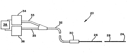
Referring to Figure l, there is depicted a
schematic representation an ultrasonic imaging system
20. The system comprises a sensor assembly 24 located
at a distal end of the system 20 at a distal end ~E an
elongate member 26. The elongate member 26 can be
percutaneously positioned in the cardiovascular system
of a patient via a remote site such as the femoral
artery so the distal end of the elongate member is
located in or close to the remote site while a proximal
end extends out the body of the patient. The elongate
member 26 includes at a distal end thereof the sensor
assembly 24. The elongate member 26 further includes
means for transmitting an electrical signal between the
sensor assembly z4 located at the distal end thereof
and the proximal end extending out of the body of the
patient. The elongate member 26 further includes means
for operating the sensor assembly to make scans of the
remote vessel site. In a preferred embodiment, the
means for operating the sensor assembly 24 and the
means for transmitting a electrical signal to and from
it are provided by a distal drive cable 28 located
inside the elongate member 26. The sensor assembly 24
is connected to a distal end of the distal drive cable
28. The distal drive cable 28 is connected at its
proximal end to a coupling member 30 which connects to
components located at a proximal end of the system 20.
Specifically, the coupling member 30 serves to releas-
ably couple the distal drive cable 28 to, and uncouple
the distal drive cable 28 from, a proximal drive cable
32. The proximal drive cable 32 includes a first leg
33 that connects to a signal processing unit 34 and a
second leg 35 that connects to a motor 36. Connected
to both the signal processing unit 34 and the motor 36
is a control unit 38 that serves to operate the motor
36 and the signal processing unit 34. These components
are described in further detail below.
WO92/16147 PCT/US92/02117
~6~ - 14 -
This embodiment of the present invention is
particularly adapted for ultrasonic diagnostic imaging
in the small, distal vessels of a human patient. These
- vessels typically have diameters of only up to ~.5 mm
diameter. In particular, the present embodiment is
adapted for use in deep organ vessels where the
residual diameter of the vessel may be l.5 mm or less.
However, it should be understood that embodiments of
present invention may be readily adapted for use in
vessels having other dimensions with corresponding
advantages in these other size vessels as well. In the
preferred embodiment for use in vessels having a
diameter of approximately 3.5 mm with potential
stenosis resulting in diameters of down to l.2 mm, the
overall maximum diameter of the distal portion of the
ultrasound imaging system is preferably not more than
approximately 3.2 French (1.07 mm or 0.42 inch) and
pre~erably the distal portion o~ the system has an
overall diameter of less than 3.0 French ~l.0 mm).
In operation, the signal processing unit 34
generates electrical pulses that are transmitted to the
sensor assembly 24 ~ia a proximal electrical transmis-
sion cable inside the proximal drive cable 32 (as
further described below) and the distal drive cable 28.
The signal processing unit 34 also receives electrical
pulses back from the sensor assembly 24 via these
cables. At the same time, the motor 36 operates to
rotate a proximal drive shaft located inside the
proximal drive cable 32 (as described below) which in
turn rotates the sensor assembly 24 to which it is
coupled via the distal drive cable 28. Rotation of the
sensor assembly 24 while pulsing and receiving the
reflections effects an radial ultrasonic scan of the
area proximate to the sensor assembly 24. In this
embodiment, the motor 36 operates to rotate the
transducer assembly 24 at speeds ranging from 500 to
WO92/16147 PCT/US92/02117
- 15 -
20~21~1
1800 RPM, with a preferred rotational speed of
approximately lO00 RPM.
The design and construction of the various
components of the system are preferably computer
modeled and iterated to provide optimum overall system
performance. For example, for optimum performance,
impedance throughout the overall system from the signal
processing unit 34 to the sensor assembly 24 is
carefully matched to eliminate reflections at all
interfaces caused by impedance mismatch. By
eliminating reflections in the system, there is a
faster settling of the pulses since reflections can
cause ringing of the puIse thus reducing the radial
resolution. Because there is limited potential for
adjustment of the impedance at the sensor assembly 24
end of the system, consistent with other requirements,
the rest of the system components proximal from the
sensor assembly 24 are matched to it. In this
embodiment, a system impedance of 50 ohms is selected.
With a system impedance of 50 ohms, readily available
- industry standard components, such as coaxial cablPs
may be used for proximal equipment~ A suitable sensor
can be constructed and used that is matched to this
impedance and that has an active surface area of
0.50 mm2. Similarly, the distal drive cable 28 and the
proximal drive cable 32 are constructed with an
impedance of 50 ohms. The impedance of the coupling
member 30 is not specifically matched to that of the
rest of the system. The coupling member has a low
resistance, e.g. less than 0.5 ohm. However, the
length of the unmatched impedance portion of the
coupling member is made to he only approximately 0.75
inch. At the preferred operating frequency of 30 Mhz,
a segment of this length with an unmatched impedance
can be present in the electrical transmission conductor
of the system without causing a significant reflection.
WO92/16147 PCT/US92/02~17
~ ~ - 16 -
The signal processing unit 34 (including the pulser),
at signal voltage levels, is also selected with
impedance matched to the system impedance, i.e. 50
ohms, to eliminate reflections. With a matched
termination at the signal processing end of the system,
the signal is insensitive to the length of the cable
members. This provides the advantage that the motor 36
and signal processing unit can be positioned out of the
way of the physician, e.g. under a table or other
convenient place.
II. ~HE SENSOR ASSEMBI,Y
Referring to Figure 2, there is depicted a
vertical longitudinal sectional view of a distal
portion of the imaging system 20 including the sensor
assembly 24 of a first presently preferred embodiment.
The sensor assembly 24 is located inside the elongate
member 26. The sensor assembly 24 is connected at a
proximal end thereof to the drive cable 28.
The sensor assembly 24 includes a sensor
housing 40 in which is mounted a transducer sensor 42.
The transducer housing 40 is a hollow, generally
tubular member having a cylindrical wall and open ends.
The housing 40 has dimensions that provide for posi-
tioning and rotating inside of a lumen 43 of the
elongate tubular member 26. In a preferred embodiment,
the housing 40 has an outside diameter of 0.030 inches.
This may be equal to the diameter of the drive cable
28. In a preferred embodiment, the housing 40 is a
metallic tube of 304 stainless steel.
The transducer sensor operates in alternating
pulsing and sensing modes. In the pulsing mode, when
excited electrically, the transducer sensor 42 creates
a pressure wave pulse which travels through the
elongate member into the arterial environment. In the
sensing mode, the transducer sensor 42 produces an
WO92/16147 PCT/US92/021]7
17 ~ 2 08 2l ~l
electrical signal as a result of receiving pressure
waves reflected back to the transducer. These
reflections are generated by the pressure waves
traveling through changes in density in the arterial
environment being imaged. The electrical signals
produced by the transducer sensor 42 are transmitted
back to the signal processing unit 34 for generation of
images of the arterial environment by methods known in
the art and as further described below.
Referring to Figures 2 and 3, the transducer
sensor 42 is constructed from several distinct layers
including a transducer core material 44 having a first
and a second metallized electrically conductive surface
layers, 45a and 45b, bonded thereto, a matching layer
46, a backing layer 47 bonded to the metallized sur-
faces, and one or more adhesive layers. This con-
struction provides a transducer sensor with an active
area of approximately l.0 x 0.5 mm. The impedance of
the transducer is a linear function of the active area
so for a device having an active surface area of about
1.O x 0.5 mm, the impedance is approximately 50 ohm.
Transducer Sensor Core Material:
In a preferred embodiment, the transducer
core 44 of the tranducer sensor 42 is a flat rect-
angular piece of PZT (Lead Zirconate Titarate) typeceramic material. Such PZT material has an acoustic
impedance of mid 20's and a speed of sound of about
5000 m/s. At this speed, the thickness for a 30 MHz
sensor is about 0.003 inch. At this thickness, PZT
materials should be selected with small grain si~es so
that shorts are not generated during processing. The
PZT material is cut to a rectangular shape of 0.5 x
1.25 mm. The active area after wires and a matching
layer are attached is approximately 0.5 x l.0 mm.
WO92/16147 ~ PCT/US92/02117
~ 18 -
Transducer Sensor Conductive Layers:
The first and second conductive layers, 45a
and 45b, are positionqd!:respectively on each face of
the transducer core 44. The conductive layers 45a and
45b may be composed of a number of electI-ically conduc-
tive materials, such as gold, silver, copper, or
nickel. However, a number of other mateI-ials, elements
or alloys are suitable. Additional layers may be
needed under each conductive layer to provide for
adhesion to the core material, e.g., using chromium
under gold. For good performance, the resistance of
the conductive layers should be less than 1 ohm from
one end thereof to the other.
Transducer Sensor Matching Layer:
The matching layer 46 provides an impedanae
transformation between the transducer sensor 42 and the
fluid therearound to allow a better coupling of energy
into the fluid. This transformation is frequency
dependent. A matching layer may be used where a di~-
ference exists between the transducer and the medium
adjacent thereto. Use of a matching layer provides for
a stronger and sharper pulse and thus a better image.
The optimized value range for the matching layer is
from 3.8 to 4.2 (x lO6kg/m2 sec.). The material that is
used for the matching layer may be PVDF (Kynar) at a
thickness of 0.95 x (quarter wavelength thickness).
The matching layer 46 is bonded to the first conductive
layer 45a by means of a thin glue layer. The matching
layer 46 conforms approximately in surface dimension to
the active size of the transducer, i.e. 0.5 x 1.0 mm.
Transducer Sensor Backina LaYer:
Bonded to the conductive layer 45b on the
opposite surface of the core 44 from the matching layer
46 is the backing layer 47. The backing layer serves
WO92/16147 PCT/US92/02117
20821~
to absorb acoustical energy generated off the non
imaging side of the transducer and also helps minimize
energy reflections coming back to the transducer. The
amount of energy traveling from the transducer core to
the backing is a function of the acoustic impedance of
the core and the backing material. The energy that is
generated and enters the backing material should be
attenuated sufficiently before it is reflected back
into the core where it can distort the signal. The
backing layer 47 impedance is selected to provide
optimum damping so that the transducer sensor 42
vibrates for only a short duration after electrical
excitation is stopped and prevents energy from being
reflected to or from the artery wall to the back side
15 of the transducer. This enables the transducer sensor
42 to be ready to receive pressure waves reflected from
the arterial environment with no or minimal interfer-
ence from ringing from the pulse. The impedance of the
backing layer may be determined by computer modeling
and in this embodiment is selected in the range from 5
to 7 (x l06kg/m2 sec.). The composition used for the
backing is preferably a tungsten and silicon rubher
mixture. The acoustical impedance of the mixture can
be varied by mixing various sized tungsten powder
particles into the silicon rubber. This mixture is
very good for backing since it has very high
attenuation. The backing layer 47 may be bonded to the
conductive surface 45b by means of a thin glue layer
applied on backing type material.
The backing layer 47 conforms in surface
dimension to the size of the active area, i.e.
approximately 0.5 x l.0 mm. In order to allow
sufficient ringdown after pulsing, the backing layer 47
is preferably provided with a maximum thickness, or
depth dimension, consistent with the dimensions of the
sensor housing 40, drive cable, elongate member, etc.
WO92/16147 PCT/US92/02117
~6~ - 20 -
As shown in Figure 3, in the present embodiment, the
backing layer 47 may be made to a dimension equal to
the cross-section of the drive cable 28 and/or housing
40. This allows for a backing layer of a maximum size
to provide for sensor ringdown time and ylet is small
enough to fit deep into the coronary arterial environ-
ment. The backing layer may be approximately 0.012
inches in thickness.
The transducer sensor 42 is connected by the
~ides 48 and 49 thereof to the interior of wall 50 of
the housing 40. The transducer sensor 42 is mounted so
that the central axis of the sensor assembly 24 passes
through or is close to the plane defined by the flat
surface of the transducer sensor 42. Thus, the flat
surface of the transducer faces perpendicular to its
axis of rotation. This permits maximizing the
dimensions of the matching layer and backing layer.
This construction also allows for secure mounting of
the sensor assembly 24 to the drive cable 28 by
inserting and connecting the housing 40 to the distal
end of the drive cable 28.
The housing 40 has a first acoustic window
(or aperture) 52 and a second window 53 oppositely
located from each other in the cylindrical wall of the
housing 40. These windows are preferably approximately
rectangular in shape having parallel sides in the
longitudinal direction of the housing 40 and rounded
sides in the chordal direction. These windows may be
formed by removing portions of the material of the
cylindrical wall of the housing but leaving narrow
bands 54 and 55 of the wall 50 of the housing 40 onto
which the transducer sides 48 and 49 may be bonded. In
a preferred embodiment, both windows 52 and 53 are
approximately 0.6 x 2.0 mm. In the sensor assembly 24,
the transducer sensor 42 is mounted and located in the
housing 40 directly facing the first window 52 so that
WO92/16147 PCT/US92/02117
- 21 - 2 0~2l ~l
the ultrasonic signal is emitted from the transducer
sensor 42 through the first window 52.
The size and geometry of the windows are
related to the pulse generating characteristics and the
advantages of the disclosed window geometry are de-
scribed below in conjunction with the description of
the operation of the pulser.
These windows 52 and 53 may a:Lso be useful
during the construction and testing of the sensor
assembly 24. The sensor assembly 24 can be constructed
and tested before mounting to the drive cable 28 by
connecting the wires between the tested sensor and the
tested cable inside the window. This ability to screen
sensor assemblies prior to attachment to the drive
cable increases transducer drive shaft assembly yield
dramatically. Also, the housing design also allows
alignment o~ the transducer in the elongate member
during rotation by the smooth rounded end and fit
between elongate member 26 and the housing 40.
Referring to Figure 4, the sensor assembly 24
is connected at its proximal end to the distal end of
the drive cable 28. Specifically, the first conductive
layer 45a of the transducer sensor 42 is connected to
the distal end of an internal conductor 58 of the drive
cable core wire 60. A distal end of an external
layered coil portion 62 of the drive cable 28 is con-
nected to the housing 40. These connections may be
made by means of an epoxy adhesive. An external
conductor 63 (also referred to as the reference plane
conductor) of the core wire 60 is sealed by means of an
epoxy. The reference plane conductor 63 of the core
wire 60 is connected electrically to the housing 40 via
the external layered coil portion 62 of the drive
cable 28.
In a preferred embodiment, a single trans-
ducer is mounted in a single transducer housing which
WO92/16147 PCT/US92/0211
~ 22
is connected at the distal end of a drive cable.
However, in other embodiments, as described below, more
than one transducer ~ith one or more housings, may be
connected serially at the end of a drive cable in order
to make scans of a length of a vessel. In such multi-
transducer embodiments ! an appropriate switching device
may be utilized in conjunction with the signal ~rocess-
ing unit and the transducers to coordinate pulsing and
receiving data.
10 I I I . DRIVE CABLE
Referring to Figure 5, there is depicted a
portion of the drive cable 28, partially disassembled.
In the assembled imaging system 20, the drive cable 28
is positioned inside the elongate member 26 and is con-
nected to the sensor assembly 24, as described above.The drive cable 28 serves as both the mechanical and
electrical link to the sensor assembly 24.
The drive cable 28 conducts the electrical
signal from the proximally located signal processing
unit 34 (via the proximal drive cable 32) to the sensor
assembly 24 and conveys tha sensed signal from the
sensor assembly 24 back to the signal processin~ unit
34. In order to provide a drive cable of a suitably
minimal dimension for coronary applications while
providing both the necessary mechanical and electrical
properties, the electrical components of the drive
cable provide for mechanical motion transmittance as
well. Thus, the drive cable 28 connects the sensor
assembly 24 to the proximally located motor 36, via a
drive shaft located in the proximal drive cabl~ 32, in
order to rotate the sensor assembly 24 to scan~*he
coronary vasculature with an ultrasonic signal.
In order to provide high quality electrical
signal transmission, the drive cable 28 possesses a
controlled matched impedance, a low signal loss, and
WO92/16147 PCTIUS92/02117
- 23 - 2 082l gl
high shielding and conductivity at high frequencies.
As mentioned above, the n~ed for a matched impedance in
the drive cable 28 follows from the requirement for
matching impedances at interfaces of the overall imag-
ing system from the signal procescing unit 34 to thesensor assembly 24 in order to eliminate reflections.
Because of the relative difficulty in adjusting the
impedance at the sensor assembly 24 end of the system,
the rest of the system components, including the drive
cable 28, are matched to that of the impedance of the
transducer sensor 42. Accordingly, the impedance of
the drive cable 28 i5 matched to that of the sensor
assembly 24 and in this embodiment is established to be
50 ohms.
Mechanically, the drive cable 28 possesses
high torsional stiffness (i.e. minimal angular de~lec-
tion under operating torsional load) yet possess longi-
tudinal (axial) ~lexibility to allow percutaneous posi-
tioning in the coronary vessels. In addition, as
mentioned above, the drive cable 28 also possesses
dimensional properties suitable for positioning in a
patient's coronary vasculature, specifically the drive
cable 28 has a low profile diameter to navigate
torturous coronary arteries. A present embodiment
provides these features in part by a coaxial multi-
layer drive cable construction. The drive cable 28
includes a core wire 60 located inside of an outer
layered coil assembly 62, as explained below.
The core wire 60 is located at the center of
the drive cable 28. The core wire 60 includes an
insulated internal conductor 58. The core wire 60 has
a diameter of 0.014 inch and its internal conductor 58
is 38 AWG (7 strands of 46 AWG) copper wire. The
internal conductor 58 is surrounded by a teflon coating
that forms an insulator layer 66. Teflon is used as an
insulator for the internal conductor 58 of the core
WO92/16147~ PCT/US92/02117
- 24 - ,
wire 60 because of the relatively low dielectric
constant which allows,for a smaller cable, less loss,
and higher speed of electrical transmission for a given
impedance.
Around the insulated internal conductor 58 is
an external conductor 63 in the form of a braided
shield which forms the exterior electrical shield of
th core wire 60. The braided shield is preferably
composed of eight silver-plated, rectangular copper
strands 70, four in each direction of rotation. Spe-
cifically, each strand is 0.001 x 0.007 inch oxygen
free highly conductive tOFHC) copper with 50 micro-
inches of silver plating.
Use of flat wire of these dimensions for the
construction of the braided shield allows exce}lent
coverage of the core wire 60 while maintaining a low
braid profile. This flat wire braid contributes only
about 0.004 inch to the overall cross-section of the
drive cable 28. Furthermore, the 7 ~ill cross-
sectional area of each strand provides enough strengthto form the braid with standard braiding equipment.
The use of flat wire for the braided shield of the
external conductive wire 63 also provides advantages
for electrical transmission through the drive cable 28.
A flat wire braided shield with its inherently large
surface area produces a conductor of low resistance
(i.e. low cable loss) when compared to dimensionally
equivalent round wire braided shields. Because
electrical current travels through a braided shield
~ollowing a path of least resistance, the use of a
rectangular braid for the shield provides a large
surface area at overlapping wires allowing lower
resistance contacts thereat.
Use of silver plating on the external conduc-
tive wire 63 provides several further advantages.
First of all, the silver plating provides a high qual-
WO92/16147 PCT/US92/02117
- 25 - 2 ~
ity environmental seal from corrosion. In addition,
the silver plating an the flat copper wires of the
braided shield of the external conductive wire 63 al50
advantageously reduces the shield's electrical
resistance at the high electrical frequencies due to
"skin effect". Electrical transmission through a con-
ductor wire at high frequencies exhibits a "skin
effect" which is a phenomena wherein the electrical
current tends to increasingly travel in the outer
periphery of a conductor as the signal frequency is
increased. At the frequencies of operation of the
imaging system, most of the current would be carried in
the conductor within less than 0.0005 inch of the sur-
face of the conductor. This is one of the reasons that
the external conductor wire 63 is made with silver
plating because silver has a lower resistivity than
copper. For a given thickness more current will be
carried in a silver layer than in the copper ba~e.
A further reason for ùsing silver plating is
its property of non-corrosiveness which helps maintain
low electrical resistance at the overlapping joints of
the braided shield of the external conductor 63. The
application of the silver plated, braided shield to the
insulated internal wire thus forms a high quality
miniature 50 ohm coaxial cable with a total diameter
less than 0.030 inch (0.75 mm~.
In the drive cable 28, around the core wire
60 is located the layered coil assembly 62. In a
preferred embodiment, the layered coil assembly 62
comprises a multi-layer, multi-strand coil for optimum
torque transmittance. The layered coil assembly 62 of
the present embodiment is comprised of three layers 74,
76, and 78. Each coil layer is composed of three
separate wires strands, e.g. coil layer 78 is comprised
of strands 80, 82, and 84. Each strand may be com-
prised of a 50 micro-inch silver plated, oxygen free
WO92/16147 PCT/US92/02117
~6~ - 26 -
highly conductive ~OFHC) copper ribbon wire having
dimensions of 0.00l x 0.007 inch. This construction of
the layered coil assPmbly provides for suitable torque
transmission (or stiffness) by reducing the torsional
load per strand.
These three layers 74, 76, and 78 are applied
in opposing winding directions to the layer immediately
adjacent thereto. For example, coil layer 74 is wound
in an opposite helical direction from that of coil
layer 76, and coil layer 76 is wound in an opposite
helical direction from that of coil layer 78 (but coil
lay~r 78 would be wound in the same helical direction
as coil layer 74). The coil winding direction is
determined so as to be consistent with the direction of
drive cable rotation so that during operation of the
system, the layered coil assembly will tend to tighten
upon itself thereby providing additional torsional
stiffening ef~ects to the drive cable during operation
without decreasing the cable's longitudinal flexibility
during positioning. Increasing the torque stiffness
reduces the angular deflection per coil layer.
Again, the use of flat wire for the layered
coil assembly has several advantages. Using flat wire
helps in maintaining the low profile of the drive
cable, e.g only approximately 0.028 inch. This is
significantly smaller than would be possible if a round
wire of equivalent inertial moment were used. In
addition, the use of multiple flat wire coils provides
a significant amount of shaft flexibility due to the
inherent slip planes between coils and strands which
facilitates placement of the drive cable in the
coronary arteries.
The utilization of silver plated OFHC copper
for the layered coil assembly 62 advantageously bene-
fits the drive cable's electrical properties as well.The use of the silver plated OFHC copper provides
WO92/16147 PCT/US92/02117
2o&2l~l
shielding effectiveness and lower resistance than other
conductors (both DC resistance and high frequency
resistance due to "skin effect" in conductors). These
properties reduce the electrical signal attenuation
through the drive cable 28 and aid in producing the
cable's matched impedance. These electrical character-
istics improve the overall system performance by
improving the signal to noise ratio and eliminating the
need for impedance matching components.
Manufacturinq Process for the drive cable
The drive cable 28 may be constructed accord-
ing to the following procedure.
First, the core wire 60 is constructed. The
braided shield for the reference plane conductor is
constructed over a 0.0}4 inch diameter teflon insulated
core wire using a Kokubun braiding machine. The
Kokubun braider utilizes 16 bobbins containing braid
wire moving in a inter-twining planetary action to
create an interlaced braid. Bobbin movement, in terms
of orbiting speed, and feed rate of the central core
wire through the braiding area are controlled by two
speed regulated motors, such as Z 1/4 H.P. Emerson
Motors, P/N 3120-406. Motor speed of the core wire
take up pulley and the bobbin rotation are closely
regulated to predetermined values to ensure finished
shaft's mechanical and electrical properties. This may
be done with a Focus 1 Speed Controller.
The following process is ~ollowed to set up
the Kokubun braiding machine. The teflon insulated
internal wire 58 is routed through the center guide of
the braider's bobbin carriage. Due to the fragility of
the internal wire and the ribbon wire to be braided
over it, an additional core wire guiding apparatus
providinq wire support, back tension, and braid wire
entrance angle guiding is added to the Kokubun braiding
WO92/16147 ~ PCTtUS92/02117
~9~ - 28 -
machine. Also, the back tension provided at the
bobbins for the braid flat ~ire has been reduced to
approximately 35% of its original value. A modi~ied
upper guide has been added to control the small
diameter braided wire's movement during the braiding
process.
The Kokubun braider provides positions for 16
bobbins from which to create a 16 strand braid. Eight
of these bobbins are removed to generate a coarser
braid. The eight bobbins removed consist of 4 in each
direction in an alternating fashion such that the
remaining interleaved braid consists of four strands in
each direction.
The braiding machine is started and bobbin
carriage and braid take up wheel motor speed are
adjusted. The bobbin carriage speed is set to 395 +/-
5 RPM. The braid take up wheel speed is set to 530 ~/-
5 RPM. The braider configuration is modified such that
the bobbin carriage motor has been fitted with a 5:1
gear reducer and similarly, the braid take up wheel
motor utilizes a 30:1 gear reducer to provide the
appropriate carriage and take up speeds.
The internal wire is routed through the
braider's main guide and the upper broad guide and
attached securely to the take up wheel.
Bobbins containing the 0.001 inch x 0.007
inch silver plated OFHC copper ribbon wire are threaded
through the upper guide and attached to the braider's
take up wheel, one strand at a time. Using the manual
carriage crank, the bobbin carriage is rotated through
5 full rotations in order to initiate the braid on the
internal wire.
After initiation of the braid onto the
internal wire, the braid is bonded to the core wire
using a cyanoacrylate adhesive over the entire existing
braid length.
WO92/16147 PCT/US92/02117
- 29 - 2 ~ 6'~
The braiding machine is started by simultane-
ously switching on both the carriage motor and the take
up wheel motor. The motor speeds are verified with
respect to their preset values. The braider is then
allowed to operate for sufficient time to produce the
required length of braided core cable based on the
braider's approximate production of 0.33 feet/min.
Upon completion of the braided length, the
braid is bonded using a cyanoacrylate adhesive over 0.5
inch bond length. The braid is cut at the bond area
and removed from the braiding machine. The core wire
- portion is completed.
Next, the layered coil portion 63 is added to
the core wire 60. A length of core wire of 66 inches
is provided. The core wire 60 is prepared for the
addition of the layered coil portion 62 by bonding the
braided wire ends of the external conductor 63 using
cyanoacrylate adhesive over a 0.5 inch length to
prevent unravel of the braid.
The application of layered coil portion 62 to
the core wire 60 is performed using an Accuwinder Model
CW-16A. The core wire is loaded in to the coil winder
head and tail stock chucks. Three spools of 0.001 inch
x 0.007 inch silver plated, OFHC copper ribbon wire are
loaded on the coil winder's spool carriage. The wires
are individually threaded through the coil winder's two
guides and two tensioning clamps and finally through
the three wire, lead angle guide. Wires must be routed
under the three wire guide wheel and over the lead
angle guide. The tensioning clamps are set to light
tension. The spool carriage is moved into its initial
coiling position; it is located such that the lead
angle wire guide is approximately 0.25 inches (axially)
from and head stock, and approximately 0.005 inches
(radially) from the core wire. Guide adjustments are
made by loosening their retaining screws.
WO92/1~147 PCTtUS92/02117
6~
The first multistrand coil 74 is wound with
the coil winder's rotation direction switch in the
clockwise (CW) position. This coil winding rotation
direction requires the three coil strands to ba routed
beneath the core wire and secured to the head stock
spindle.
The coil winding computer controller is
powered on in conjunction with the coil winder itself.
Control by the computer over the coil winder is
lo obtained by initiating the following winding parameters
via the winding program ULTRA_SD: coil pitch=0.0232
inches, maximum winding speed=1780 RPM. The lead angle
at which the wire approaches the core wire is con-
trolled by way of the lead angle guide and the coil
pitch. The winding control program is down loaded to
the coil winder.
Axial tension is slowly added to the core
wire until a value of.3 to .5 pounds-force is reached.
The operating lever is lowered. Using the
speed control knob, the coil winding speed is slowly
increased to a maximum value of 60%. Core wire tension
is continuously monitored during the coil winding
process to maintain a wire tension of .3-.5 pounds-
force.
Coil winding is continued until the lead
angle guide is within 1 inch, axially, of the tail
stock chuck. The coiling process is halted by raising
the operatinq lever and reducing the speed control to
0%. The coils are bonded to the core wire at the head
and tail stock location over a 0.5 inch bond length.
The three strands used to form the coil 74 are cut at
the core wire 60 and care is taken to prevent damage to
the core wire 60. The spool carriage is returned to
the head stock location in preparation for applying the
second, opposing, coil 76.
W092/16147 PCT/US92/02117
- 31 ~ 2 ~8 21 S~
The tail stock pulley is loosened such that
it can move independently of the coil winder drive
shaft. The tail stock spind~e,is rotated 5 full
revolutions in the CcW direction ~when v:iewing the
front of the tail stock chuck) in order to preload the
first coil. The tail stock pulley is tiqhtened.
The three ribbon wires to be coiled are
routed under the three wire guide, over the lead angle
guide, and placed over the core wire; the wires are
lo temporarily secured to the head stock spindle. The
coil winder's rotation direction switch is moved to the
Counter Clock Wise (CCW) position. The operating lever
is lowered and the speed control is increased gradually
to,60%. The core wire tension is maintained at .3-.5
pounds-force.
Coiling is continued until the lead angle
guide is within 1 foot, axially, of the tail stock
chuck. The coiling process is halted by raising the
operating lever and reducing the speed control to 0%.
The coils in this layer 76 are bonded to the core wire
60 at the head and tail stock locations over a 0.5 inch
bond length. The three strands used to form the coil
76 are cut at the core wire 60 and care is taken to
prevent damage to the core wire 60. The spool carriage
is returned to the head stock location in preparation
for applying the third coil 78.
The tail stock pulley is loosened such that
it can move independently of the coil winder drive
shaft. The tail stock spindle is rotated 5 full
revolutions in the CW direction (when viewing the front
of the tail stock chuck) in order to preload the second
coil. The tail stock pulley is tightened~
Ribbon wires to be coiled are routed under
the three wire guide, over the lead guide, and placed
under the core wire; the wires are temporarily secured
to the head stock spindle. The coil winder's rotation
WO92/16147 PCT/US92/0~117
~q~6~- - 32 ~
direction switch is moved to the Cloc~ Wise (CW)
position. The;operating lever is lowered and the speed
control is increased gradually to 60%. The core wire
tension is maintained at .3-.5 pounds-force.
Coiling is continued until the lead angle
guide is within l foot, axially, of the tail stock
chuck. The coiling process is halted by raising the
operating lever and reducing the speed control to 0~.
The coils are bonded to the core wire at the head and
tail stock locations over a 0.5 inch hond length. The
three strands used to form the coil 78 are cut at the
core wire 60 and again care is taken to prevent damage
to the core wire Ç0. The spool carriage is returned to
the head stock location.
Exiting the coil winding computer control
program is accomplished by pres~,ing the escape key
(esc) at the computer keyboard, lowering the operating
lever, and gradually raising the s~ed control above
0%. This sequence will create a user prompt to
continue or exit to the main menu. A "M" is keyed to
return the user to the main menu.
~he completed drive cable 28 is removed from
the coil winder. The remaining coil strands at the
head stock are removed by trimming.
Utilizing the above described method, a
preferred embodiment of the drive cable 28 is provided
having an impedance of 50 ohms, a low electrical signal
loss of lO-12%, and high shie}d and signal conductivity
at high frequencies in the range of lO - 50 MHz ~which
includes the preferred operating frequency of 30 Mhz).
A cable constructed according to the above descxibed
method can possess a relatively low loss, from 0.9 to
l.4 Db loss over the required frequency range. In the
preferred embodiment, the drive cable 28 has a diameter
of 0.028 inch which is suitable for use inside a lumen
WO92/16147 PCT/US92/0~117
_ 33 _ 20~21~
of the elongate member 26 having an internal diameter
of approximately 0.035 inches.
IV. THE SHEATH
As mentioned above, during operation of the
intravascular imaging system 20, the drive cable 28 and
sensor assembly 24 rotate at an angular speed while the
transducer sensor 42 is excited and monitored. In
order to accommodate this rotation in the human body,
the drive cable 28 and sensor assembly 24 are located
in the flexible elongate member 26. The elongate
member 26 is composed of a non-rotating, bio-compatible
sheath that not only encloses both the drive cable 28
and sensor assembly 24 but also serves to position the
transducer sensor 42 at a desired location in the
coronary vasculature. Referring to Figure 6, in the
pre~erred embodiment, the elongate member 26 compr1ses
a tubular sheath 80 having a distal portion 82 that can
be positioned in a coronary artery and a proximal
portion 84 that extends out of the body of the patient.
The proximal portion 84 of the sheath 80 is fixed to a
stationary (non-rotating) component, specifically to a
catheter manifold 85 which in turn is cQnnected to the
housing of the uncoupling member 30 (as described below
and as depicted in Figure 14). As shown in Figures 1,
2, and 4, the sensor assembly 24 is located in a lumen
of the elongate member 26 and specifically in a lumen
86 of the sheath 80 in a distal portion thereof.
In order to permit the transmission o~ the
ultrasonic signal from the transducer sensor 42 which
is inside of the sheath 80 into the body of the patient
(and the reflections back again), the sheath 80, or at
least a distal portion thereof, is made of a material
that is transparent to the ultrasonic signal. In the
present embodiment, the sheath 80 or the distal portion
thereof is made of a TPX material, specifically a
W~92/16147 PCT/U~92/02117
~ ,6~ 3~ -
methylpentene copolymer plastic. The TPX material has
an acoustic impeda~ce~close to water, a low coefficient
of friction, and good mechanical properties. Because
the acoustic impedance of the TPX material is close to
water, very minimal signal reflections are! created at
the sheath/blood interface. This characteristic allows
the TPX material to appear transparent to the trans-
ducer.
In a most preferred embodiment, the shPath 80
is formed of a polyurethane material. In order to mak~
the sheath transparent to the passage of ultrasonic
- waves, the transducer sensor 43 is mounted in the
housing 40 at a slight forward tilting angle, e.g. lO
degrees. This allows for the passage of the ultrasonio
waves through the sheath 80 without reflections.
The sheath 80 is formed having a low profile suitab}e
for positioning in the coronary vasculature. In a
preferred embodiment, the sheath has 80 an external
diameter of 0.040 inch. The TPX material lends itself
easily to the extrusion process and can be readily
drawn to very thin wall diameters. In this embodiment,
the wall diameter of the sheath is 0.0025 and the
diameter of inner lumen is 0.035.
In addition to providing a non-rotating
interface to the body, the sheath 80 furnishes other
~eatures. Because the TPX material has a low coeffi-
cient of friction, it provides a low frictional
resistance bearing surface between the internal drive
cable 28 and the wall of the lumen 86 of the sheath 80.
In addition, the sheath 80 provides
mechanical support to the drive cable 28 in order to
develop good "pushability" for cable manipulation. The
TPX material possesses good mechanical properties for
an extruded copolymer. The mechanical strength of the
TPX material coupled with the axial stiffness of the
drive cable 28 generates a sufficient degree of
WO92/16147 PCT/US92/02117
~ 35 ~ 2 ~8 21 61
"pushability", i.e. structural support :in the sheath
assembly, for positioning the sensor assembly 24 in
coronary arteries.
Located in the lumen 86 of the sheath 80 near
the distal end is an inner lumen seal 87. This inner
lumen seal 87 serves to establish a barrier between the
interior of the sheath 80 and the patient's blood
vessel. This shields the blood vessel from the
turbulence caused by the rotation of the drive cable 28
and sensor assembly 24. When the sensor assembly 24 is
positioned in the sheath 80, the distal end of the
sensor assembly 24 is approximately 0.050 inches from
the inner lumen seal 87.
At a distal end of the sheath 80 is a guiding
tip 88. The guiding tip 88 may be located in the lumen
86 o~ the sheath 80 distally from the inner lumen seal
87. The guiding tip 88 may be comprised of a
radiopaque material, such as a coil of thin platinum
wire. Platinum, with its inherent radiopacity, wound
in a coil configuration produces a soft, flexible,
radio-opaque, crush resistant tip. Mounting the coil
inside the lumen 86 of the sheath 80 permits retaining
the smooth outer surface of the sheath 80 thereby
facilitating maneuvering the sheath 80 through a
guiding catheter and eventually into a coronary artery.
As mentioned above, at a proximal end of the
sheath 80 is located the catheter manifold 85. The
catheter manifold 85 has a first or main port 89 gener-
ally aligned and communicating with the lumen 86 of the
sheath 80 and a second port 90 also communicating with
the lumen 86 of the sheath 80. A strain relief coil 91
is located around the outside of the proximal end of
the sheath 80 and extends into and is bonded between
the sheath 80 and the catheter manifold 85. The
catheter manifold 85 is utilized to connect the sheath
80 to the uncoupling member 30, as described below.
WO92/16147 PCT/US92/02]17
~6~ 36 -
The drive cable 28 is installed into the sheath 80 via
the main port 89. The second port 90 may be used for
flushing of the sheath 80, as described below.
The sheath 80 may also provide for a means of
rotational compensation in order to continuously
calibrate the transducer's angular orientation during
operation. One of the drawbacks associatéd with rotat-
ing ultrasonic imaging devices is angular distortion
between the encoders at the proximal end and the sensor
at the distal tip of the catheter. There are two main
types of the distortions, those changing in time and
those fixed to the phase of revolution. The fixed
distortion is caused by friction or stiffness that
causes a repeatable torque variation with each cycle.
This can be found in almost every rotating element to
some degree. The distortion that changes in time
causes the image to rotate periodically. The major
source of this is the heart moving, which flexes the
elongate member causing a frictional torque variation
synchronous with the heart beat.
The present embodiment provides a solution to
this problem by means of an acoustical indexer. An
acoustical indexer is a locational marking that is put
on, or built into the sheath to provide a rotational
registration. This registration is constructed in the
manner so that it can be readily identified in the
signal processing.
Referring to Figures 7a and 7b, rotational
compensation markers 92 can be incorporated circumfer-
entially in the wall of sheath 80 in a distal portionthereof. The markers 92 may be splines or patterns
incorporated on the interior surface of the sheath 80,
as depicted in Figure 7a, or on the exterior sur~ace of
the sheath, as depicted in Figure 7b. Preferably, the
markers 92 are located at periodic positions 4S degree
from each other around the circumference of the sheath
WO92/16147 PCT/US92102117
~ 37 ~ 20821~
wall. The markers 92 can be made from a variable
thickness in the sheath material, but could be made
from two different materials. These markers 92 may be
formed in the extruding process for the sheath and may
be made just in the region of the sensor or may extend
over the entire length of the sheath. Each wall
thickness change may be recognized by the signal
processing unit 34 and can be used to verify the
transducer's angular position during operation. The
thic~ness steps could be made at various ramp rates.
With a pattern in the sheath wall, the signal process-
ing unit can follow the image variation in distance.
By following and holding steady one edge or feature,
- the time variable distortion is corrected. This com-
pensation ability removes any discrepancy in a image
due to an angular speed change of the transducer.
By using a pattern of acoustic indexing
markers as shown in Figures 7a or 7b where the thick-
ness is varied every 45 degrees, fixed distortions can
be corrected. Periodically, the data of the image
representing the sheath would be analyzed to determine
the correct time spacing of the triggers. This data is
transferred to the pulser that has a variable time
spaced pulse capability. By using a 1000 pulse per
revolution encoder connected to the motor that provides
the synchronizing of the motor to the pulser, there is
more than enough resolution to generate the required
pattern. The screen is divided up into 200 ple shaped
angular divisions, each of these divisions is called a
vector. For a 200 vector screen, the pulser needs to
generate 200 pulses per revolution by dividing up the
1000 pulses into the required spacings.
A block diagram of the indexing data process-
ing is shown in Figures 8a and Bb. A real time con-
figuration tracks an edge in real time and adjusts thepulse pattern very quickly, as represented in ~ig-
WO92/16147 PCTtU592/02117
~ 6~ - 38 -
ure 8a. The data is intercepted from the raw data
pipeline, processed and transferred to the pulser com-
puter. The EKG signal would be useful for calibrating
the image to the heartbeat and removing the time-motion
effect. A non-real time configuration rould be used
almost as effectively, as represented in Figure 8b.
~ere the data is processed and transferred periodically
as needed. The data is captured and processed by the
main processor and the result sent to a pulser computer
that would pulse the excitation at the proper times.
A variation of this method but yielding
basically the same result would apply a pulse to the
sensor every increment of a motor encoder and determine
the position of each vector in the pipeline processing.
Manufacturinq of the Elonqate Member
A sheath 80, as described above, may be made
by first bonding a tubular portion into the catheter
manifold 85 using an epoxy or other suitable adhesive.
The sheath 80 should extend to a distal side of the
entrance of the flush ports into the manifold 85. Care
should be taken to ensure that adhesive does not flow
into the lumen 86 of the sheath. Then the strain
relief coil 91 may be installed into the manifold hub.
The hub is then filled with adhesive. This assembly is
then allowed to cure.
Using an adhesive applicator syringe with a
0.025 inch maXimum diameter tip, the adhesive lumen
seal 87 is installed in the distal end of the sheath
80. The seal 87 is preferably located 0.5 inch from
distal tip of sheath 80. The seal 87 should be 0.100
inch in total length. Next, the distal marker coil is
installed. Using a syringe, adhesive is applied to
0.05 inch of the distal end of the marker prior to
installation. The distal marker is installed in the
distal end of sheath 80. The marker coil is allowed to
W092/16147 PCT/US92tO2117
_ 39 _ 2 V~ 21 S~
interfere with the sheath's seal 87 by 0.05 inch. Then
the assembly is ~llowed to cure at 140F for 4 hours.
flushinq methods
The sheath 80 includes a means for ~lushing
the sensor assembly 24 and sheath lumen B6. Any pres-
ence of entrapped gas or contaminants in around the
sensor assembly 24 reduces the performance of the imag-
ing system. Any gas or contaminants on the surface of
the transducer sensor 42 may generate severe reflec-
tions and essentially blind the transducer in thatregion. The flushing process assures that all gas and
contaminants are removed.
Flushing of the sensor assembly 24 and the
sheath 80 may be provided by three alternative sy~tems:
Referring to Figure 9, a ~irst embodiment o~
the flushing system utilizes a ~lushing lumen 93 which
may be a flexible tubular member having a dia~eter }ess
than the diameter of the lumen 86 of the shea~h 80.
The flushing lumen 93 may be fed through the satheter
manifold's second port 90 proximal to the distal seal
87 of the lumen 86. The flushing lumen 93 is then
pressurized with a flushing medium. The flushing lumen
93 is slowly withdrawn from the sheakh 80 while press-
ure is maintained on the flushing medium. The process
is continued until the flushing medium flows from the
proximal end of the manifold's main port 89 and the
flushing lumen is removed.
Referring to Figure 10 and ll, a second
embodiment of the flushing system is depicted. The
second flushing embodiment uses a sheath 94 having dual
lumens, a main lumen 95 and an outer lumen 96. The
outer lumen 96 provides a flushing channel to the
distal end of the sheath 94 where it communicates with
the distal end of the main lumen 94 through a opening
97 between the lumens 95 and 96. A flushing medium,
W092/16147 PCT/US92/02117
~G~ 40 -
typically water, is continuously fed under pressure
through a proximal catheter manifold's flush port 98
through the flushing lumen 96 from the proximal end to
the distal end, through the opening 97 into the main
lumen 95, and back through the main lumen 95 from the
distal end to the proximal end until the medium flows
from the manifold's main port.
Referring to Figure 12, a thircl embodiment of
the flushing system is depicted. This embodiment in-
cludes a sheath 99 having an air permeable seal l00 inthe sheath's distal tip to allow entrapped gases to
diffuse out during flushing pressurization. The seal
l00 has a permeability which al`lows the air mass in the
sheath lumen to be dissipated through the distal tip
area in a reasonably short amount o~ time. In a com~
plimentary fashion, the seal's porosity is low enough
to restrict water mass transfer, i.e. the surface
tension of the water coupled to the porosity of the
seal prohibits mass transfer. The seal may be made
with materials with permeabilities in the range of: 2
to 2,000,000 ng/(s-m-Pa). This permeability range
covers both flushing pressure variations of 6.895 kPa
to 689.5 kPa and flushing times of l second to 1200
seconds. In the preferred embodiment, permeability for
sheath flushing in 20 seconds at a 202.7 kPa flushing
pressure through a 2.54 mm long seal is 1290.l ng/(s-m-
Pa).
IV. COUPLING AND UNCOUPLING
Referring to Figure 13, the elongate ~em-
ber 26 (with the distal drive cable inside thereof) isconnected at its proximal end to the coupling member 30
by means of the manifold 85. The coupling (and un-
coupling) member 30 connects the distal drive cable 28
to the proximal drive cable 32 vhich in turn connects
to the proximally located components, i.e. the signal
WO92/16147 PCT/US92/02117
- 41 - 2082161
processing unit 34 and the motor 36. By means of the
coupling member 30, the imaging system 20 provides a
means of coupling and uncoupling the dist:al transducer
side of the system from the proximal components at a
point outside the body of the patient.
This coupling member 30 provides several
advantages for the imaging system 20. Providing for
coupling and uncoupling of the distal sensor facili-
tates loading and handling of the drive cable 28 and
the sensor assembly 24 into the elongate member 26.
Also, by providing a means for coupling and uncoupling,
the imaging system 20 can utilize larger size, less
expensive components for electrical and mechanical
transmission proximally from the coupling location
where the dimensions of the components are not limited
by the constraints o~ positioning in the coronary
vasculature. Thus, critical electrical information can
be transferred from the rotating drive cable 28 to a
less expensive, commercially available, stationary,
50 ohm coaxial cable while maintaining a mechanical
link between the motor 36 and the sensor assembly 24.
As required for the rest of components used for
electrical transmission, transfer of electrical
information by the coupling member 30 is preferably
maintained in a controlled impedance environment
matched to the transducer.
At the coupling location, the transmission of
mechanical torque can also be transferred proximally to
larger, commercially available components that are les
expensive to manufacture. Further, at the point of
coupling between the proximal drive cable 32 and the
distal drive cable 28, a mechanical 'fuse' may be pro-
vided to prevent torsional overload to the drive cable
in the body.
In the coupling member 30, the electrical and
mechanical functions which are united in the same com-
WO92/16147 PCT/~S92/02117
~ 42 -
ponents in the distal drive cable 28, are split into
separate, adjacent cables one for the mechanical trans-
mission and another for the electrical transmission
inside the proximal drive cable 32. Thus, in the un-
coupling member 30, the electrical signal transmission,which in the distal drive cable 28 is conducted by the
core wire that is rotating at operating speed, is
transferred to a non-rotating coaxial cable connected
to the proximal signal processing unit 34.
The coupling member 30 may be located
approximately 60 inches proximal of the sensor assem-
bly 24 so that-it is outside of the patient's body.
The coupling member 30 is comprised of a sleeve 101
inside of which is contained a matable coaxial con-
nector pair. The coupling member 30 in this embodiment
o~ the imaging system is provided by two assemblies
that are mechanically coupled together: a transducer
pin assembly 102 that connects to the components on the
distal side of the system, such as the sensor assembly
24 and the elongate member 26, and a slip ring assembly
104 that connects to the components on the proximal end
of the system, such as the signal processing unit 34
and the motor 36.
The coupling member sleeve lO1 is formed by a
first or distal sleeve portion 106 that is part of the
transducer pin assembly 102 and a second or proximal
sleeve portion 108 that is part of the 51ip ring assem-
bly 104. These sleeve portions 106 and 108 may be made
of a metal, such as aluminum. The sleeve portions 106
and 108 are held together through the use of a coupling
nut 110. Accordingly, the coupling nut llO provides
the means for securing the distally located transducer
pin assembly 102 to the proximally located slip ring
assembly 104 and their respective coaxial connector
halves located therewithin together, as described
below, during system operation. This nut 110 may be
WO92/16147 PCT/US92/02~17
- 43 -
2082~
removed or tightened to disconnect or connect the
distal components from the proximally located com-
ponents.
Referring to Figures 14 and 15, the coupling
nut llO slidably fits over the sleeve po:rtion 106 and
abuts against a shoulder 112 on the proximal end of the
sleeve portion 106. The coupling nut llO has threads
114 internal thereto oriented in a proxi:mal direction
to engage corresponding external threads 115 on the
exterior of the slip ring sleeve portion 108, as shown
in Figure 15.
In each of the sleeve portions 106 and 108,
there is provided one half of the matable coaxial con-
nector pair. As shown in Figures 14 and 15, a male
component 116 of the matable coaxial connector pair is
located in the transducer pin assembly 102 and a female
component 117 of the matable coaxial connector pair is
located in the slip ring assembly 104. This coaxial
connector mated pair 116 and 117 provides for both the
electrical and mechanical separation point between the
transducer pin assembly 102 and slip ring assembly 104.
Mechanical coupling between the mated connector halves
- is controlled by the spring force exerted by interfer-
ence between the male coaxial connector shield spring
contacts 118 and the female coaxial connector shell
ll9. This spring force generated between the male and
female components of the matable coaxial pain allows
for torque to be transmitted across the coupling mem-
ber 30. This matable coaxial pair may be a commerci-
ally available coaxial connector pair, such as made byAmphenol Corp., modified to be connected in the
coupling member 30.
This internal coaxial connection is made with
a controlled impedance matched to the drive cable 28
and the transducer sensor 42, i.e. with an impedance o~
50 ohms. Matching the impedance in the coupling member
WO92/16147 PCT/US92/02117
44 -
30 with these components avo ds mismatch signal reflec-
tions, as described above.
Referring to Figure 14, the transducer pin
assembly 102 is connected to th~ proximal end of the
drive cable 28 so as to allow rotation of the drive
cable 28 inside the transducer pin assemb]y 102.
Located at and covering the distal end of the sleeve
portion 106 of the transducer pin assembly 102 is a
sleeve cap 120 having a passage 121 therethrough. The
sleeve cap 120 is secured to th2 sleeve portion 106 by
stamping or a compression fit or other means. The
sleeve cap 120 includes a nipple portion 122 which
extends distally and in which is located the distal
portion of the passage 121. The nipple portion 122 is
connected to or may be formed of the sleeve cap 120.
Threads 128 located on the exterior of the nipple 122
engage internal threads located in the proximal end of
the manifold 85. A compression O-rin~ 129 may be
provided between the distal end of the nipple 122 and
the manifold 85 to ensure a secure fit.
Located inside and connected to the sleeve
106 proximally from the end cap 120 is a coaxial
connector bearing 130 and a bearing retaining ring 131.
The bearing 130 and end cap 120 define an interior
portion 132 of the transducer pin assembly 102. The
bearing 130 may be made of bronze and oil-impregnated
to provide for free rotation inside the pin assembly's
outer shell. A drive cable clamp 134 is secured to the
drive cable 28 so as to be located in the interior
portion 132 of the transducer pin assembly 102. The
clamp 134 may be secured to the drive cable 28 by an
adhesive or other means. A strain relief sleeve 136
may be connected to or formed on the distal surface of
the clamp 134 and extend distally on the drive cable 28
to a location through the nipple 122 (e.y. 0.75
W092/16147 PCT/US92/02117
- 45 -
2082 ~ ~1
inches). The strain relief sleeve 136 may be made of
teflon.
Located around the clamp 134 is a shell 138.
The shell 138 is comprised of a first shell half 139
and a second shell half 140 that can be secured
together such as by means of threads. When the shell
halves 139 and 140 are secured together, they also
secure by compression the clamp 134 between them. The
shell 138 include a distal opening 141 and a proximal
opening 142, both aligned with the passage 121 so as to
receive the drive cable 28. The opening 141 may also
receive a portion of the strain relief sleeve 136. A
bushing 143 may be located in the proximal opening 142.
The bushing 143 may be made of teflon. Connected to
the distal side of the shell 138 is the male portion
116 of the coaxial connector pair~
The drive cable 28 is thus rotatably secured
within the transducer pin assembly 102. The drive
cable 28, the clamp 134, the strain relief sleeve 136,
the shell halves 139 and 140, the bushing 143 and the
male coaxial connector 116 are rotatable.
Referring to Figure 15, there is depicted the
slip ring assembly 104 which forms the proximal half o~
the coupling member 30. In the slip ring assembly 104,
~5 the electrical signal is transferred from rotatable
distal components to non-rotatable proximal components,
i.e. the electrical signal transmission which is
carried by rotating components distally is transferred
to non-rotating components proximally. In addition, in
the slip ring assembly 104, the electrical signal,
which is carried by the same components that transmit
the mechanical torque distally, is carried proximally
by components separate from those that transmit the
mechanical torque.
~5 As described above, the slip ring assembly
104 includes the sleeve portion 108 the proximal end of
WO92/16147 PCT~US92/02117
~ 46 -
which connects`by means of the threads 115-and the
coupling nut 110 to the transducer pin sleeve portion
106 to form the non-rotating coupling member sleeve
101. A slip ring end cap 158 connects to and covers
the proximal end of the slip ring sleeve 108. The slip
ring end cap 158 includes a first opening 160 aligned
centrally therein and a second opening 16:2 o~fset from
the first opening 160. Located in and extending
through the first opening 160 is a slip ring drive
shaft 164. A proximal bushing 166 is positioned in the
first opening 160 around the slip ring drive shaft 164.
An outer slip ring 167 and an inner slip ring 168 are
connected to the distal end of the slip ring drive
shaft 164. The outer and inner slip rings 167 and 168
are connected distally to a modified coaxial connector
170 which forms the proximal portion of female portion
117 of the mated connector pair. A proximal bushing
171 is mounted in the proximal end of the sleeve
portion 108 around the ~emale portion 117 of the mated
coaxial pair.
Through the second opening 162 in the slip
ring end cap 158 extend leads 17Z and 174 from the
proximal drive cable 32. Specifically, the lead 172
connects to the signal conductor and the lead 174
connects to the reference plane conductor of a coaxial
cable in the proximal drive cable 32, as explained
below. The distal end of the lead 172 connects to an
inner brush ring 176 and the distal end of the lead 174
connects to an outer brush ring 178. The inner and
outer brush rings 176 and 178 may be made of brass and
may be approximately 0.063 inch wide. An inner spring
180 is located between the inner brush ring 176 and the
end cap 158 and an outer spring 182 is located between
the outer brush ring 178 and the end cap lS8. The
inner and outer springs 180 and 182 bias the inner and
W092/16147 PCT/US92/02117
_ 47 _ 2 08 2
outer brush rings 176 and 178, respectively, in
distal direction away from the end cap 1580
The inner brush ring 176 bears against a set
of inner brushes 184 and the outer brush ring 178 bears
against a set of outer brushes 186. These two sets of
brushes 184 and 186 ~re mounted coaxially to each
other. In a preferred embodiment, each set of brushes
184 and 186 includes three brushes, (only two brushes
of each set are shown in Figure 15). Each brush is
located at 120 degree intervals to the other two
brushes in its respective set.
The inner set of brushes 184 and the outer
set of brushes 186 are slidably held by a brush guide
188. The brush guide 188 is mounted into the inside of
the slip ring s}eeve 108. The brush guide 188 is a
cylindrical plug having two sets of three slots each
located at 120 degrees from each other (i.e. for a
total of six slots) therethrough for retaining the two
sets 184 and 186 of three brushes each. The brush
guide 188 also includes a large central opening 189
through which passes the slip ring drive shaft 164.
Biased by the inner spring 180, the set of
inner brushes 184 bears against and rides on the inner
ring 168. The inner ring 168 is used to conduct the
signal and is attached to the internal conductor of the
coaxial connector 117. Biased by the outer spring 182,
the set of outer brushes 186 bears against and rides on
the outer ring 167. The outer ring 167 is used for
connection to the reference plane signal and is
attached to the reference plane conductor in the
coaxial connector 117 and/or the sleeve 108.
The brushes provide the path for transferring
the electrical signal information between the station-
ary inner and outer brush rings 176 and 178 and the
rotating inner and outer ~lip rings 168 and 167. In a
preferred embodiment, the brushes are made of silver
WO9Z~16l47 PCT/US92/021l7
'l.~Q~ 4a -
graphite. Silver ~raphite provides for a brush ma-
terial that is highly conductive and self-lubricating.
Relatively large brass slip rings are util-
ized to increase the conductive contact area available
between both the 51ip rings and coaxial connector 117,
and the slip ring and brushes. The use of large
contact areas reduces electrical resistance and signal
loss through the slip ring assembly 104.
In the slip ring assembly 104, only the
coaxial connector 117, the slip ring drive shaft 164,
and the slip rings 167 and 168 rotate during operation.
The sets of brushes 184 and 186, brush rings 176 and
178, brush guide 188 and sleeve 108 all remain
stationary during operation.
Mechanical cou~linq
In addition to providing ~or electrical
transmi~sion, the slip ring assembly 104 also furnishes
the mechanical torque transmission across the coupling
member 30. The springs 18~ and }82 in the slip ring
assembly 104 develop the friction force which supports
the torsional load created by the transducer drive
cable 28. Mechanical coupling between the mated con-
nector halves 104 and 106 is provided by the spring
force generated by the interference between the male
coaxial connector shield contacts 116 and the ~emale
coaxial connector shell 117. This spring force creates
a friction fit between the mated connector pair 116 and
117 and allows torque to be transmitted across ~he
coupling member 30. In the preferred embodiment, the
torque transmittance in the slip ring as~embly 104 is
tuned by adjusting the spring force to provide ~
maximum torque of 3 inch-ounces before relative slip-
page between connector halves 116 and 11, occurs. This
provides for a mechanical 'fuse' feature in the system
W092/16147 PCT/US92/021t7
~ 49 ~ 2082~
that ensures torque transmittance to the drive shaft
assembly and not the pin assembly shell.
The coupling member 30, comprised of the
transducer pin assembly 102 and the slip ring assembly
104, is easy to use and eliminates or reduces obstruc-
tions in the area of the patient. This facilitates the
placement and manipulation of the elongat:e member 26
and sensor assembly 24 in the coronary vasculature of
the patient without the burden of having bulky com-
ponents in close proximity to the patient. The assem-
bled coupling member 30 has a cylindrical shape of
approximately 0.75 inch in diameter and approximately 4
inches in length. (The transducer pin assembly 102 is
approximately 0.75 inch in diameter and 1.75 inch in
length.)
The fact that the slip ring assembly 104 uses
controlled impedance components for electrical trans-
mission except ~or a portion of a length le9s than 0.5
inches. This feature provides for the reduct~on of
signal reflections from impedance mismatches.
V. THE PROXIMAL DRIVE CABLE
The distal end of the proximal drive cable 32
connects to the proximal end of the slip ring sleeve
portion 108, as shown in Figure 15. The distal snd of
the proximal drive cable 32 includes a proximal cable
sheath 190 that connects to the slip ring assembly
qleeve portion 108. The proximal cable sheath 190 may
be formed of a section of heat shrink tubing. Provided
in the interior of the cable sheath 190 are the drive
shaft 192 that connects proximally to the motor 36 and
the proximal coaxial cable 194 that connects proximally
to the signal processing unit 34. The drive shaft 192
and the proximal coaxial cable 194 are adjacent to each
other with the drive shaft 192 aligned approximately
along a central axis of the sheath 190 and the coaxial
WO92tl6147 PCT/US92/02117
~ 5~ -
cable 194 offset therefrom. Proximally from the cable
sheath 190, the drive shaft 192 and the proximal
coaxial cable 194 are enclosed in a proximal cable
covering 195.
The drive shaft 192 connects to the slip ring
drive shaft 164 inside the sheath 190. This connection
is made by means of a shaft coupler 196 which may be a
tubular member made of DELRIN0. As described above,
the slip ring drive shaft 164 extends distally from its
connection to the drive shaft 192 into the slip ring
assembly 104 through the opening 160 in the slip ring
assembly end cap 158. The drive shaft 192 is prefer-
ably longitudinally flexible yet torsionally rigid so
that it can rotate through operation of the motor and
transmit this rotation to the slip ring assembly on to
the drive cable and transducer assembly 24. The drive
shaft 192 may be a flexible cable made of high ten~ile
strength steel or stainless steel. A commercially
available flexible drive shaft may be used, such as
S. S. White Industrial Products, Inc. shaft # 098-9.
Also inside the proximal cable sheath 190 is
the distal end of the proximal coaxial cable 194. The
distal end of the reference plane conductor 198 of the
proximal coaxial cable 194 connects to the proximal end
of the reference plane lead 174 and the distal end of
the signal conductor 200 of the proximal coaxial cable
lg4 connects to the proximal end of the signal lead
172. The coaxial cable 194 is preferably flexible and
is stationary, i.e. it does not rotate with the drive
shaft 192. A matching capacitor 202 may be connected
between the signal and reference plane conductors 200
and 198 of the coaxial cable 194 for impedance matching
purposes. (The matching capacitor Z02 would normally
have a heat shrunk cover, which is not shown in Fig-
ure 15). The proximal coaxial cable 194 may be a
WO92/16147 PCT/US92/Ot117
- 51 - 20821 ~ ~
commercially available 50 ohm coaxial cable, such as
RG 178 B/N, available from Belden Corporation.
Referring to Figure 16, in the! proximal
cable 32, the drive shaft 192 and the proximal coaxial
cable 194 extend proximally from the proximal cable
sheath 190 adjacent to each other inside~ the proximal
cable cover 195. The proximal coaxial cable 194 may be
enclosed in an isolation shield 206 that may be made of
tin plated copper braid. The drive shaft 192 in
enclosed in a non-rotating metallic Cleeve 208. At a
branching member 210, the coaxial cable 194 and the
drive shaft 192 separate. The branching member 210 may
be made of a heat shrink tubing. From the branching
member 210, the coaxial cable 194 extends proximaLly
inside a coaxial cable jacket 212 to coaxial connector
214 that can be fitted to the signal processing unit
34. From the branching member 210, the drive shaft 192
extends proximally ins1de a drive shaft jacket 216 to a
coupling connector 218 to provide for connection to the
motor 36. The motor may be a 40 watt DC rare earth
motor, such as manufactured by Maxon Motor Co., Model
No. RE035-071-39EAB200A.
V. THE PULSER AND SIGNAL PROCESSING OPERATION
The signal processing unit 34 includes a
pulser which generates the high energy pulses that are
converted by the sensor into an acoustical wave that is
used for imaging. A ~ull single cycle pulser is used
since it gives twice the energy as a half cycle pulser
for the same peak voltage and further it gives better
settling. For isolation between the high voltage
circuitry and the elongate member, a transformer is
used. High frequency transformers are easier to design
for cyclic waveforms with no DC freguency component, if
fast settling is important. A full single cycle pulse
3S of the sensor generates a return signal with almost no
W092/16147 PCT/US92/02117
~ 52 -
increase in rlngdown time as compared to an impulse.
Any increase in the number of cycles beyond one
increases the ringdown time almost directly propor-
tionally.
For a good image, signal quality is very
important. This means high amplitude with ringdown
quickly to a -4OdB level. A pulser technique is
utilized that provides for a sharper pulse and better
ringdown of the signal. Prior pulsers implement a
pulse shape of an integer number of half cycles at a
given frequency. A pulser that is capable of gener-
ating a pseudo-random pulse would be able to excite the
transducer and settle the reflections out by the
sequence of pulses at certain amplitudes and at the
right time.
As mentioned above, the size and shape of the
sensor window is directly related to the quality o~ the
ultrasonic image obtained. U}trasonic imaging in two
dimensions, (i.e. of a cross section of the arterial
wall) is acoustically a three-dimensional problem.
Referring again to Figures 2 - 4, the objective for a
good imaging system is to have a thin sharp rotating
beam over the distance of interest, e.g., in a
direction, y, radial to the artery wall. However, the
beam, of course, propagates in all directions. The
performance of the beam in the two lateral directions
from the radial direction is termed the acoustical
optics of the sensor. In the two lateral directions x1
and x2 (i.e. the directions perpendicular to the radial
direction), the beam shape is a function of the
distance from the sensor, sensor focus, physical shape
and the operating fre~uency. For an imaging device
that makes circular scans of the arterial walls, the
resolution in the radial direction is limited by the
number of cycles of propagation of the pulse waveform.
This time or distance is determined typically by the -
WO92/16147 PCT/US92/02117
- 53 ~
40 dB amplitude points of the waveform, as illustrated
in Figure 17.
Using a rectangular transducer sensor is one
of the keys to making a very small intravascular ultra-
sound device for use deep in the coronaries. There aresome tradeoffs with respect to circular apertures, but
at the very small sizes the best performance is
obtained from a rectangular aperture.
The beam shape is a function of the housing
aperture size in the respective direction. This
function is
Z = A2/L
where Z is the near field distance, A is the aperture
size, and L is the wavelength. For the above 0.5 x
l.0 mm window with a 0.056 mm wavelength (as defined by
the frequency and media speed of sound), the near field
is l.l mm in the x dlrections and 4.5 mm in the y
direction. The signi~icance of the near field is that,
for an unfocused sensor, the beam width is nearly the
aperture width through the length of the near field.
In the near field the beam is rapidly changing in all
directions. This is from the constructive and destruc-
tive interference patterns. In the far field the beam
is more uniform and diverges. The far field behaves as
though the source was a point source. For ~ocused
crystals the peam can be focused up to the limit of the
near field. A focused beam is narrower in the focused
region but diverges faster than unfocused outside this
region.
For intravascular ultrasound in the coronary
region, it is sought to obtain images out to about 5 mm
in radius. For a window having dimensions such as
described, an advantage of the rectangular shape is
that even though the energy is spreading in the x
directions, the energy in the y direction remains
relatively constant through the distance of the region
WO~2t16147 PCT/US92/02117
~6~ 54 -
of interest, as illustrated in Figures 18 - 21. In the
x directions, or lateral directions as used in this
specification, the beam size is ~uite usable to gener-
ate good intravascular images throughout the radius of
interest. For a circular aperture of this size, the
intensity would decrease very rapidly since the beam is
spreading uniformly in all directions. The rectangular
aperture has better distance vs. energy dropoff along
with a larger surface area. For apertures 0.S mm and
smaller the rectangular shape has some characteristics
that are more desirable for apertures than circular
shapes.
Calibrated Waveform Pulser:
As mentioned above, for radial resolution the
ringdown of the signal is very important and it would
be desirable to have a single cycle response to a
impulse excitation. Typically, the excitation that is
used is either a half cycle type impulse excitation or
a integer number of sine wave cycles.
There are significant advantages to using an
excitation that uses a main pulse rather than a
modified pulse waveform to cause a faster -40 Db ring-
down time. There are two major reasons for this. From
computer modeling of the transducer, the resultant
objective of the iterative optimization program is to
generate a system transfer function that has a smooth
phase and magnitude over the widest frequency range.
This is achieved by optimizing the value of peak pulse
amplitude s~uared divided by the integral of time
weighted magnitude after the peak. By using a non-
impulse excitation, the Fourier transform of the
excitation is different so that the frequency spectrum
of the excitation is different than an impulse. The
ideal impulse has constant magnitude frequency com-
ponents. By allowing the computer to vary the waveform
WO92/16147 PCT/US92/02117
_ 55 _ 2 0~2l ~ 1
from one discrete time increment to the next, anoptimum excitation waveform can be generated.
There are limitations of the computer model,
such as non-infinite backing distance, surface
irregularities, mechanical tolerances, impedance mis-
matches, etc. These variables result in the perfor-
mance of the actual device to depart from what the
model predicts. By using basically the same technique
to calibrate a device, certain reflections and imper-
fections can be countered by using an optimized excita-
tion.
This circuit could be implemented using a
high speed Digital to Analog (D/A) converter, where the
output could be programmed by a computer to a predeter-
mined wave form, (see Figure 22). This output could beamplified to any required level that is required. The
optimized waveform is generated over a few hundred
nanoseconds and is settled out before the image data is
received.
VI. ADDITIONAL PREFERRED EMBODIMENTS
A. Sensor constructions:
Referring to Figure 23, there is depicted an
alternative embodiment for the construction of the
transducer sensor. In constructing a sensor, it is
desirable to have a configuration that gives a uniform
beam from one device to the next and is easy to
produce. A uniform beam is necessary for both good
repeatability of system performance as well as for
implementing other, more advanced data conditioning
algorithms necessary for image enhancement.
Referring to Figure 23, there is depicted an
alternative embodiment of the transducer sensor. As in
the embodiment described above and illustrated in
Figures 2-4, the transducer sensor in Figure 23 is com-
prised of a several separate layers including a trans-
WO92/16147 PCT/US92/02117
208~
- 56 -
ducer core, conductive layers bonded to either side
thereof, a backing layer and a matching layer. In the
embodiment shown in Figure 23, a matching layer 301
(which may be composed of a PVDF material) is larger in
dimension than sensor core 44 and includes a overhang
303 on a proximal end. This overhang 303 allows
electrical contact between the conductive surface 45a
over the sensor core 44 and the center conductor of the
coaxial drive cable (not shown). This provides for
both a superior transducer surface with a very uniform
active area. This embodiment also significantly
facilitates manufacturing. These features can be fur
ther enhanced through the use of a conductive backing
305. The conductive backing 305 provides an electrical
contact between the sensor back surface and the sensor
holder. The sensor holder is electrically connected to
the drive cable outer conductor (not shown). The con-
ductive backing can be composed o~ a number of di~fer-
ent materials, such as silver, tungsten, copper, gold
or a number of other elements or alloys. The matching
layer 301 can be made from PVDF, or other materials.
Other alternative embodiments include using a
PVDF type material having a conductive layer on both
the front and back face of the sensor to carry the
signals to their connection. Behind the layer on the
back side of the sen~or an attenuating layer may be
needed to absorb the energy coming off in that
direction. The two connections would be terminated at
the drive cable coaxial electrical connections. A
further alternative is to extend the conductive faced
matching layer and the conductive faced backing layer
from the sensor core to the proximal portion of the
drive cable by integrating the flexible circuits into
the construction of the drive cable. In order to
electrically insulate the two conductive surf~ces, an
insulation layer is incorporated between ther~ayers.
WO92/16147 PCT/US92/02117
- 57 -
208~
This would require no joints in the electrical sensor
construction within the catheter.
B. Imaqina Guide wire
An alternative embodiment of the present
invention may combine the functions of a guide wire
with those of an ultrasonic imager. A guide wire
function is to navigate to a location of interest in a
patient~s vasculature and to position a catheter over
the guide wire into place for a procedure, such as
balloon angioplasty. Because it would be desirable to
- have a device that would image the artery before,
during and after such procedures, it would be advant-
ageous to combine the functions of the guide wire and
the imaging device. Most catheters are of a coaxial
design so that once the catheter is in place the guide
wire could be withdrawn and an imaging guide wire put
in its place.
Currently guide wires are used in dimensions
of 0.018 inch or smaller. In the embodiment described
above, the drive cable 28 has a diameter of 0.026
inches and accommodates a transducar sensor having an
active area of approximately 0.020 x 0.040 inch. In
order to combine the functions of the drive cable with
those of a guide wire, the dimensions of the drive
cable would be reduced in size to approximately 0.018
inch in diameter. The transducer sensor would be made
with a housing aperture close to 0.017 inch. At that
size the image resolution would be substantially the
same as in the embodiment described above. With image
enhancement techniques described elsewhere in this
specification, it would be possible to have an image as
good as or better than those currently achieved. A
thinner transducer having a higher frequency or a
different material could be used for the sensor.
:,
.
WO92/16147 PCT/US92/02117
58 -
A distal end of an imaging guide wire 350 is
illustrated in Figure 24. A drive cable 352 can be
constructed substantially as described above, except
that for reducing the size from 0.026 inch to 0.018
inch, two coils and a double braid would be used
instead of three coils and an eight wire braid. This
has the result of reducing the outer coils and con-
ductors to 0.008 inch leaving O.OlO inch for a center
conductor and insulation.
In one aspect, the construction of the
imaging guide wire would likely depart from that of the
embodiment described above and that is in the mounting
of the transducer sensor to the drive cable. In the
imaging guide wire, the width of the active area o~ the
sensor would be nearly equal to the diameter of the
drive cable. In all other respects, the construction
of the transducer sensor portion of the imaging guide
wire would be very similar to that of the embodiment
described above. This drive cab}e 352 has a sensor
holder 354 mounted at the distal end thereof. Unlike
the sensor housing described above having oppositely
located windows, the sensor mount 354 of this embodi-
ment would not include a second window located
oppositely from the transducer opening. Instead, the
mount 354 would provide physical support under the
transducer sensor 356. Also, due to size constraints,
there would be little room ~or backing materia} on the
back side of the transducer sensor. This could be com-
pensated for by several different methods. For
example, the sensor could be made from a copolymer
material which has a low acoustic impedance so that no
matching layer would be needed to couple to the fluid
and further the impedance difference between the
backing support and the sensor material would be large
enough so much less energy would enter into the back~ng
compared to PZT directly mounted. Alternatively, the
W092/16147 PCT/US92/02117
~ 59 2 0821~ 1
energy that enters into the back support can be some-
what dissipated and scattered by using a material such
as a porous sintered type metal for the backing support
and canceling out reflections with a calibrated pulse
waveform. A major problem with copolymer materials is
the lower D33 coefficient. (D33 is the dielectric
constant in the thickness direction.) This makes a
sensor of the same surface area have a larger
impedance. This impedance difference could be com-
pensated for by using some of the techniques describedelsewhere within this specification or active circuitry
could be placed next to the sensor to buffer the signal
to a lower impedance.
PZT materials can also be used in the imaging
guide wire embodiment, but they would likely need a
front matching layer and a back decoupling layer. The
backing con~iguration may include a hal~ wave decoupler
where its impedance is low with respect to both the
sensor and backing support. This backing decoupler
would work in the opposite manner from that of the
matching layer, i.e. where a quarter wave }ength aids
in coupling, a half wave length thickness helps in
decoupling energy transfer between two impedances.
In the imaging guide wire, the electrical
connections would be made through the backing support
to the back side of the sensor and to the ~uter
conductors of the drive cable. The front connection
would be made the same way as in the embodiment de-
scribed above. For the copolymer alternative, con-
nections would be made using one o~ the center drive
cable wires and connecting the leads directly to the
metallized copo~ymer surface using conductive epoxy or
low temperature solder.
l. Imaginq Guide Wire - Overall construction
The imaging guide wire, as described herein,
is an intravascular imaging device having an ultrasonic
WO92/16147 PCT/US92/02117
~ 6~ - 60 -
sensor located at a distal end of an intravascular wire
sized and adapted to be located within the guide wire
lumen of conventidnal catheters used for intravascular
procedures. As such, the imaging guide wire has
several significant advantages. For example, the
imaging guide wire can utilize the path provided by the
guide wire lumen of a conventional cathet:er to image at
the arterial location to which the cathet:er is
advanced. Moreover, in several embodiments, the
imaging guide wire may be provided with conventional
guide wire features, e.g. a floppy spring tip, to
enable the imaging guide wire to be used as both a
conventional guide wire for positioning an
intravascular catheter as well as imaging features,
e.g. a sensor, to enable imaging the intravascular
regions accessible thereby.
In order to be utilized in the above
described manner, an embodiment of the imaging guide
wire 450 is provided, as shown in Figure 34. The
imaging guide wire 450 includes a tip section 452, a
sensor section 454, a drive cable section 456, and a
proximal connector section 458. As mentioned above, an
essential requirement for the imaging guide wire is
that it possess an outer profile of a size that allows
it to fit through a guide wire lumen in conventional
interventional catheters. In catheters that use
OWPWPCCOMSPECPROMPT@ @^W^A^N*Y. Further, the drive
cable section 456 should be very straight.
Electrically, the drive cable 456 is preferably capable
of sending a signal from one end to the other with
minimum loss. In order to properly match the sensor
impedance, high impedance in the drive cable 456 is
preferred. The electrical impedance of the drive cable
456 is preferably in the range of 20 to l00 ohms.
An embodiment of the drive cable 456 is
illustrated in Figure 48. The drive cable 456 includes
WOg2/16147 PCT/US92/02117
- 61 _ 2 ~ 2l 6l
a core wire 564, an insulation layer 566, a shield
layer 568, and a coil layer 570. The core wire 564 may
possess several alternative constructions. In one
embodiment, the core wire 564 is formed of a solid
wire. AlternativPly, the core wire may ~e formed of
multi-strand copper or silver-plated copper wires. The
latter embodiment provides good electrical
characteristics and allows the drive cable 456 to be
relativley floppy. However, a multi-strand
construction may not provide sufficient longitudinal
stiffness. Therefore, the core wire may preferably be
formed of a material having a high modulus of
elasticity thereby increasing the longitudinal
stiffness. Materials like stainless steel, tungsten,
and beryllium copper are preferred. Of these, tungsten
is most preferred since it has the highest yield
strength and the highest conductivity.
To provide ~or low electrical loss in the
core wire 56~, a high conductivity material is applied
to the outer surface of the core wire 563. Preferred
materials for applying to the outer surface of the core
wire 563 include silver or copper. Silver is most
preferred since it has the highest conductivity. These
materials are easily plated to a thickness suitable for
~5 good electrical transmission. At high frequencies,
electrical current stays close to the surface of a
conductor and therefore a O.OOl inch of conductor
plating over the core wire is su~icient. In a
preferred embodiment, taking into account both
mechanical and electrical requirements, the ideal
thickness of the coating is less than O.OOl inch.
The insulation layer 566 in the imaging guide
wire separates the conductive core layer 564 from the
conductive shield layer 568. For electrical purposes,
this layer 566 is nonconductive and preferably has as
low of an dielectric constant as possible. If a solid
WO92/16147 PCT/US92/021t7
~ 62 -
wire is used for the core wire 564, it is preferred
that a means be in,corporated into the insulative layer
566 to restrict lon'gitudinal motion between the core
wire 564 and the outer coil 568. If the :insulative
layer 564 is made of Teflon, a direct bond may be
difficult to make between the layers. In this case,
movement between the core wire 564 and the outer layers
can be restricted at the joint between the drive cable
456 and the sensor housing 354. This is preferably
accomplished by using a nonconductive sleeve to bond
between the core 564 and outer layers that will be
- connected to the sensor housing 354. This sleeve is
made out of glass ceramic or other hard, nonconducting
material. To bond between the'layers along the length
of the drive cable, holes are formed in the Teflo~ at
various patterns to allow glue or other bonding
material to be used to connect the layers together.
A material other than Teflon can be used for
the insulation layer 566. Such other materials include
glass strands or a solid extrusion of glass, kynar
strands, or a ceramic extrusion. The extrusions would
form a solid, uniform layer over the core wire out to a
given diameter. The strands would then be expoxied to
form a composite layer much like a fiber glass or other
composite structure that uses fiber and binder to
generate a unique high strength material.
The shield layer 568 is located over the
insulating layer 566 to make up the outer layer of a
coaxial signal cable. The shield 568 can be made from
a braid of wires or a coil of wires. In a preferred
embodiment, these wires are rectangular silver-plated
copper wires. A single layer of coils may be used to
provide the smallest diameter drive cable. A low
resistance shield layer provides for RF emission
shielding and susceptibility. Cable loss is a function
of the core and shield total resistance, and
WO92/16147 PCT/US92/02117
- 63 - 2 ~ 2l ~'l
accordingly, it is desirable to provide the shield with
as low resistance as possible. For this reason, it is
preferred that a braid or double coil is used for the
shield layer.
The outer coil layers 570 are needed for good
torque transmission for performing the functions of
both the drive cable and guide wire. The outer coil
layers 570 are formed of copper or alternatively other
metals like stainless steel. In a proximal section of
the outer coil layer 570, a binder is used to bind all
the layers together over a length thereof so as to make
that portion of the imaging guide wire straight and
stiff. This proximal section is from the proximal
connector of the imaging guide wire to a location
corresponding the end of the guide catheter with which
the imaging guide wire would be used. This distance is
typically 130 cm. This allows the distal section of
the imaging guide wire to be relatively more flexible
wherP it needs to go through tight bends.
Another alternative way to provide additional
stiffness in a proximal section of the imaging guide
wire drive cable 456 is to provide another layer of
material over the metal coil outer layer 570 along a
proximal section. This additional layer may be formed
of other-than-metal strands of glass, kevlar or other
high strength materials. The strands would be used in
a coil or braid layer over the core cable 570. The
strands could then be epoxied to form a composite layer
much like a fiber glass or other composite structure
that uses fiber and binder thereby resulting i~ a
unique, high-strength material. As described above,
this can be a dual section composite in which ~nP
section is made out of one fiber and binder and the
other section the same or different fiber and ~inder or
a combination thereof.
WO92/16147 PC~/US92/~117
64 -
5. Imaqinq Guide wire Proximal section
Referring again to Figure 34, a proximal
section 458 of the imaging guide wire provides several
functions. These functions include a connection for
electrical contacts for signal transmission, torque
transmission during imaging, torque and longitudinal
moWPWPCCOMSPECPROMPT@ Q^W^A^N*Yrovided and used in
quadrature, thereby allowing the directi~n to be
determined. For absolute position information, gray
scale encoding may be preferable. Gray scale coding
has the property that only one bit changes in going
from one state to the next. This prevents errors
compared to binary scale for example, since there is no
way of ensuring in binary scaling that all bits will
change simultaneously at the boundary between two
encoded values for binary or other codes.
Patterns for both radial acoustic indexing
and 3-D lateral indexing may coexist on the sheath.
Both patterns could be formed of the sheath material or
could be formed of different materials. One pattern
could be formed on the inner side of the sheath while
the other on the outer side. Also, these patterns
could be formed on the same surface.
F. H~draulic Drive and Acoustic Indexinq: -
Using acoustical rotational indexing allows
determination of the sensor angular position inde-
pendent of the proximal angular position of a
mechanical drive shaft or cable. With this capability
means other than a mechanical drive shaft can be used
to scan the vessel with a rotating acoustic beam. In a
further embodiment of the present invention depicted in
Figure 30, there is provided a rotating imaging device
408 for scanning of a vessel of a patient with a
rotating acoustic beam that is driven by means other
than a mechanical drive cable. In the embodiment
WO92/16147 PCT/US92/02117
- 65 - 208~
shown, a rotatable mirror 410 is driven by a rotating
hydraulic source 409. The rotating hydraulic source
may be a jet and fin type turbine 412. The turbine 412
would propel the mirror 410 in a rotational direction.
The speed of rotation of the mirror 410 could be
controlled by varying the fluid flow rate. Using
fluid, the rotation of a mirror 410 would be very
smooth since there wou~d be little friction from
rotating shafts compared to mechanical drive devices.
Bearings 414 could be provided to provide for smooth
rotation. Feedback to the pulser for pulsing and speed
monitoring would be provided~using an acoustical
indexing pattern 4l6 on the sheath in the rotational
direction as described above. A transducer sensor 418
could be mounted either distally or proximally from the
mirror and aimed to direct an acoustic pulse toward the
angled face of the rotating mirror 410.
This configuration provides advantages for
combining other functions into the device. With no
moving parts over most of the length of the device,
there is available substantial room to add other
features. For example, it would be possible to
integrate a balloon onto the device. The hydraulic
course would already be present, and if the balloon is
ported to the same fluid usecl for driving the mirror,
all that would need to be done to inflate the balloon
would be to control the input pressure independent of
the output flow rate. This could control both the
inflation pressure as well as the mirror rotation
speed.
In a further embodiment, a rotating sensor
420 could be used instead of a rotating mirror by using
a slip xing holder 422 to couple the signals to and
from the rotating sensor 420 to a signal cable on a
catheter, as shown in Figure 31. A hydraulic turbine
424 would drive this device ~ust as described in the
WO92/16147 PCT/US~2/02117
~ 66 -
embodiment above with the mirror. As in the previous
embodiment, an acoustic encoding pattern 426 would be
included on the sheath portion of the device. This
embodiment has the advantage that the sensor 420 could
be designed with a thin backing with a hole there-
through large enough for admitting a guide wire 428
through the center of the device. This would provide
for over-the-wire placement of the device.
G. Data Gra~hics Pi~eline Architecture
In ultrasonic intravascular imaging, a large
amount~of data needs to be processed between the
transducer being pulsed and the image being displayed
and various means can be used for this processing. For
example, processing can range from all analog to all
digital. In most digital systems, the conditioned
signal is acquired through data ac~uisition, processed
by a computer, and displayed through some graphics
hardware. This can be accomplished over a computer
buss as long as there is a limited amount of trans-
ferring being done. Current systems are very basic inthe digital conditioning and image processing, and can
utilize this approach.
It would be preferred to use digital condi-
tioning functions to enhance the ultrasonic image or to
provide for feature extraction. This would likely
require a di~ferent data flow architecture to provide
for additional data transfers needed to produce the
image reasonably guickly. Figure 32 depicts a pipeline
structure that provides this architecture. This
architecture includes a dual pipeline: one for raw data
and another for graphics data. The analog input from
the sensor/conditioning is acquired from a high speed
data acquisition circuit. This circuit synchronizes
the raw data pipeline and transfers the data down the
pipeline at a lower speed. The data is passed from one
WO92/16147 PCT/US92/02117
- 67 - 20821~1
function to the next in real time or near real time
speeds. This pipeline basically processes polar data.
Since there would be much less data in the polar
domain, it would be preferable to process this data as
much as possible. These processing functions may
include deconvolutions, fourier transform processing,
neurocomputing processing or other techniques to
enhance the raw data and do feature extraction.
At the end of the raw data pipeline, the data
is converted to a graphics data stream through a large
"look up table" (LUT). This LUT essentially performs a
polar to rectangular conversion. There are other ways
to generate the graphics data from the raw data, but
this is the preferable method. The graphics data can
then be handled in the graphics pipeline. Processing
functions performed here are those that preferably
should be done in rectangular instead of polar
coordinates. These may include edge detection, area
calculations/manipulations, logical pixel edge smooth-
ing, other area operations, and image overlays.
This architecture is ideal for intravascularimaging applications since the data can be acquired and
processed from one function to the next with minimal
time delay. The pipeline structure is very flexible
for feature enhancements and additions, all that needs
to be done is to change a cable between the appropriate
location to add a new pipeline function. This struc-
ture can accommodate a variable number of pipeline
elements, as needed. Some of these pipeline functions
include the provision for recording and playback of raw
data. Also, a function may be provided for the
buffering of raw data as the catheter is advanced or
withdrawn through the guide wire lumen of the
interventional catheter. This would provide the
physician with information about the entire artery from
the incision location to the coronaries. This data
WO92/16147 ~6~ PCT/US92/02117
- 68 -
.,,, :,
would likely not need to be viewed at the time it is
obtained, however, it would be available for analysis
off line after the procedure. The raw data can be
stored on an optical disk, e.g. a WORM, that can store
up to l Gbyte of data. It is estimated that during the
relatively short period of time that the imaging guide
wire is being advanced or withdrawn through the guide
wire lumen of the catheter, the data is being generated
at a rate of approximately lO0 Mbytes/minute.
A small variation on this architecture would
include the addition of parallel pipelines. This could
be done for example by taking the raw data acquisition
output, branching off to a second LUT, and combining
the two at the initial graphics pipeline function.
This would allow two displays o~ the same raw data at
the same time in different locations on the screen.
This would be desirable if a real time enhanced display
is desired while at the same time showing a slower 3-D
reconstruction or enhanced feature detection.
The data pipeline and graphics pipeline
architecture, as described above, are advantageously
integrated into a system environment. Figure 56 shows
the pipeline structure integrated into one type of
system environment. Figure 56 shows how the
communication portion of the architecture can be
implemented to allow the central system CPU to handle
pipeline setup and configuration. This allows user
input to effect changes in overlays, images and signal
conditioning of data. Not every pipeline function may
require a direct interface to a common buss. ~An
alternative to common bussing is daisy-chained
communications. Here, the common processor w~uld be
able to perform the setup and configuration t~sks using
a serial or parallel communication link. An external
controller may be provided in the overall system
configuration. This controller may issue commands to
W092/16147 PCT/US92/02117
2~821 61
- 69 -
the system or may be directly memory-mapped to the
functions on the system. This intersystem
communication may employ techniques known and accepted
to those of skill in the art. In the f:irst method, the
external controller may be connected in a serial or
parallel manner and communicate with the system CPU.
As with the keyboard, these commands can be queued and
processed, or a handshaking can occur for synchronized
command execution and communication. The memory-mapped
external system control is performed by having the
external system take control of the system common buss
and accessing the hardware and memory directly.
H. Acoustic Waveform Deconvolution
A major goal in acoustic imaging is high
resolution of the image. It is desired to have an
image with features as well defined as possible. One
of the limitations to the image resolution is the
attenuation of the signal with frequency. If there
were a much higher signal to noise ratio, a higher
frequency could be used, yielding a higher resolution
image for a given size aperture device. Alternatively,
a smaller device could be produced having the same
resolution. Resolution may be defined as the distance
at which two points are barely distinguishable. With
acoustic beams using traditional imaging techniques,
the resolution of the image is a function of the beam
width at the points of interest.
In ultrasound imaging this is complicated by
the fact that coherent acoustic fields are being used,
so at a certain distanc~e apart two reflectors can
appear as one or two objects depending on the i~terfer-
ence phase. This interference pattern or "speckle" can
give a sense of higher resolution object separation
than is actually possible with a beam of a given width.
This speckle pattern can be useful because it gives a
WO92J16147 PCT/~S92/02117
~ 6 70 _
material a texture that can be meaningful for associ-
ating certain properties or identifying the material.
In the near field, an unfocused beam varies
rapidly from point to point radially from the sensor
surface as well as laterally through the beam.
Quantifying and defining resolution is difficult in the
near field. Imaging in a more uniform beam can provide
a more predictable result. In a focused beam, there
are two regions where the beam is somewhat predictable.
In the far field, the beam is of the form of an airy
disk for a circular aperture and a mathematical Sine2
function for a rectangular aperture.
For signals, convolution is the summing in
time of a finite pattern input into a output pattern
using a transfer function. Deconvolution is the
reverse process where from a given output the input
pattern is found. For deconvolution, the accuracy of
the determined input is a function of the accuracy of
the measured output function and the accuracy of the
transfer function.
A transfer function also exists for
acoustical imaging but is in two dimensional space and
time as well. The two dimensional space transfer
function is proportional to the intensity of the
acoustical beam at a given radius. This problem is
more difficult than the one above but the same basic
principles apply.
For acoustic beams, a knowledge of the beam
shape and point intensity as a function of time is the
major variable in performing a deconvolution on the
acquired information. The beam shape and point
intensity values are a function of sensor aperture,
surface, uniformity, sensor construction tolerances,
and diffraction/reflection of where the beam has come
from and gone though. To know the beam values to any
W092/16147 PCT/US92tO2117
~ 7 2~8 2~ 6l
great detail is a very time consuming task if they are
computed or measured.
In the near field and not in a focused
region, the beam shape is varying rapidly as distance
from the sensor changes. In the focused region and in
the far field, the beam is more uniform and predict-
able. In these regions deconvolution will be of some
use. In the other areas of the beam as sensor tech-
nology produces more uniform sound be~ms, this tech-
nique will enhance the entire image. For the currentsystem, most of the imaging is done in the far field in
the rotationally lateral direction.
The resulting benefits from this routine are
a sharper apparent resolution and a higher signal to
noise ratio. The side lobes magnitude and the main
beam size are the main determinates of the resolution
of the image. Deconvolution will improve upon the
limits set by both of these factors. The noise is
reduced if the noise waveform has a small similarity
with the acoustic transfer function, which is mostly
the case.
The standard technique for performing a
deconvolution is to use Fourier analysis. This is done
by taking the Fourier transform of the output, dividing
this by the Fourier transfer function, taking the
inverse Fourier transform, and using the result. For a
system where the transfer function is varying with time
and space, the exact procedure is more complicated than
this simple example. This is a very time consuming
routine for current conditioning equipment, but a
parallel network of processors could be built into the
previously mentioned data pipeline in a direct or a
parallel manner depending on how fast the process is
and how much improvement in image results.
I. Neural Network Feature Detection
WO92/16147 ~ PCT/US92/02117
72 -
Feature detection is a very complex problem.
The goal is to enable the computer to identify and
label various layers of the artery and atheroma. A
type of atheroma that is truly identifiable from the
pattern displayed is calcific plaque. This is un-
mistakable to the eye as indicated by a bright area
with a blocked out region behind. Even though it is
easy for a human to learn how to identify this feature
of the displayed image of an atherosclerotic diseased
artery, it would be very difficult to write a program
to identify and mark the region. Image processing and
technology for object and feature detection is
currently in a very early stage as far a technical
sophistication. Most computer object detection is per-
formed by performing a sequence of image transformationoperations. The correct sequence is usually found
iteratively by trying different combinations of the
operations from a library of operations. Correct
object detection is still a probabilistic event where
certain combinations have a higher hit ratio than
others.
Other techniques could include doing fourier
analysis or other mathematical modeling techniques to
analyze the data to determine the different features.
From some of the published initial analysis of the
materials, it is seen that most of the materials that
must be distinguished from each other for feature
detection have very close physical properties. The
acoustical properties that are of concern are
acoustical impedance, impedance variation, texture,
density, velocity, attenuation all a function of
frequency. Even if there is some exhibited variation
in thP physical parameters, it is still a formidable
task to correlate the variable from the information
acquired from ultrasound data.
WO92/16147 PCT/US92/02117
2~8216~
Neural networks have been found to be very
useful in solving a number of very difficult problems.
They are being used currently for speech recognition,
autonomous vehicle guidance and many other complicated
problems like this one where there are no clear and
fast rules to model the inputs to the desired outputs.
Neural networks are a scalable architecture
defined as a number of weighted summing nodes organized
in a layered manner. In Figure 33 there is depicted a
diagram illustrating interconnections of a three layer
network. Each layer node feeds its value forward as
well as feedback to other layers. They can have any
number o~ layers as well as any number of nodes per
layer.
The major advantage to neural ne~works is
that the correct weighings on the input nodes can be
determined by a learning process. The network is
programmed by exposing it to inputs and telling it the
correct output. By doing this repeatedly with many
examples the network can determine what the weighing
values need to be to give the most accurate answer.
Determining the features in an ultrasound
scan of an artery using neural networks is the best
approach. After the network has learned the correct
responses, a circuit could be developed to process the
data in real time. Initially the network would be
designed t~ operate on the data going through the raw
data pipeline. Here, the network could work on a
limited number of vectors at one time as inputs. This
would keep the circuitry down to a practical level of
parts. Handling the input raw data from one vector
would require handling 500 points. For a number of
complete vectors to be processed a large number of
inputs result. A more reasonable approach is to use a
network that processes a limited number of points ~rom
each vector and use more vectors. A circuit handling
WO92/16147 PCr/US92/02117
~ 6~ - 74 -
25 radial points and 5 to lO vectors could be developed
with presently available hardware and yet co~tain all
the neighborhood information from the acoustic beam
that would be useful in reducing the data to an output
feature.
J. Non-contactinq slip rinas
With mechanical rotating imaging transducers,
one of the major concerns relates to making a good
electrical contact between the rotating drive shaft and
the proximal electronics from the proximal end of the
imaging device. In a first pre~erred embodiment in a 3
Fr size imager, described above, the transmission of
the electrical signal from the imager elongate shaft to
the proximal electronics is provided by a mechanical
contacting slip ring assembly 104. Although the slip
ring assembly, as described above, provides excellent
transmission, in alternative e~bodiments, it would be
advantageous, and potentially a simplification o~ the
interface, if a non-contacting means were employed to
couple electrical signal between the rotating and non-
rotating parts. Two alternative means for providing
this transmission link are capacitive coupling and
magnetic coupling.
A first alternative embodiment of the signal
coupling assembly is shown in Figure 57. This
embodiment employs capacitive coupling. Capacitive
coupling can be used when the capacitance is large
enough between the rotating and non-rotating contact
rings. The capacitance is a function of the surface
area, the gap distance and the effective dielectric
constant. For a 30 Mhz signal, lO0 pF would be more
than enough capacitance to provide suitable coupling.
A values greater or less than this would work also.
Capacitive contact rings 600 are shown to be
longitudinally spaced, although alternatively, the
WO92/16147 PCT/US92/02117
~ 75 ~ 2 0~2l ~ l
rings 600 could be positioned radially. If positioned
radially, one ring would be placed on the inner
diameter and the other contact ring on the outer
diameter of the assembly.
With either capacitive or magnetic non-
contacting slip rings, the mechanical energy is
transferred by a keyed configuration or a friction fit.
There are other means that could be used to transf`er
the mechanical energy, for example by a magnetic drive.
By making the rotating contact rings out of a magnetic
material or by placing a permanent magnetic in the
assembly, the slip and drive shaft could be rotated
without physical contact. A similar principle is used
in stepper motors. There are several well known ways
of generating an appropriate rotating magnetic field
that the rotating contact rings would follow or of
generating a stepping multi-phase magnetic field that
would drive the center through the rotation phases that
following the stepper rotation.
Figure 58 shows an embodiment of a magnetic
non-contacting slip ring assembly 604. This
alternative embodiment includes a rotating and a non-
rotating transrormer coil 608 and 610. The energy is
transferred by magnetic fields through the magnetic
circuit. A consideration with this embodiment is air
gaps reducing the coupling between the two coils. For
this reason, the gap area 612 is enlarged to minimize
this problem.
K. EEPROM Catheter Information Storaqe
In present preferred and alternative
embodiments of ultrasound imaging catheters, there ~re
numerous parameters that are device dependant.
Currently, all imaging device dependant information is
entered manually or by shunting contact pin~ to provide
some device type information. These parameters may be
W092/16147 PCT/US92tO2117
~ 76 -
as simple as device type, frequency, device serial
number, and production information. Other imaging
parameters that are sensor dependant include those that
would be used for a calibrated waveform pulser or
coefficients that describe the acoustic waveform that
would be used in image enhancement routirles, as
described above. This information must be entered into
the system before imaging begins. However, it is not
very user-friendly to force the user to enter the
information manually into the system.
A feature that can be incorporated into any
of the embodiments discussed herein provides for
automatic imager information entry. An embodiment
incorporating this feature is shown in Figure 59. The
device dependant information is stored in a non-
volatile storage medium 6l4. Such a storage medium is
an EEPROM. In this embodiment, the information is
available when the imaging catheter or imaging guide
wire is plugged into the driving apparatus and control
system 38. The means for connection could be direct
wiring or an isolated reading means could be used. A
minimum of two wires are typically needed to transfer
information. Common serial EEPROM devices are
available that operate off three wires and have a wide
range of storage capacity. Also potentially available
but not as desirable is parallel access non-volatile
storage.
Another easy method of entering this
information is to provide a separate data card or disk.
This can be plugged into the system and the computer
control can read the information before imaging begins.
L. Cath Lab System Integration
To use the imaging catheter or guide wire,
drive and electrical connections must be made. A setup
for achieving and facilitating this type of activity is
WOg2/16147 PCT/US92/02117
- 77 -
20~21~1
illustrated in Figure 60. Figure 60 shows a motor box
620 attached to the edge of a patient table 622. A
gooseneck device 624 extends the catheter connector
over the table 622 and holds the imaging catheter or
guide wire in place. It is important to keep the
imaging catheter or guide wire straight while imaging.
This gooseneck type device 624 allows movement back and
forward easily to follow to doctor as the imaging is
performed. Before and after imaging, the gooseneck
device 624 and imaging catheter can be pushed back out
of the way to eliminate some of the clutter on the
patient table 622 as well as to protect the imaging
drive shaft from getting bent. This gooseneck device
624 could have cables internal or external to its
supporting structure. The goose neck device 624
preferably possesses a physical configuration and
structure that can support a weight at a distance and
be moved between two three-dimensional points.
Ultrasound imaging in catheter labs is
currently performed by wheeling an ultrasound imaging
system into the cath lab, setting up the system and
catheter and then imaging. There are other methods of
system integration that depend on the catheter lab
setup. In prior cath lab setups, a direct connection
is made between the motor 630 and conditioning uni~
(MCU) 632. The motor is typically in a cabinet on a
cart and the MCU is mounted on the table. In this
configuration, the proximal drive cable is laying
across the floor and can be tripped on if the system is
not next to the doctor. When the system is not next to
the doctor, the MCU should have a connector on the
floor, the table or hanging from the ceiling.
According to a preferred setup, a connector
634 is mounted to the table 622 so the ~CU 632 cable
follows the table 622 when it is moved. The system
also has a plug 636 and could be unplugged for portable
WO92/16147 PCT/US92/02117
- 78 -
configurations. In this configuration, there is also a
connector for video input from the ~luoroscope and
-video outputs for displaying on the doctors' overhead
monitor.
Other system configurations include a rack
mount system integrated into existing or modif ied
catheter lab control hardware. In this configuration,
the system is already on-line and when the doctor needs
to perform an imaging procedure, the MCU 620 is mounted
to the table 622 and plugged in. At this time, imaging
could begin. The external controller could issue the
- system commands and the video outputs are multiplexed
and displayed at the doctors overhead screen.
Another alternative configuration provides
for the system to be located within the MCU 620. This
could be provided if the system electronics were small
enough to fit within a reasonable sized box to plac~ on
the table rack. Here, there is a manual interface on
the unit and that can be operated remotely from an
external controller. Also, a small monitor can be
provided internally, but the preferred method of
viewing would be externally on the overhead monitor.
In this configuration, there is a plug for
communications, video signals and power.
It is intended that the foregoing detailed
description be regarded as illustrative rather than
limiting and that it is understood that the following
claims including all equivalents are intended to dafine
the scope of the invention.