Note: Descriptions are shown in the official language in which they were submitted.
&98~7
1 TITLE OF THE INVENTION
AIR BAG SYSTEM HAVING A CONTROL SYSTEM FOR
DETERMINING THE EXACT INFLATING TIME OF AN AIR BAG
BACKGROUND OF THE INVENTION
(1) Field of the Invention
The present invention generally relates to an
air bag system, and more particularly to an air bag
system in which the inflating time of an air bag is
determined based on an acceleration signal supplied by
an acceleration sensor.
(2) Description of the Related Art
An air bag system which inflates an air bag
at a position between the driver and the steering wheel
when the automobile collides. The driver is protected
by the absorption of the energy of motion of the driver
by the air bag. The air bag system comprises an air
bag driving mechanism and an air bag control system.
The air bag driving mechanism is a mechanism which
inflates an air bag. The air bag control system
detects the automobile collision and judges whether or
not inflation of an air bag is needed. If it is judged
that inflation of the air bag is needed, the air bag
control system controls the air bag driving mechanism
to inflate the air bag at an appropriate timing.
As a conventional air bag control system,
there is disclosed an air bag system, for example, in
the Japanese Laid-Open Patent Application No.3-114944.
The air bag system disclosed in the above application
takes advantage of the difference of shock forces
between a light collision and a pole collision and
appropriately inflates the air bag by recognizing the
mode of collision on the basis of the difference of
_ - 2 - ~ ~o8980 ~
1 shock forces.
Specifically, automobile speed information B
is obtained by integrating an acceleration signal G
supplied by an acceleration sensor, and a collision
mode information value E is obtained by the difference
between the maximum value GMAX and the minimum GMIN of
the acceleration signal G in a predetermined period of
time. Based on this information, a judging information
value F is calculated by the following equation.
F=B+H*E (H : predetermined factor)
When the judging information value F obtained
by the above equation is greater than a predetermined
threshold value K, it is judged that the collision is a
pole collision (will be explained in the following) and
the air bag is inflated. On the other hand, if the
judging information value F is less than the threshold
value K, it is judged that the collision is a light
collision and the air bag is not inflated.
BRIEF DESCRIPTION OF THE DRAWINGS
Fig.l is a schematic illustration for
explaining various collision modes; Fig.lA showing a
front collision; Fig.lB showing a slanting collision;
Fig.lC showing an offset collision; Fig.lD showing a
pole collision; and Fig.lE showing an under-ride
collision;
Fig.2 is a block diagram of an air bag
control system according to the present invention;
Fig.3 is a block diagram of a second
principle of the present invention;
Fig.4 is a perspective view of an example of
an air bag system;
Fig.5 is a block diagram of the air bag
system shown in Fig.4;
Fig.6 is an illustration for explaining a
relationship between collision modes and phenomena
occurred in an automobile;
r 208980 ~
-- 3 --
1 Fig.7A is a graph showing an output from a
longitudinal acceleration sensor in a condition where a
buckling of side member occurs; Fig.7B is a graph
showing the rate of change dG/dt of longitudinal
acceleration G in a condition where buckling of a side
member occurs; Fig.7C is a graph for e~plaining a scale
of collision BP1;.
Fig.8A is a graph showing a characteristic of
a longitudinal acceleration; Fig.8B is a graph showing
10 an example of the rate of change of an acceleration V2
in a condition where bending of a side member or
deformation of a weak portion occurs; Fig.8C is a graph
for explaining a collision time T1;
Fig.9A is a graph showing the acceleration GY
output from a transverse acceleration sensor in a
condition where a transverse movement of an automobile
occurs; Fig.9B is a graph showing a transverse post-
collision speed VY1 in a condition where a transverse
acceleration shows a fluctuation shown in Fig.9A;
Fig.9C is a graph showing a transverse post-collision
speed VY2;
Fig.10 is a part of flow chart of a first
embodiment of a control operation of an air bag control
system according to the present invention;
Fig.ll is a part of flow chart of a first
embodiment of a control operation of an air bag control
system according to the present invention;
Fig.12 is a flow chart of a second embodiment
of a control operation of air bag control system
according to the present invention;
- Fig.13A is a graph showing the rate of change
of a longitudinal acceleration; Fig.13B is a graph
showing the scale of collision in a condition where the
rate of change shows a characteristic shown in Fig.13A;
Fig.14 is a flow chart of a control operation
of an air bag control system according to the present
invention; and
~ 2 ~
-- 4 --
1 Fig.15 is a graph showing the rate of change
of a longitudinal acceleration; Fig.15B is a graph
showing the scale of collision BM2 in a condition where
the rate of change shows a characteristic shown in
Fig.l5A.
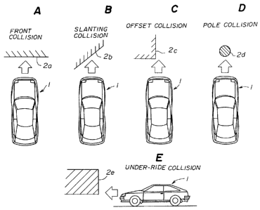
Now, description will be given of collision
modes with reference to Fig.lA to Fig.lE. Fig.lA shows
a front collision where an automobile 1 collides with
an object 2a having a surface normal to the automobile
direction of travel. Fig.lB shows a slanting collision
where the automobile 1 collides with an object Zb
having a surface at an angle to the automobile
direction of travel. Fig.lC shows an offset collision
where the automobile 1 collides with an object 2c
offset from the automobile 1. Fig.lD shows a pole
collision where the automobile 1 collides with a
cylindrical object 2d such as a pole. Fig.le shows an
under-ride collision where the automobile 1 collides
with an object 2e positioned above the front bumper of
the automobile 1.
As described above, there are various modes
of collision. Accordingly, an acceleration signal
output from the acceleration sensor varies depending on
the mode of collision. The conventional air bag
control system mentioned above has a problem in that
although a determination of the pole collision and the
light collision can be performed, other collision modes
cannot be recognized.
If the collision mode cannot be recognized,
3 there is a possibility that a driving signal is sent
from the air bag control system to the air bag driving
mechanism when it is not needed. Additionally, there
is a possibility that the air bag is not inflated at an
appropriate timing because a driving signal is not sent
at to the air bag driving mechanism at the timing when
it is needed.
'- 20898a ~
-- 5 --
1 By the structure of the conventional air bag
control system, only two collision modes can be
recognized by a single acceleration sensor.
Accordingly, when recognizing all of the above
mentioned collision modes, a plurality of sensors are
needed. However, increasing the number of sensors
results in an increase of manufacturing cost.
Additionally, both hardware and software of a computer
which processes signals supplied by each sensor become
complex, and thus the cost of the system is further
increased.
SUMMARY OF THE INVENTION
The present invention provides an improved
and useful air bag system which eliminates the above
mentioned disadvantages.
The present invention can also provide an air
bag system which can inflate an air bag at an
appropriate timing corresponding to the collision mode.
Also the present invention can provide an air
bag control system which can recognize a collision mode
by analyzing an acceleration signal from an
acceleration sensor, which signal shows a
characteristic property.
In order to achieve the above advantages, an
air bag system according to the present invention
comprises:
an air bag driving apparatus including an air
bag and means for inflating the air bag upon receipt of
an air bag driving signal; and
an air bag control system comprising,
a first acceleration sensor which detects the
acceleration of the body of an automobile in a
longitudinal direction and outputs a first acceleration
signal,
an acceleration level computing means,
~ ~89~ ~
1 coupled to the first acceleration sensor, for computing
the degree of acceleration and a longitudinal post-
collision speed by using the first acceleration signal,
a rate of change computing means, coupled to
the first acceleration sensor, for computing the rate
of change of the first acceleration signal and
detecting a predetermined characteristic of the rate of
change, and outputting a first result,
a first judging means, coupled -to the
acceleration level computing means and the rate of
change computing means, for judging an occurrence of a
collision of the automobile by using the degree of
acceleration, the longitudinal post-collision speed and
the first resultant data, and outputting a first
judgment result,
a second judging means, coupled to the
acceleration level computing means, for computing the
period of time during which the degree of acceleration
exceeds a predetermined value for a first predetermined
period of time and judging an occurrence of a collision
of the automobile by using the degree of acceleration,
the longitudinal post-collision speed, the rate of
change and the period of time, and outputting a second
judgment result, and
an air bag driving signal outputting means,
coupled to the first and the second judging means, for
determining the occurrence of a collision of the
automobile based on the first and the second judgment
result and outputting the air bag driving signal to the
air bag driving apparatus.
According to the present invention, the
presence of a collision is judged by using the degree
of an acceleration, a post-collision speed, a rate of
change of the acceleration and the period of time
during which the acceleration exceeding a predetermined
value. The judgment is effectively performed by a
plurality of judging means. Therefore,. the different
~ 2~g~ 7
1 modes of collision can be detected by a simple system
with high accuracy and the driving signal for the air
bag can be output at an appropriate timing.
Other features and advantages of the present
invention will become more apparent from the following
detailed description when read in conjunction with the
accompanying drawings.
DETAILED DESCRIPTION OF THE PREFERRED EMBODIMENTS
First, a description will be given of the
principle of the present invention with reference to
Fig.2. Fig.2 is a block diagram of a first principle
of an air bag control system according to the present
invention.
L'~
- 8 - 20 8 9 8 Q 7
1 The air bag control system according to the
present invention comprises a longitudinal acceleration
sensor A1, an acceleration level computing means A2, a
rate of change computing means A3, a first judging
means A4, a second judging means A5, and an air bag
driving signal outputting means A6. The longitudinal
acceleration sensor A1 detects the acceleration of an
automobile in the longitudinal direction and sends an
output signal G to the acceleration level computing
means A2 and the rate of change computing means A3.
The acceleration level computing means A2 computes an
acceleration value V based on the output data G and
sends the acceleration value V to the first and second
judging means A4 and A5. The rate of change computing
.~
- 15 means A3 detects the rate of change BP of the output G
~ and sends the rate of change BP to the first judging
- means A4. The first judging means judges whether or
not a collision occurs based on the acceleration value
V and the rate of change BP and sends the resultant
data to air bag driving signal outputting means A6.
The second judging means A5 computes a time T1, which
is the period of time during which the acceleration
value V exceeds a predetermined value, and judges
whether or not a collision occurs based on the time T1
and the acceleration value V and sends the resultant
- data to the air bag driving signal outputting means A6.
The air bag driving signal outputting means A6
determines whether~or not an inflation of the air bag
is needed based on the resultant data received from the
first and the second judging means, and then outputs an
air bag driving signal.
The rate of change BP of the output signal G
is one of parameters indicating a collision mode. For
-
9- 208~807
1 example, the rate of change BP shows a violent change
in the case of a front collision where the crushed
portion shows a bellows-like deformation. Accordingly,
it is possible to determine a type of a collision by
using the rate of change BP. It should be noted that
the acceleration value V is also used when determining
the occurrence of a collision by the first judging
means A4 so as to eliminate an unnecessary inflation of
the air bag because the rate of change BP may show a
violent change during driving on a rough load in which
case an inflation of the air bag is not needed.
On the other hand, a collision mode can also
be recognized by using the time Tl. For example, the
case of the slanting collision or the under-ride
collision where the crash of the automobile occurs for
a relatively long time without rapid deformation of the
automobile body, the acceleration value V remains at a
high value for certain period of time. Therefore, the
time Tl is considered one of the parameters indicating
the collision mode. It should be noted that the
acceleration value V is also used when determining the
occurrence of a collision by the second judging means
A5 so as to eliminate an unnecessary inflation of the
air bag because the time Tl may become long in a
situation where an inflation of the air bag is not
needed.
As mentioned above, the resultant data output
from the first and the second judging means reflects a
corresponding collision mode. Therefore, the air bag
driving signal outputting means A6 outputs an air bag
driving signal corresponding to the collision mode.
Fig.3 is a block diagram of a second
principle of the present invention in which a further
-- 10 --
2i~89807
1 feature is added to the first principle shown in Fig.2.
In Fig.3, those parts that are the same as ones shown
in Fig.2 are given the same reference numbers, and
descriptions thereof will be omitted.
The air bag control system according to the
second principle of the present invention includes a
transverse acceleration sensor A7, a transverse post-
collision speed computing means A8 and a third judging
means A9 in addition to the system shown in Fig.2.
The transverse acceleration sensor A7 detects
an acceleration in the transverse direction of an
automobile body and sends an output signal GY to the
transverse post-collision speed computing means A8.
The transverse post-collision speed computing means A8
computes a transverse post-collision speed VY based on
the output signal GY and send the transverse post-
collision speed data to the third judging means A9.
The third judging means A9 determines whether or not a
collision occurs based on the transverse post-collision
speed VY and the acceleration value V supplied by the
acceleration level computing means A2, and then sends
the resultant data to the air bag driving signal
outputting means A6. The air bag driving signal
outputting means A6 determines whether or not an
inflation of the air bag is needed based on the
resultant data received from the first, the second and
the third judging means, and then outputs an air bag
driving signal.
According to the second principle of the
present invention, a collision mode can be also
recognized by the transverse post-collision speed VY.
For example,in the case of the offset collision or the
slanting collision, an acceleration in the transverse
089807
1 direction is generated in addition to an acceleration
in the colliding direction. Accordingly, the
transverse post-collision speed VY is considered one of
the parameters indicating a collision mode. It should
be noted that, similar to the above mentioned judging
means, the acceleration value V is also used when
determining an occurrence of a collision by the third
judging means A8 so as to eliminate an unnecessary
inflation of the air bag.
As mentioned above, the resultant data output
from the first, the second and the third judging means
reflects a corresponding collision mode. Therefore,
the air bag driving signal outputting means A6 outputs
an air bag driving signal corresponding accurately to
the collision mode.
Next, a description will be given of an
embodiment of the present invention.
Fig.4 is a perspective view of an example of
an air bag system 10. The air bag system shown in
Fig.4 comprises an air bag driving apparatus 12
provided in the center portion of a steering wheel 11
and an air bag control system 13. The air bag control
system 13 generates an air bag driving signal for
operating the air bag driving apparatus in accordance
with an acceleration signal G supplied by acceleration
sensors 14 and 15.
The air bag control system 13 comprises, as
shown in Fig.5, a longitudinal acceleration sensor 14,
a transverse acceleration sensor 15, an analog/digital
(A/D) converter 16, and a central processing unit (CPU)
18. The longitudinal acceleration sensor 14 detects an
acceleration in the longitudinal direction indicated by
an arrow A in Fig.4 and outputs a longitudinal
- 12 -
2 0 ~ 7
1 acceleration signal G. The transverse acceleration
sensor 15 detects an acceleration in the transverse
direction indicated by an arrow B in Fig.4 and outputs
a transverse acceleration signal GY.
The acceleration signals G and GY output from
each acceleration sensor t4 and 15 are supplied to a
CPU 18 after being digitzed by respective A~ conventers
16 and 17. The CPU 18 is connected to a power source
circuit 20 which supplies electricity to the above
mentioned air bag driving apparatus. The air bag
driving apparatus 12 comprises an air bag, an ignition
agent, a gas generating agent and a propagation agent
provided in the center portion of the steering wheel
11. When the air bag driving signal is output from the
CPU 18, the ignition agent is ignited and the gas
generating agent generates an amount of gas via the
propagation agent and thus the air bag is inflated.
Next, a description will be given of a
relationship between the acceleration signals G and GY
and collision modes.
As explained with reference to Fig.1, there
are five principal modes, namely the front collision,
the slanting collision, the offset collision, the pole
collision and the under-ride collision. In this
embodiment. I~e following featurization of the
acceleration signals G and GY is performed in
accordance with the five collision modes.
Fig.6 is an illustration for explaining a
relationship between collision modes and phenomena
occurring in an automobile. The phenomena occurring in
an automobile are classified into four different
features, namely "side member buckling", "side member
bending", "deformation of weak portion" and "transverse
- 13 - 2~39807
1 movement". The "side member buckling" represents the
deformation of a side member of an automobile in a
bellows-like shape. The "side member's bending"
represents a deformation of a side member of an
automobile in a shape of a bent bar. The "deformation
of weak portion" represents a deformation of component
parts made of soft material such as a radiator, an
apron upper member or a front bumper. The "transverse
movement" represents a deformation of component parts
of an automobile in a transverse (left-right)
direction.
As mentioned above, each of the five
collision modes has one or more of the above four
features. An experiment has been performed in order to
investigate the output from the acceleration sensors
when the above four features occur by crushing an
automobile equipped with acceleration sensors, and the
following results have been obtained. It should be
noted that two acceleration sensors are used in order
to investigate accelerations in the longitudinal
direction (moving direction of the automobile) and in
the transverse direction (perpendicular to the moving
direction of the automobile).
Fig.7A is a graph showing an output from a
longitudinal acceleration sensor in a condition where a
buckling of side member occurs. As shown in the
figure, the acceleration G in the longitudinal
direction has a wave-like characteristic having
repeated high and low peaks. It is considered that the
wave-like characteristic of the acceleration G is a
result of the fluctuation of acceleration which occurs
at every small deformation as the buckling of side
member is deforming in a bellows-like shape.
, - 14 - 20 8 ~ 8~ 7
1 In the conditions where bending of a side
member or a deformation of a weak point occurs, the
acceleration G output from the longitudinal
acceleration sensor shows a characteristic which is
similar in both case. Fig.8A is a graph showing the
acceleration G output from the longitudinal
acceleration sensor in the conditions where bending of
side member or deformation of a weak point occurs. As
- shown in the figure, in the conditions where bending of
side member or a deformation of weak point occurs,
unlike a buckling of side member, the longitudinal
acceleration G shows a characteristic of gentle change.
This is because in the condition where a side member is
bent, the deforming process of the side member is not
rapidly progressing but rather taking a relatively long
time to be bent and thus the acceleration G shows a
gentle characteristic without fluctuation. In the case
of the deformation of a weak portion, the deformation
process takes a relatively long time, similar to the
bending of a side member, due to its elastic
deformation, and the acceleration G shows a gentle
characteristic without fluctuation.
Fig.9A is a graph showing the acceleration GY
output from the transverse acceleration sensor in the
condition where transverse movement of an automobile
occurs. In this condition, as shown in the figure,
positive and negative accelerations corresponding to
transverse movement of an automobile are generated.
As mentioned above, the phenomena occurring
to an automobile are classified into three kinds of
feature of acceleration characteristic. Accordingly,
by detecting these three features and outputting an air
bag driving signal based on the detected results, the
- 15 - ~ 2 0 8 Y ~ 0 7
air bag can be inflated at an appropriate timing for all
collision modes. In this embodiment, the CPU 18 detects the
above three features by using the acceleration signals G and
GY, and the air bag driving signal is output based on the
result of detection.
Next, a description will be given of a first
embodiment of a control operation of an air bag performed by
the CPU 18 with reference to Fig. 10 and Fig. 11.
A control operation process shown in Fig. 10 and
Fig. 11 is a routine executed in a very short time after an
occurrence of a collision which has been detected. The
control operation process is executed in real-time as the
time collision occurs is not predictable.
When the procedure is started, first, in step 100
(hereinafter "step" is abbreviated as "S"), the acceleration
G is read from the longitudinal acceleration sensor 14, and
a judging value H1 (described in the following) is cleared to
zero. In S102, a post-collision speed V1, a degree of
acceleration V2, a rate of change dG/dt and a scale of
collision BPl are computed by using the acceleration G.
These values are obtained by the following equations.
rt
V1 =¦ Gdt (1)
J t-TW1
V2 =~ Gdt (2)
J t-TW2
(dG/dt) = (F1 - F2) / K1 (3)
F1 = r Gdt (4)
J t-TW3
~ 2 ~ 8 ~ 8 U 7
- 16 -
t-TW3
F2 = Gdt (5)
t-2TW3
t0 in the above equations represents a time when
the routine shown in Fig. 10 and Fig. 11 is started. In the
above equation (1), TW1 is set to, for example, 150ms, and
thus the post-collision speed V1 represents an integral of
the acceleration G during the period of time of a collision
under normal conditions.
On the other hand, TW2 in the above equation (2)
is set to, for example, 10ms, and thus the degree of
acceleration V2 represents the integral of the acceleration G
during a short time. That is, V2 represents a level of
acceleration in TW2. It should be noted that the value of V2
can be represented by the mean value of the past n number of
values of the acceleration G sampled every predetermined
perlod .
In this embodiment, the post-collision speed Vl and
the degree of acceleration V2 are computed separately so that
unnecessary inflation of the air bag is prevented such as in
the case of a light collision where the degree of
acceleration V2 is very low or in the case of driving on a
rough road where the post-collision speed V1 is very low.
The scale of collision BP1 is represented by a
frequency when the rate of change dG/dt of the acceleration
G exceeds a predetermined threshold value GTH1 in a period
of time from the time (t-TW1) to the time t. The rate of
change dG/dt is obtained by the above equation (3). F1 in
the equation (3) is the value obtained by the equation (4).
F2 is the value obtained by equation (5). In each equation,
TW3, which is a predetermined period of time, is set to, for
example, 5ms. Accordingly, the value obtained by
- 17 - 2089~07
1 equation (4) is the acceleration G for the last 5ms
before starting of the routine, and the value obtained
by equation (5) is the acceleration obtained for the
period of time from lOms before the start of the
routine to 5ms before the start of the routine. In
this embodiment, as indicated by equation (3), the rate
of change is represented by the difference between the
post-collision speeds Fl and F2 divided by a constant
Kl (for example, Kl is set to 0.2).
Fig.7B is a graph showing the rate of change
dG/dt of longitudinal acceleration G in the condition
where buckling of a side member occurs. Since a side
member is deformed in a bellows-like shape in a
collision where buckling of a side member occurs, the
acceleration G shows a wave-like fluctuation. Due to
this, the rate of change dG/dt of the longitudinal
acceleration G, which is a differential value of the
longitudinal acceleration G shows a large fluctuation.
The harder the collision, the greater the number of
occurrence of buckling. In other words, larger the
fluctuation of the rate of change, the harder the
collision. Accordingly, the severity of a collision
can be quantitatively represented by means of counting
the number of peaks in the wave form of the rate of
change dG/dt. The number of peaks is equal to the
number of buckles occurring in a side member.
In this embodiment, peaks exceeding the
predetermined threshold value GTHl are counted and the
resultant number represents the scale of collision BPl.
Fig.7C is a graph for explaining the scale of collision
BPl. In the condition shown in Fig.7B, since the
number of peaks exceeding the threshold value GTHl are
three, the scale of collision BPl is set as BPl= 3.
- 18 - 2089~07
1 After Vl, V2, dG/dt and BPl are computed in
S102, the routine proceeds to S104. In S104, it is
judged whether or not a fluctuation of an acceleration
in a longitudinal direction (refer to Fig.6) has been
occurring by judging whether or not the following
conditions are established.
First conditiOn ~----- BPl-BP
Second condition ~---- V12VTHl
Third condition ~----- V2>VTH2
Where BPTHl, VTHl and VTH2 are threshold
values for the necessity of inflation of an air bag
obtained by experiment.
In a judgment of the above first condition, it is
judged whether or not the scale of collision BPl is
greater than the predetermined threshold value BPTHl.
As mentioned above, the scale of collision BPl becomes
a large number in the case of a collision accompanied
by buckling of a side member. The CPU 18 judges that
the first condition is established when the scale of
collision BPl is greater than the threshold value
BPTHl.
Similarly, in judgments of the second and the
third conditions, it is judged whether or not the post-
collision speed Vl is greater than the threshold value
VTHl and whether or not the degree of acceleration is
greater than the threshold value VTH2. It can be
judged whether or not a collision accompanied by
buckling of a side member has occurred by observing
whether or not the first condition is established.
Since the scale of collision BPl is computed by using
the fluctuation of the acceleration G, BPl may become
large due to other conditions such as driving on a
rough road or a light collision where inflation of an
- 19 -
20~9807
1 air bag is not needed. This embodiment includes the
second and the third conditions in addition to the
first condition so as to eliminate undesired factors
other than the factors necessary for an inflation of an
air bag.
In S104, if it is judged that the first to
the third conditions are established, the routine
proceeds to S106. In S106, a predetermined weighting
value J11 is added to the judging value H1 and the
added value is set as the new judging value H1. On the
other hand, if it is judged that one of the first to
the third conditions is not established, the routine
proceeds to S108 where H1 is not changed and then
proceeds to the next step.
In S110, a time T1 (hereinafter called
collision time T1), which is a period of time when V2
exceeds the threshold value VTH3 during the
predetermined period of time TW1, is computed by using
V2 obtained by the process in S102.
Fig.8B is a graph showing an example of rate
of change of an acceleration V2 in a condition where
bending of a side member or deformation of a weak
portion occurs. As mentioned above, in a condition
where a crash of an automobile lasts for relatively
long time such as a front collision or an under-ride
collision, the acceleration V2 remains above a certain
constant value for a relatively long time.
Accordingly, the collision time T1 is considered one of
the parameters indicating the collision mode. In S110,
this collision time T1 is computed. It should be noted
that the collision time T1 corresponding to the
condition shown in Fig.8B is shown in Fig.8C. The
above collision time T1 is, for example, computed by
2~g9go7
1 means of a comparator and a timer included in the
CPU18.
In next S112, it is judged whether or not the
following four conditions are established. The process
in S112 is for judging whether or not a gentle
fluctuation of longitudinal acceleration occurs (refer
to Fig.6).
First condition ~ - T12TTHl
Second condition ~---- V12VTH4
Third condition ~----- V22VTH5
Fourth condition ~---- (dG/dt)2DGTHl
Where TTHl, VTH4, VTH5 and DGTHl are
threshold values for determining the necessity of
inflation of an air bag obtained by experiment.
In a judgment of the above first condition, it is
judged whether or not the collision time Tl computed in
the SllO is greater than the predetermined threshold
value TTHl. As mentioned above, the collision time Tl
becomes a large number in the case of a collision being
accompanied by bending of a side member or deformation
of a weak portion. The CPU 18 judges that the first
condition is established when the collision time Tl is
greater than the threshold value TTHl.
Similarly, in judgments of the second to the
fourth conditions, it is judged whether or not the
post-collision speed Vl is greater than the threshold
value VTH4, whether or not the degree of acceleration
is greater than the threshold value VTH5 and whether or
not the rate of change dG/dt is greater than the
threshold value DGTHl. It can be judged whether or not
a collision accompanied by bending of a side member or
deformation of a weak portion has occurred by observing
whether or not the first condition is established. As
- 21 - 2089807
1 explained with the process executed by S104 the
collision time T1 may become large due to other
conditions such as driving on a rough road or a light
collision where inflation of an air bag is not needed.
This embodiment includes the second to the fourth
conditions in addition to the first condition so as to
eliminate undesired factors other than the factors
necessary for inflation of an air bag.
In S112, if it is judged that the first to
the fourth conditions are established, the routine
proceeds to S114. In S114, a predetermined weighting
value J21 is added to judging value H1 and the added
value is set as the new judging value H1. If the test
performed by S104 was positive and J11 was added to H1
in S106, the judging value H1 renewed in S114 is set as
H1=J11+J21. On the other hand, if it is judged that
one of the first to the fourth conditions is not
established in the S112, the routine proceeds to S116
where H1 is not changed and then proceeds to the next
step.
In S118, the transverse acceleration GY
supplied by the transverse acceleration sensor 15 is
read. In the next step S120, the transverse post-
collision speed VY1 is computed by the following
equation by using the transverse acceleration GY.
~t
J (6)
It should be noted that the transverse post-
collision speed VY1 is represented by the absolute
value of the integrated value of the transverse
acceleration GY in the above equation (6) because
unlike the longitudinal acceleration, both the left and
2 ~ ~ ?) 8 0 7
1 right directions must be considered for the transverse
acceleration.
In the next step S122, it is judged whether
or not the following four conditions are established.
The tests in S122 is for judging whether or not a
fluctuation of transverse acceleration has occurred.
(refer to Fig.6).
First condition ~----- VY12VYTHl
Second condition ~---- V12VTH7
Third condition ~----- V22VTH8
Fourth condition ~---- (dG/dt)2DGTH2
Where VYTHl, VTH7, VTH8 and DGTH2 are
threshold values for determining the necessity of
inflation of an air bag obtained by experiment.
In a judgment of the above first condition, it is
judged whether or not the transverse post-collision
speed VYl computed in the S120 is greater than the
predetermined threshold value VYTHl. As explained with
reference to Fig.6, the transverse collision
acceleration GY is generated in the case of a collision
being an offset collision or a slanting collision.
Accordingly, the transverse post-collision speed VYl,
which is an integral of the transverse acceleration GY,
is considered one of the parameters indicating the
collision mode. The CPU 18 judges that the first
condition is established when the collision time Tl is
greater than the threshold value TTHl.
Similarly, in judgments of the second to the
fourth conditions, it is judged whether or not the
post-collision speed Vl is greater than the threshold
value VTH7, whether or not the degree of acceleration
V2 is greater than the threshold value VTH8 and whether
or not the rate of change dG/dt is greater than the
- 23 -
2089807
1 threshold value DGTH2. This, also, is for eliminating
undesired factors other than the factors necessary for
an inflation of an air bag. It should be noted that
Fig.9B is a graph showing the transverse post-collision
speed VY1 in a condition where the transverse
acceleration shows the fluctuation shown in Fig.9A.
In S122, if it is judged that the first to
the fourth conditions are established, the routine
proceeds to S124. In S124, a predetermined weighting
value J31 is added to judging value Hl and the added
value is set as the new judging value Hl. If the
processes executed by the S104 and S112 were positive
and J11 and J21 were added to H1, the judging value H
renewed in S124 is set as H1=J1l+J21+J31- On th
hand, if it is judged that one of the first to the
fourth conditions is not established in the S122, the
routine proceeds to S126 where Hl is not changed and
then proceeds to the next step.
In S128, it is judged whether or not the
judging value Hl is greater than a predetermined
threshold value HTHl. If it is judged that the Hl is
greater than HTH1 in S128, the routine proceeds to
S130. In S130, the CPU 18 sends the air bag driving
signal to the air bag driving apparatus 12 so as to
inflate the air bag.
In this embodiment, the air bag driving
signal is output when the judging value H1 is greater
than the threshold value HTH1. The judging value H1 is
a value to which the weighting values, respectively
corresponding to the features of the output from the
acceleration senSors~ J11' J21 and J31 are add
weighting is applied because most actual collisions are
complex such that a plurality of features output from
- 24 - 2089~07
1 the acceleration sensors explained with reference to
Fig.6 are detected in one collision.
By outputting the air bag driving signal
based on the judgment performed by using properly
determined weighting values Jll' J21 and J31' the air
bag can be inflated at an appropriate timing and an
improved accuracy of operation of the air bag is
obtained.
Additionally, in this embodiment, the
collision can be accurately detected by having only two
acceleration sensors. Therefore, the number of sensors
and related processing circuits can be reduced compared
to the conventional system which recognizes the five
collision modes by using corresponding five kinds of
sensors, and thus manufacturing cost is reduced. It
should be noted that, as apparent from the above
description, this embodiment has a capability
equivalent to that of a collision detection system for
five collision modes.
Z0 Next, a description will be given of a second
embodiment of a control operation of an air bag
executed by the CPU 18 with reference to Fig.12. Since
the second embodiment of a control operation has many
processes in common with the first embodiment mentioned
above, a description will be given of mainly the
differences between the first and the second
embodiments.
When the routine shown in Fig.12 is started,
in S200, the acceleration G is read from the
longitudinal acceleration sensor 14. In the following
S202, a post-collision speed V1, a degree of
acceleration V2, a rate of change dG/dt of the
acceleration G and a scale of collision BM1 are
- 25 - 2089~7
1 computed by using the acceleration G. These values are
obtained by the above equations (1) to (5), and the
scale of collision is obtained by the following
equation.
~tl~
BM~ J(dG/dt)dt (7)
t~l
The scale of collision BMl is represented by
the area of the hatched portions shown in Fig.13A.
That is, BMl is represented by an integrated of the
rate of change dG/dt in the regions where the rate of
change dG/dt exceeds a predetermined threshold value
GTH2. In the example shown in Fig.13A, the region for
the integration is the time tol to tll, the time to2 to
tl2 and the time to3 to tl3. Therefore, the scale of
collision is represented by the sum of the integrated
values of the rate of change dG/dt for the above
regions. Fig.13B is a graph showing the scale of
collision in a condition where the rate of change shows
the characteristic shown in Fig.13A.
Now, the scale of collision BMl and the scale
of collision BPl of the first embodiment explained with
reference to Fig.7B and Fig.7C are compared. The scale
of collision BPl is, as shown in Fig.7b and Fig7C, a
counted value of the peaks of the rate of change dG/dt
that exceed the predetermined threshold value GTHl.
Each of the peaks is counted as one peak regardless of
its height. Therefore, the scale of collision BPl is
considered as not always accurately reflecting the
severity of a collision.
On the other hand, since the scale of
collision BMl obtained in this embodiment is an
integrated value of the rate of change dG/dt in a
208~07
1 region where the rate of change dG/dt exceeds a
predetermined threshold value GTH2, the scale of
collision BM1 sufficiently reflects the severity of a
collision. In the example shown in Fig.13A, BP1
becomes 3 as the rate of change dG/dt exceeds the
threshold value GTH2 three times. However, the form of
peaks exceeding the threshold value is not uniform in
its height as well as its width. For example, the area
of one peak indicated by an arrow A is smaller than
that of other peaks indicated by arrows B and C.
Fig.13B is a graph showing the change of the
scale of collision BM1 in a condition where the rate of
change dG/dt shows the fluctuation shown in Fig.13A.
As shown in the figure, the increase of the scale of
collision BM1 corresponding the peaks B and C is
greater than that of the peak A. Accordingly, the
scale of collision BM1 of this embodiment reflects the
scale of peaks (correspond to severity of a collision)
and that enables it to accurately detect severity of a
collision.
Returning to Fig.12, the description of the
control operation of an air bag is continued. After-
computing the post-collision speed V1, the degree of
acceleration V2, the rate of change dG/dt of the
acceleration G and the scale of collision BM1 in S202,
the routine proceeds to S204, and it is judged whether
or not the following conditions are established.
Similar to S104, the process in S204 is for judging
whether or not a fluctuation of longitudinal
acceleration has occurred (refer to Fig.6).
First condition ~----- BM1>BMTH1
Second condition ~---- V1>VTH1
Third condition ~----- V2>VTH2
~089~07
1 Where BMTHl, VTHl and VTH2 are threshold
values for determining the necessity of inflation of an
air bag obtained by experiment.
In a judgment of the above first condition, it is
judged whether or not the scale of collision BMl is
greater than the predetermined threshold value BMTHl.
As explained in the above, the scale of collision BM
is a value more accurately reflecting severity of a
collision compared to the scale of collision BPl of the
first embodiment. Accordingly, the accuracy of
judgment can be improved in the second embodiment, and
a high accuracy of timing for inflation of an air bag
is obtained. The second and the third conditions are
the same as that in the first embodiment, and a
description thereof will be omitted.
If it is judged that the first to the third
conditions are established in S204, the routine
proceeds to S216. In S216, the CPU 18 immediately
outputs an air bag driving signal to the air bag
driving apparatus 12. On the other hand, if it is
judged that at least one of the above three conditions
is not established, the routine proceeds to S206.
In S206, the collision time Tl is computed
and then the routine proceeds to S208. In S 208, it is
judged whether or not the following four conditions are
established. Similarly to S112, the tests in S208 is
for judging whether or not a gentle fluctuation of
longitudinal acceleration occurs (refer to Fig.6).
First condition ~----- Tl>TTHl
Second condition V12VTH4
Third condition ~----- V2>VTH5
Fourth condition ~---- (dG/dt)>DGTHl
Where TTHl, VTH4, VTH5 and DGTHl are
- 28 -
2089~07
1 threshold values for determining the necessity of
inflation of an air bag obtained by experiment.
In S208, if it is judged that the first to
the fourth conditions are established, the routine
proceeds to S216 and an air bag driving signal is
output from the CPU 18 to the air bag driving apparatus
12. On the other hand, if it is judged that at least
one of the first to the fourth conditions is not
established, the routine proceeds to S210.
10In S210, the transverse acceleration GY
supplied by the transverse acceleration sensor 15 is
read. In the next step S212, the transverse post-
collision speed VY2 is computed by the following
equation by using the transverse acceleration GY.
~l~t~ } (8)
It should be noted that "Max" in the above
equation means that VY2 is represented by the maximum
value of the integral of the transverse acceleration GY
in a predetermined period of time TW4, for example
30ms. As shown in Fig.9B, the transverse post-collision
speed VY1 is affected by an acceleration GY in a
negative direction that results in decrease of VY1 as
indicated by an arrow A in Fig.9B. However, by taking
the maximum value as in the equation (8), a fluctuation
of the transverse post-collision speed VY2 caused by a
negative acceleration can be eliminated. Accordingly,
the transverse post-collision speed VY2 shows a
properly stable characteristic which enables it to
match the other judging conditions.
After the transverse post-collision speed VY2
is computed in S212, the routine proceeds to S214 where
- 29 - 208~7
1 it is judged whether or not the following four
conditions are established. The tests in S214 is for
judging whether or not a fluctuation of transverse
acceleration has occurred. (refer to Fig.6).
First condition ~----- VY2>VYTH2
Second condition ~---- Vl>VTH7
Third condition ~----- V22VTH8
Fourth condition ~---- (dG/dt)>DGTH2
Where VYTH2, VTH7, VTH8 and DGTH2 are
threshold values for determining the necessity of
inflation of an air bag obtained by experiment.
In S214, if it is judged that the first to
the fourth conditions are established, the routine
proceeds to S216. In S216, an air bag driving signal
is immediately output from the CPU 18 to the air bag
driving apparatus 12. On the other hand, if it is
judged that at least one of the first to the fourth
conditions is not established, the routine returns to
S200 and then the execution of S200 to S214 will be
repeated.
In this embodiment, if a positive judgment is
made in either S204, S208 or S214, the routine directly
proceeds to S216 and an air bag driving signal is
output immediately. By this process, the number of
steps is reduced and a software program can be
simplified, which results in reduced processing time.
As is well known, the allowable time for inflating an
air bag is very short and the decision whether or not
to inflate the air bag must be made in an even shorter
time. Therefore, by simplifying the processing time of
a control operation of an air bag, an inflation of an
air bag can be performing in minimal time.
It should be noted that although the accuracy
- 30 -
2~8~07
1 of judgment for inflation of an air bag is considered
to be lowered in comparison to the first embodiment
mentioned above, the accuracy remains at an allowable
level for an actual use by appropriately setting the
scale of collision BM1, the transverse post-collision
speed VY2 and the threshold values used in S204, S208
and S214.
Next, a description will be given of a third
embodiment of a control operation of an air bag
executed by the CPU 18 with reference to Fig.14. Since
the third embodiment of a control operation has many
processes in common with the first embodiment mentioned
above, a description will be given of mainly the
differences between the first and the third
embodiments.
When the routine shown in Fig.14 is started,
in S300, the acceleration G is read from the
longitudinal acceleration sensor 14. In the following
S302, a post-collision speed V1, a degree of
acceleration V2, a rate of change dG/dt of the
acceleration G and a scale of collision BM2 are
computed by using the acceleration G. These values are
obtained by the above equations (1) to (5), and the
scale of collision BM2 is obtained by the following~5 equation.
tll
BM2 =;Il{(dG/dt) - GTH3~dt (9)
tDI
The scale of collision BM2 is represented by
the area of the hatched portions shown in Fig.15A.
That is, BM2 is represented by the sum of the areas of
peaks of the rate of change dG/dt exceeding the
threshold value GTH3. The scale of collision BM2 is
- 31 - 2089~7
1 considered to be a quantitative value of severity of a
collision that exceeds a predetermined value determined
by the threshold value GTH3. Accordingly, The scale of
collision BM2 reflects a feature of a collision further
than the scale of collision BPl of the first embodiment
and BMl of second embodiment and that enables it to
accurately judge whether or not a collision has
occurred. Fig.15B is a graph showing the scale of
collision BM2 in a condition where the rate of change~0 shows the characteristic shown in Fig.15A.
Returning to Fig.14, the description of the
control operation of an air bag is continued. After
computing the post-collision speed Vl, the degree of
acceleration V2, the rate of change dG/dt of the
acceleration G and the scale of collision BM2 in S302,
the routine proceeds to S304, and it is judged whether
or not the following conditions are established.
Similar to S104, the process in S304 is for judging
whether or not a fluctuation of longitudinal~0 acceleration has occurred (refer to Fig.6).
First condition ~----- BM22BMTH2
Second condition ~---- V12VTHl
Third condition ~----- V22VTH2
Where BMTHl, VTHl and VTH2 are threshold
values for determining the necessity of inflation of an
air bag obtained by experiment.
In a judgment of the above first condition, it is
judged whether or not the scale of collision BM2 is
greater than the predetermined threshold value BMTH2.
As explained in the above, the scale of collision BM2
is a value more accurately reflecting a feature of a
collision than the scale of collision BPl of the first
embodiment and the scale of collision BMl of the second
2089807
1 embodiment. Accordingly, the accuracy of judgment can
be further improved in the third embodiment. The
second and the third conditions are the same as that in
the first embodiment, and a description thereof will be
omitted.
If it is judged that all of the first to the
third conditions are established in S304, the routine
proceeds to S312. In S312, the CPU 18 immediately
outputs an air bag driving signal to the air bag
driving apparatus 12. On the other hand, if it is
judged that at least one of the above three conditions
is not established, the routine proceeds to S306.
In S306, the collision time T1 is computed
and then the routine proceeds to S308. In S308, it is
judged whether or not the following four conditions are
established. Similarly to S112, the tests in S308 are
for judging whether or not a gentle fluctuation of
longitudinal acceleration occurs (refer to Fig.6).
First condition ~----- T1>TTH1
Second condition ~---- V1>VTH4
Third condition ~----- V2>VTH5
Fourth condition ~---- (dG/dt)>DGTH1
Where TTH1, VTH4, VTH5 and DGTH1 are
threshold values for determining the necessity of
inflation of an air bag obtained by experiment.
In S208, if it is judged that the first to
the fourth conditions are established, the routine
proceeds to S312 and an air bag driving signal is
output from the CPU 18 to the air bag driving apparatus
12. On the other hand, if it is judged that at least
one of the first to the fourth conditions is not
established, the routine proceeds to S310.
In S310, it is judged whether or not the
2~8~D7
1 degree of acceleration V2 is greater than a
predetermined threshold value VTH9. The tests executed
by S310 are mainly for detecting the pole collision or
the offset collision where a rapid increase of the
longitudinal acceleration is generated.
. The slanting collision and the offset
collision can be recognized by not only observing the
transverse acceleration GY but also observing a gentle
fluctuation of longitudinal acceleration G (refer to
Fig.6). The purpose of the tests in S310 are to reduce
a load on S308 and S304. By performing this test, the
front collision and the pole collision can be separated
from other collision modes and thus objects of
decisions made by S304 and S308 can be focused on the
slanting collision, the offset collision and the under-
ride collision. Therefore, further processed data can
be used in the judgment process executed by S304 and
S308 and thus the air bag control system according to
this embodiment can be constructed by using only one
acceleration sensor.
If the judgment is positive in S310, the
routine proceeds to S312 and an air bag driving signal
is immediately output from the CPU 18 to the air bag
driving apparatus 12. On the other hand, if the
judgment in S310 is negative, the routine returns to
S300 and thus repeats the process from S300 to S310.
In this embodiment, similarly to the second
embodiment, if a positive judgment is made in either
S304, S308 or S310, the routine directly proceeds to
S312 and an air bag driving signal is output
immediately. By this process, the number of steps is
reduced and a software program can be simplified, which
results in reduced processing time, and thus an
- 34 -
2089807
1 inflation of air bag can be performed without delay.
Additionally, in this embodiment, only one
sensor, which is a longitudinal acceleration sensor 14,
is used to recognize the five collision modes shown in
Fig.1. Therefore, the number of sensors can be reduced
and thus manufacturing cost is reduced.
the present invention is not limited to the
specifically disclosed embodiments, and variations and
modifications may be made without departing from the
scope of the present invention.