Note: Descriptions are shown in the official language in which they were submitted.
2~91803
3416-5F
~a~G~ CAT~rD 8Y8T~X
Field of the Invention
This invention relates to a rapid ~YrhAngc catheter system.
Nore particularly, this invention relates to a rapid ~Y~hAnge
catheter system comprising one or more balloon dilatation
catheters and an ~y~hAnge facilitator consisting of an elongated
exchange member and a rigid shaft.
Bark~rol-n~ of Inv~ntion
In the utilization of catheters to diagnose and treat
various medical disorders, it is very often required that more
than one device be used during the procedure. Because
positioning of the catheter at the desired location may be
difficult, time con~lming, or critical or pose a high risk,
techniques have been developed that facilitate exchange of
catheter devices.
The most common te~hn;~l~ for catheter ~xchAnge employs a
very long guidewire called an ~Y~hAnge wire. In this technique
the exchange wire is placed within a central lumen of a catheter
that has been previously positioned within the body. To maintain
the desired position, the exchange wire is advanced while the
catheter is simultaneously withdrawn. Once the catheter is
completely out of the body, it is removed from the exchange wire.
2~sl~a3
~second catheter i5 then positioned over the ~yrh~nge wire, and,
once the catheter is completely on the exchange wire, it is then
advanced to the desired site in the body. This over-the-wire
terhni~e for catheter exchange is considerably time c~n~lm;ng,
and it requires at least two operators to effect the exchange.
In addition, the very long ~yrh~nge wire extends beyond the
sterile field, which adds to the risk of contamination during the
procedure.
U.S. Patent No. 4,762,129 to Bonzel and U.S. Patent No.
5,040,548 to Yock describe balloon angioplasty catheters that can
be exchanged over a standard length guidewire. These catheters
are called monorail catheters, and they are designed such that
only a relatively short segment of the distal end of the catheter
i8 advanced over the guidewire, i.e., the catheter has a lumen to
receive the guidewire that extends from the distal tip of the
catheter to a location proximal to the balloon. Since the length
of the guidewire used is only about half that of an ~Ych~nge
wire, the catheter exchange can be done more quickly, and a
single operator may do the exchange. However, since a much
shorter segment of the catheter is concentric to the guidewire,
the monorail-type catheters have ~;mini~h~d axial support for
tracking the guidewire ttrackability) and transmission of axial
or longitudinal forces (pushability).
In addition to the drawbacks cited above, both of the
catheter exchange techniques described above have two additional
20slsa3
sl~ortc i ngS - increased dlameter of the catheters to a~ te
the guidewire, and risk of vessel trauma resulting from repeated
catheter passages. In a number of applications, over-the-wire
catheters are too large to be placed at the desired location. In
these applications, smaller catheters, whose diameters have been
reduced by eliminating the guidewire lumen, have been required.
Exchange with these prior art systems consisted essentially of
starting over after the first catheter was removed. This is
often time consuming, and there is an increased risk of
, lications resulting from vessel trauma. U.S. Patent Nos.
4,944,740 and 4,976,689 addressed the trauma issue by providing
an outsr tubular sheath concentric to an inner catheter.
However, this system would have very limited application in small
blood vessels, as the system itself would occlude the blood
vessel and cause isrh~mic complications. ~oreover, the outer
tubular sheath must be used as a system with its inner catheter;
if another catheter or guidewire was used initially, this system
could not make the exchange.
209~8Q3
.
~hjects of the Invention
It is an object of this invention to provide an atraumatic
rapid ~Yrh~n~e catheter system.
It is also an object of this invention to provide a rapid
~Yrh~nse catheter system comprising an exchange member and a
pushing shaft.
It is a further object of this invention to provide a rapid
exchange catheter system comprising an exchange member, a pushing
shaft, an Pypln~hle sheath membrane, and a hemostasic manifold.
It is a yet further object of this invention to provide a
method for the rapid exchange of PYrh~n~e me_bers, such as
catheters, guidewires and other devices.
These and other objects of the invention will become more
apparent in the discussion below.
Brief Descri~tion of the Drawinrc
Figs. 1 and 2 each represent lateral, longitudinal views of
respective Pmho~ nts of the invention;
Fig. 3 represents a cross-sectional view of the Pmho~;r-nt
of Fig. l;
2 ~ D ~
~ Figs. 4, 5, and 6 represent additional ~Loss-scctional views
of ~ Ls of the invention;
Flg. 7 represents an additional : ~~ nt of the invention
with the sheath collapsed;
Fig. 8 represents the : '_';r L of Fig. 7 with the sheath
; and
Figs. 9 and 10 represent cross-sectional views of a further
_';~ L of the invention.
~etailed DescriPtion of the Invention
The rapid eYchAnge catheter system (RECS) of this invention
provides a very rapid, atraumatic means of exchanging one balloon
dilatation catheter or other device for another balloon
dilatation catheter or other device. The RECS is comprised of
(1) a distal ~Yrh~nge member, preferably radiopaque, and (2) a
rigid shaft or wire attached to the exchange member. Optionally
the RECS may also comprise (3) a membrane sheath, which is folded
around and attached along the length of the rigid shaft, and (4)
2 hemostatic manifold in fluid connection with the membrane
sheath.
The RECS is used by, first, placing the ~y~hAnge member over
the proximal portion of the shaft of a catheter, e.g., a balloon
dilatation (PT Q) catheter, or a guidewire or other device, that
is to be withdrawn from a patient. Then, the exchange member is
2~918~
~vanced distally along the shaft until the GYrhA"ge member is
positioned at the target site, i.e., adjacent to or across a
stenosis, by pushing the rigid wire. The catheter, guidewire, or
other device is withdrawn, and then, if a membrane sheath is
present, the sheath is unfolded by flushing through the
tic manifold.
Now, subsequent PTCA catheters, guidewires, or other
devices, for example, atherectomy catheters, laser catheters,
stents, angioscopic or ultrasound imaging catheters, infusion
catheters, perfusion catheters, or the like, may be passed
through the sheath to the target site.
Additional exchanges can be made as desired through the
sheath. Since such additional exchanges are made within the
sheath, the s"hsD~nt catheters and other devices that are
introduced do not rub against the intima of the arteries, as
happens with both over-the-wire and monorail ~Y~hlnge techniques.
The ~Y~hAng~c with the RECS are rapid and atraumatic, with the
possibility of endothelial denudation, plaque, and intimal
dissection minimized.
In addition to providing a rapid and atraumatic means for
exchanging catheters and other devices, the RECS of the invention
can also be used for subselective infusion and perfusion.
Subselective infusion of various phArm-cological agents directly
to a lesion, ~cpG~jAlly during a yr~ceduL~ may reduce
complications, minimize systemic side-effects, and improve the
2~91gO~
~ng-term outcome of the procedure. In the évent of an abrupt
closure during an angioplasty, the RECS can be rapidly deployed
to provide coronary perfusion. With the sheath in the collapsed,
folded position, the distal ~Y~hAnge member can act as a
temporary stent, providing passive perfusion. If n~c~s~ry~
blood or an oxygen-bearing fluid could be pumped through the
sheath for active perfusion.
With the ability to perfuse, the RECS can provide life-
saving capability not presently available in known exchange
systems. Patients can be stabilized, and the requirement of
surgical standby for PTCA could be reduced or eliminated. In
addition to significantly reducing the cost of a PTCA procedure,
the reduction or elimination of the surgical standby requirement
would facilitate increasing the number of PTCA procedures
performed each year.
The invention can perhaps be better understood by making
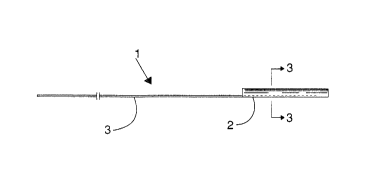
reference to the drawings. The ~ -;r ~ of the invention 1
shown in Fig. 1 comprises an ~Y~h~nge member 2 and a rigid shaft,
or corewire, 3 for advancing and/or retracting the exchange
member 2 to and/or from the target area in the vasculature (not
shown). The shaft 3 is preferably a wire. Exchange member 2
comprises a tubular member here; however, exchange member 2 can
be comprised of any structure that defines a lumen suitable for
~Y~hAnge purposes.
2091~3
~ Another ~ ':';r-nt of the invention 4 can be seen in Fig. 2,
wherein the exchange member is comprised of coil 5. Coil 5,
which is preferably helically wound, is either continuous with
shaft 6, that is, formed from the same wire, or is another wire
attached to shaft 6, preferably by solder, glue, a weld, or
similar affixation. In an alternate ~ L, coil 5 is butt
~oined to shaft 3.
Fig. 3 represents a cross-sectional view of exchange member
2, wherein it can be seen that shaft 3 is affixed to the interior
surface 7 of exchange member 2. The distal portion of shaft 3
within exchange member 2 preferably extends at least about 25~ of
the length of exchange member 2, more preferably about 50 to 100%
of the length of exchange member 2. It is within the scope of
the invention that shaft 3 may extend distally of ~Y~h~nge member
2 and have, preferably, a flexible and/or otherwise atraumatic
tip (not shown).
Shaft 3 may optionally, as shown in Fig. 4, be affixed to
the outer surface 8 of PYrh~nge member 2, in the same manner as
~;~cncsed for affixation to interior surface 7. It is also
within the scope of this invention that shaft 3 could reside
within the wall of exchange member 2.
As shown in Fig. 5, ~Yrhlnse member 2 may have a longitud-
inal slit 10 of sufficient width to enable the exchange member 2
to "snap" over a PTCA catheter, guidewire or other device.
Preferably the width of slit 10 would be from about 1 to 5 mm.
~ 2~91803
Also, as shown in Fig. 6, exchange member 2 may be discontinuous to
the extent that wall members 11, 12 overlap to provide an opening of
the same function as slit 10.
In a typical application of the invention described above, a
PTCA catheter is in position across or adjacent to a stenosis. The
exchange member 2 is positioned over the proximal end of the PTCA
catheter outside the body, and the exchange member 2 is advanced
over the PTCA catheter shaft to the stenosis. Then, the PTCA cath-
eter is withdrawn, Ieaving the exchange member 2 across the steno-
sis, where it can function as a temporary stent to permit perfusion
while additipnal therapy, for example, PTCA, atherectomy, insertion
of a permanént stent, CABG, or the like, is planned. Optionally
such an exchange can be done after the catheter/manifold hub of the
PTCA catheter has been removed.
A secondary device, for example, a second PTCA catheter, is
advanced adjacent to shaft 3, to the lesion. Then, the shaft 3 is
moved proximally to cause exchange member 2 to move proximally, ei-
ther adjacent to the target site or entirely from the body.
Rigid shaft 1 may be a conventional guidewire, preferably aspring guidewire, as is well known. Typical guidewires are shown
in U.S. Patents Nos. 4,757,827, 4,815,478, 4,813,434, 4,619,274,
4,554,929, 4,545,3g0,~ 4,538,622, 3,906,938, 3,973,556, ana 4,719,924.
In addition, shaft 3 could be solid or hollow, such as a hypotube,
2~918~3
w~ h an open distal end, to facilitate drug infusion. The
proximal end of the shaft would then preferably have a Luer hub.
m e shaft and exchange member of the invention may each
optionally have a lubricous coating or covering, such as any of
the known polysiloxane or TEFLON~ materials. Also, either, or
both, of the shaft and exchange member could be made of lubricous
material.
The ~y~h~nge member is, in general, made of r-'ic~lly
acceptable metal, for example, stainless steel, or rigid polymer,
such as a polyester selected from the group consisting of poly-
urethanes, polyethyleneterephthalate, polyethyleneterephthalate
glycol, and copolymers thereof, an olefin such as polyethylene or
a copolymer thereof, polyvinylchloride, or the like. The
exchange member could also be _ !~t of a material having
properties (e.g., shape, size, or flexibility), that change due
to hydration, temperature, or another factor. For example, a
shape memory alloy such as Nitinol may be used.
It is within the scope of the invention that the exchange
member may be ~ ch~hle from the shaft, to leave the exchange
member p~rr~n~ntly in place. Such detachability could either be
immediate or "on demand", where the shaft and exchange member
would be joined in such a way, or with such a r--h~nicr, that the
operator could manipulate the proximal end of the shaft to cause
the shaft and exchange member to separate. In the alternative,
the shaft and exchange member may be affixed by appropriate glue,
2091~3
f~ example, whose adhesive properties would lessen with time,
hydration, or t~ Lu~, such that after 24 to 48 hours the
shaft could be detached and withdrawn. For example, the adhesive
bonding properties of a hydrogel adhesive would ~iminich with
hydration.
In the . ~'i- L of the invention shown in Figs. 7 and 8,
the RECS 20 comprises a coil 21, preferably a rA~iopA~l~ coil,
and a rigid shaft or pushing wire 22. Positioned ecc~l~rically
or oonc~ ically, preferably eccentrically, around shaft 22 is a
flexible, collapsible sheath 23, shown collapsed in Fig. 7 and
expanded in Fig. 8. At the proximal end of sheath 23 is a
hemostatic manifold 24, including a valved infusion port 25 in
fluid communication with the interior of sheath 23.
In the alternate : ' 'i r ~ shown in cross-section in Figs.
9 and 10, sheath 32 is bonded or formed with shaft 30, which
defines lumen 31. Pushing wire 33 extends longitll~in~lly within
lumen 31.
Sheath 23 or 32 extends distally to at least the distal end
of pushing wire 22 or 33. Where exchange member 21 is instead a
cylindrical tubular member, such as exchange member 2, the sheath
23 or 32 can extend into and/or through said exchange member.
Sheath 23 or 32 ~acilitates the passage of a second PTCA
catheter, guidewire, or other ~Y~h~ng~Ahle device after the first
device is removed, and provides for atraumatic passage of these
2091~3
~her devices since the sheath 23 or 32 prevents contact of the
catheter or other device with the lining of the artery. A1BO~
the sheath can provide a means for subselective catheterization
for ~uL~oses such as tl) active perfusion of blood or oxygen-
bearing fluid; (2) distal/selective dye in;ection; or (3)
selective infusion of medications directly to the lesion site.
- ~he flexible sheath 23 or 32 is preferably bonded by
suitable means, such as heat-shrinking or adhesive, to the
pushing wire 22 or 33, respectively, either cont;nllollcly or at
discrete points longit~l~;nAlly along the pushing wire 22 or 33.
The proximal end of the sheath 23 or 32 is bonded by suitable
means, such as heat-shrinking or adhesive, to a manifold or hub,
and the pushing wire 22 or 33 may terminate at the manifold or
hub or extend proximally therethrough. Flexible sheath 23 or 32
and/or shaft 30 may each be single or multiple, such as double or
triple, lumen.
The preceding specific '_~ ntS are illustrative of the
practice of the invention. It is to be understood, however, that
other expedients known to those skilled in the art or disclosed
herein, may be employed without departing from the spirit of the
invention or the scope of the appended claims.
12