Note: Descriptions are shown in the official language in which they were submitted.
2 ~ 9
~092/0772~ pcr/&B91/nl9()6
L~TT~a BLAN~
TECHNICAL FIELD OF THE INVENTION
This invention relates to blanks for handwritten,typed, printed and/or photocopied letters
BACKGROUND
There is currently a trend ~owards saving raw
maeerials, and particularly timber based products such
as paper. Many letter~ and envelopes are now available
in recycled paper9 but the present invention is
intended to produce a further saving in raw materials.
Existing Air Mail leeter blanks which can be folded to
form their own envelopes have the advantage that they
save po~tage on the weight of an envelope. Such
airmail blanks are printed and cut to shape in the
manufacturing process in huge quan~ities. Whilst thiq
iq economical ~here large runs are concerned, thiR
proces3 is not 3uitable for-smaller print run~ where
the cost would be prohibi~iYe7 A blank of the standard
air mail~ letter shape ~ill not pass through the most
commonly used ~orm9 ~of prin~ing ~achine.
Reply cards whi.ch can be folded in two and secured by
peripheral adhesive are also kno~n, but these are
limited in size!. A standard A4 letter: embodying ~his
:
`
: :
: :
- . - .
, . .
W092/07725 2 ~ 9 ~ 12 ~ PC~/GB91/01906
principle would need to be made of heavy paper and
would be.inconvenient to handle.
An object of the present invention may be viewed as
being to provide a form of letter blank which is
capable of being printed in small quantities such as
would be typical for letterheadings in the domestic and
small busineqs sectors, and which is both easy to use
and results in a compact shape which is convenient for
posting.
.
SUMMARY OF THE INVENTION
The present invention proposes a letter blank which can
be printed by an offset litho process and having two
pairs of opposed edges, the blank including a
substantially rectangular letter portion and adhesively
coated marginal portions, and the arrangement being
such that the blank can be folded to form its own
envelope which can be secured by means of the marginal
portions.
: In one form of the letter blank the letter portion
includes tNo mutually perpendicular folds which divide
the letter portion ineo four subRtantially equal
rectangular portion~, and said marginal portions
comprise two adhesively coated flaps provided on
mutually adjacent edges of said blank. -.
:
In another form of the letter blank the marginal --
por~ions include user-removable pGrtions which are
defined by perforations such that, after printing, the
said portions can be removed to leave at least two
.
W092/07725 ~ 12 9 pcr/cBs1/o1~o
adhesively coated flaps for use in securing the blank
when folded to form its own envelope.
The term "user-removable" is intended to include
removal by the printer, although in most instances it
is envisaged that the removable portions will be
removed by the end user. The letter may more easily
pass through a typewriter or the like if the removable
portions are still in place. In addition, the term
"perforation" is intended to cover holes of any shape,
including slits.
In a further form of the blank there is a row of
perforations between the marginal portions and the
letter portion, and the blank includes three folds
which are substantially parallel to each other and to a
first pair of said opposed edges, said folds including
a first fold disposed substantially mid-way between
said first pair of edges, and two further folds, made
in opposite directions to the first fold, disposed
substantially equidistant either side of said first
fold.
In each form of the letter blank it is preferred that:
- a first pair of said edges includes a leading edge
which is such that it can stably abut a straight datum
line1 and an opposite trailing edge,
- a second pair of said edges has:
~ i) first mutually parallel straight edge
portions ~hich are substantially perpendicular to said
datum line and extend towards the leading edge for at
least lOmm from a point 35mm from the datum line,
(ii) second mutually parallel straight edge
portions which are substantially perpendicular to said
.
~ . :
:
~. - .
w092to7725 2 a 9 5 12 9 PC~/CB91/01906
datum line, are at least 8mm long, and lie within 35mm
of the trailin~ edge, and
(iii) at least one edge of said second pair
having a ~hird edge portion which is at least 35mm long
and is substantially perpendicular to said datum line
and extends between 90mm and 55mm from said leading
edge.
A blank meeting these criteria has the advantage that
it can be printed by certain litho print machines. The
first and second edge portions allou location by the
front and rear adjustable paper guides in an offset
litho machine such as the Rotaprint 30/95, and the
third edge portion allows for engagemen~ by the stroker
which feeds the sheets into the machine.
The trailing edge preferably includes a pair of
straight, mutually aligned four~h edge portions which
are each at least 30m~ long, span at least lOOmm
between their outer ends, and are substantially
parallel to said datum line. These portions can be
engaged by the weighted back stops of the machine. The
two fourth edge portions may in practice be provided by
a single straight edge portion with is at least lOOmm
long~
. .
BRIEF DESCRIPTION OF THE DRAWINGS
The invention is exemplified belo~ with reference to
the accompanyin~ drawings, in which:
~: i
Fi$~res 1 eo 3 show plan views of three
different forms of letter blank of the
~: :
.
.
~v092/077~5 2 ~ ~ 512 ~ PCT/GB91/01~06
invention,
Figure 4 is a front view of a fourth form of
letter blank of the invention,
Figure 5 is a rear view of the letter blank
of Fig. 4, and
Fi~re 6 is a perspective view of the letter
blank of Fig.s 4 and 5 in a partially folded
configuration.
~ETAILED DESCRIPTION OF THE DRAWINGS
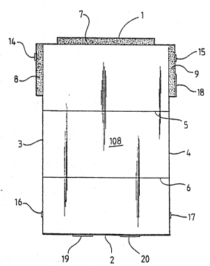
The illustrated letter blanks are substantially
rectangular having a leading edge 1, a parallel
trailing edge 2 and a pair of longer parallel side
edges 3 and 4. Each blank includes a central oblong
rectangular letter portion 108 surrounded by various
marginal edge portions, as described below. Although
it could be of any other desired size, the blank will
usually be of A4 ~ize (i.e~ about 297 mm by 210 mm).
In the blank of Fig. l, the letter portion 108 can be
folded into three equal portions by folding along two
crease line~ 5 and 6 which are parallel with the
leading edge l. The letter portion 108 is joined to a
gummed marginal flap 7 ~hich forms a straight leading
edge l and is of such a length that it can stably abut
a straight edge. The side edges 3 and 4 include two
further gummed marginal flaps 8 and 9 located between
the leading edge 1 and the first crease line 5.
W092/07725 ~0 9 ~ 12 9 pcr/cB~1/olso6
The blank of Fig. 2 has a straight leading edge 1 and
the letter portion 108 can be folded into four equal
portions along two mu~ually perpendicular crease lines
10 and 11. The trailing edge 2 includes a gummed
marginal flap 12 located bet~een crease line 11 and
side edge 3, and the side edge 3 has a further ~ummed
marginal flap 13 located betweerl the crease line 10 and
the trailing edge 2.
The blanks can thus be folded along the respective
crease lines to form their own envelopes which can be
secured by moistening ~he gummed flaps.
In both forms of the blank described above the flaps
could be separated from the letter portion lOô by a row
of perforations to facilitate opening of the letter.
The blank of Fig. 3 again has a straight leading edge l
and includes marginal portions 105, 106 and 107 which
extend alonlg the side, trailing and side edges 3, 2 and
4 respectively. The letter portion 108 is provided
with two crease lines 5 and 6 which extend parallel
with the top edge 1 and divide the letter portion into
three portions 111, 112 and 113, the bottom two
portions 112 and 113.
The bottom margin 106 forms a central flap 114 which is
joined to tbe le~ter portion 108 by a row of
perforaeions 117. The length of the flap 114 is
~slightly less than the width of the letter portion 108.
The side margins 105 and 107 include further flaps 120
and 121 and user-removable `side portions 122 and 123.
The flaps 120 and 121 are separated from the side
. .
V092/~772~ 2 a 9 5 ~ 2 9 P~T/G~91/01906
portions 122 and 123 by notches 126 and 127. These
side flaps 120 and 121 are joined to the bottom third
113 of the letter portion 108 by perforations 128 and
129. The removable portions 122 and 123 are each
joined to the top and middle thirds 111 and 112 of the
letter portion 108 by a row of per~orations or slits
130, 131 respectively.
The flaps 114, 120 and 121 are each provided with a
layer of adhesive.
The blanks can be fed through most typewriters or
printers used ~Jith word processors. The user can then
remove the side portions 122 and 123, ~hich are easily
separated fromm the letter portion 108. Longer slits
offer less resistance to removal than perforations in
the form of circular holes or shorter slits so that it
is preferred for the user-removable portions 122 and
123 to be secured to the letter portion 108
predominantly by longer slits whereas the flaps 114,
120 and 121 will be secured to the letter portion
predominantly by holes or slits of ~uch shorter length.
; The letter portion 108 can be folded along the crease
lines 5 and 6 to form its o~n envelope, which ean be
secured by moistening the gummed flaps 114, 120 and 121
and folding them along the perforations 117, 128 and
129 so that the flaps adhere to t~e letter portion 108.
When the letter is required to be opened the
perforations 117, 128 and 129 allow easy separation of
the flaps from the letter poreion 108.
It ~ill be appreciated that the shape and position of
,:
.
`
W092/0772S 2 0 9 512 9 PCT/GB91/01~h
the flaps and the arrangement of the slits and/or
perforations described above is purely illustrative.
The same principle could be used with any form of
letter which can be folded to form its own envelope
which can be secured by two or more flaps. For
example, the letter portion 8 could be divided into
four substantially equal square or oblong rectangular
portions by two mutually perpendicular creases, and two
adjacent edges of the letter portion are provided with
two flaps for securing the letter as its own envelope.
In each of the blanks of Fig.s 1 to 3 the f~aps ar~d the
corresponding areas of the letter portion could be
coated with pressure-sensitive or other adhesives.
The blank of Fig.s 4 to 6 has a straight leading edge 1
and includes a continuous marginal edge portion 205
which completely surrounds the letter portion 108. The
blank is provided with three crease lines 209, 210 and
211, which extend parallel with the top edge 1 and
divide the blank into four portions 212-215, the top
and bottom portions 212 and 215 being of equal size and
the two centre portions 213 and 214 being of equal size
but shorter than the other two. The centre crease 210
is made in the opposite direction to the other two
crea3es 209 and 211 so that when the blank is folded as
shown in Fig. 63 the t~o middle portions 213 and 214
are sandwiched between the top and bottom portions ~12
and 215 in the manner of a W. The front surface of the
blank i9 thus completely enclosed.
Referring back to Fig. 4, the edge portion 205 is
joined to the letter portion 108 by a row of
perforations 216. On the front surface of the blank
. , , , .. - ~ - - ., , . :
-. .: .. .. . . .
. . . . .: . . ~ .. -
- ... .. -. . . .. - .. . ~. , - . . .
,, . . .. , - . . : : :
W092/07725 2 Q ~ ~ 1 2 9 Pcr/GB~ 9o6
the edge portion 205 is provided with areas 218 of
pressure sensitive adhesive. The front adhesive layer
218 is arranged in two areas around the top and bottom
portions 212 and 215 of the blank such as to adhere
them together when the blank is folded as shown in Fig.
6. On the opposite rear surface of the blank (Fig. 5)
the edge portion 205 bordering both sides of the centre
regions 213 and 214 is provided with two further layers
219 and 220 of pressure sensitive adhesive. These
layers 219 and 220 are arranged so as to adhere
together the two centre portions 213 and 214 when the
blank is folded. Since the adhesive areas 218, 219 and
220 adhere only to themselves, not to the paper,
similar letter blanks can be stacked without adhering
to each other.
.~gain, the blank can be fed throu~h most typewriters or
printers. The user can then fold the blank along the
crease lines 29, 210 and 211 to form its own envelope,
which is secured by the adhesive layers.
Instead of using pressure-sensitive adhesive the edge
portion 205 could be coated with various adhesives
including water-soluble adhesive.
When the letter is required to be open~d the
perforations 216 allow easy separation of the
adhesively secured edge portion 205 from the letter
portion 108, which can then be opened out and read as a
normal letter.
It will be appreciated that the position of ths
adhesive areas 218 to 220 could be varied. For
example, the entire front surface of the edge portion
.. . , . . - .
:: . ~ :
. ~ . , , . : ~ -,
- , , . . -
: . . . :
.
W092/0772~ 2 0 9 ~ 12 ~ PCr/GB9l/0l~06
205 could be adhesively coated.
In each of the above-described embodiments, it will be
noted that ii the letter is sent through the post the
rear of the letter will be date franked, thereby
providing a useful permanent record of the posting
date.
In each form of blank described above, the side edges 3
and 4 have the following:
(i) First mutually parallel straight edge portions 14
and 15 which are substantially perpendicular to the
leading edge 1 and extend towards the leading edge for
at least lOmm from a point 35mm from the leading edge.
: (ii) Second mutually parallel straight edge portions
16 and 17 which are substantially perpendicular to the
leading edge, are at least 8mm long, and lie within
35mm of the trailing edge 2.
I
(iii) A third edge portion 1~ of the edge 4 which is
at least 35mm long and is substantially perpendicular
to the leading edge 1 and extends between 90mm and 55mm
from the leading edge.
In addition, the trailing edge includes a pair of
straight, mutually aligned fourth edge portions 19 and
20 which are each at least 30mm long, are separated by
40mm, and are substantially parallel to the leading
edge 1.
The iirst and second edge portions 14, 15 and 16, 17
permit location of the blank by the front and rear
:
.,
-
;: . , : ~ -, . . - , .,
.
., - ~ . ~ , . . , . .
W092/07725 2 ~ 12 9 Pcr/~B9l/ol9o6
adjustable paper guides in an offset litho machine such
as the Rotaprint 30/95. The third edge portion 18 can
be engaged by the stroker which feeds the sheets into
the machine. The fourth edge portions 19 and 20 are
engaged by the weighted back stops of the machine.
The blanks can thus be printed on by most, if not all,
of the commonly used forms of offset litho printing
machine.
Although the blanks of Fig. 3 will normally be printed
with the flaps 114, 120 and 121 at the bottom of the
letter they could also be printed with the flaps at the
top.
It will also be appreciated that although the blanks
have been shown as separate sheets they could also be
joined at the leading and trailing edges 1 and 2 to
form continuous stationery.
* * * * * * * *
.
.