Note: Descriptions are shown in the official language in which they were submitted.
~ ~ 9 5 S 1 ~
-
203-693
(1291 EPO/CAN)
A~VTT. DF.T,IVF.RY SYSTF~I
~CKGROUND OF THF. T~vFNTToN
1. F;eld of the Tnvention
This invention relates to a surgical delivery
apparatus, and in particular, to an apparatus for delivering
an anvil component to a remote location within a hollow organ
to effect the joining of hollow organ sections by circular
anastomosis.
2. Descri~tion of the Prior Art
Circular anastomosis is the surgical joining of
separate hollow organ sections so that the sections
intercommunicate. Typically, the anastomosis procedure
follows surgery in which a diseased or defective section of
hollow tissue is removed and the remaining end sections are
to be joined. In accordance with such procedures, the
operative tissue is exposed by making several extensive
incisions in the body cavity wall and folding the cut tissue
to provide access to the surgical site. The diseased section
of the organ is removed thereby leaving two separate end
sections of organ which are thereafter fastened by means of a
stapling instrument which drives a circular array of staples
through the end sections and simultaneously cores out any
overlapping tissue to free the tubular passages.
SUMM~RY OF THF T~VF~TION
CA 0209~91~ 1998-01-27
The present invention provides a surgical apparatus for
delivering an anvil component to a targeted section of a
tubular organ so that anastomosis of two separated organ
sections may be achieved using minimally invasive surgical
techniques.
In accordance with an embodiment of the present invention
there is provided a surgical stapling apparatus having a
delivery system for an anvil component of an anvil assembly
including an elongated delivery member, mounting means for
releasably mounting an anvil component at the distal end of the
member, and releasing means for releasing the anvil component
from the mounting means; and comprising an anvil assembly
detachably mountable to a distal end of the member, the anvil
assembly having an anvil rod having a proximal end portion
having a longitudinal axis, and a distal end portion configured
to receive a substantially circular anvil head, the anvil rod
distal end portion being pivotally secured to the anvil rod
proximal portion, wherein the anvil rod distal end portion is
pivotable from a first position to a second position relative
to the longitudinal axis of the anvil rod proximal end portion.
In accordance with another embodiment of the present
invention there is provided a surgical apparatus comprising a
delivery system for an anvil component of an anvil assembly
including an elongated delivery member, mounting means for
releasably mounting an anvil component at the distal end of the
member, and releasing means for releasing the anvil component
from the mounting means; and an anvil assembly adapted for use
with an apparatus for performing a circular anastomosis, the
anvil assembly comprising an anvil rod having proximal and
distal end portions and a substantially circular anvil head
mounted to the distal end portion of the anvil rod, the anvil
head having a generally flat staple forming surface and being
pivotally secured to the anvil rod proximal end portion,
wherein the anvil rod distal end portion is pivotable from a
CA 0209~91~ 1998-01-27
first position, wherein the staple forming surface of the anvil
head is in general perpendicular alignment with a longitudinal
axis defined by the anvil rod proximal end portion, to a second
position, wherein the staple forming surface of the anvil head
is angularly displaced by about 90~ from the first position.
In accordance with a yet another embodiment of the present
invention there is provided a surgical apparatus comprising a
delivery system for an anvil component of an anvil assembly
including an elongated delivery member, mounting means for
releasably mounting an anvil component at the distal end of the
member, and releasing means for releasing the anvil component
from the mounting means; and having an anvil assembly for a
circular stapling instrument, the anvil assembly having a
generally circular anvil head and an anvil rod having proximal
and distal end portions, the anvil head being mounted to a
distal end of the anvil rod distal end portion, and comprising
a pivot pin for pivotably mounting a distal end of the anvil
rod proximal end portion to a proximal end of the anvil rod
distal end portion, wherein the anvil head and anvil rod distal
end portion are pivotable about the pivot pin and pivotable
relative to the anvil rod proximal end portion.
Yet another embodiment of the present invention provides
a surgical stapling apparatus comprising a delivery system for
an anvil component of an anvil assembly including an elongated
delivery member, mounting means for releasably mounting an
anvil component at the distal end of the member, and releasing
means for releasing the anvil component from the mounting
means; and having an elongate shaft, a handle assembly
connected to a proximal end of the elongate shaft, a fastener
retainer connected to a distal end of the elongate shaft, the
fastener retainer having a circular array of fasteners, and an
anvil assembly detachably mountable to a distal end of the
apparatus, the anvil assembly having an anvil rod, the anvil
- 2a -
CA 0209~91~ 1998-01-27
rod having proximal and distal end portions and a longitudinal
axis, and a substantially circular anvil head mounted to the
distal end of the anvil rod, the anvil head having a generally
flat staple forming surface in general perpendicular alignment
with the longitudinal axis defined by the anvil rod; and the
staple forming surface of the anvil head is pivotally secured
to the anvil rod proximal end portion, wherein the anvil rod
distal end portion is pivotable from a first position, wherein
the staple forming surface is in generally perpendicular
alignment with the longitudinal axis defined by the anvil rod,
to a second position, wherein the staple forming surface has
pivotably moved from the first position.
A still further embodiment of the present invention
provides a surgical stapling apparatus comprising an anvil
delivery system for delivering an anvil component within a
tubular organ section, comprising: an elongated delivery member
having a proximal end and a distal end and a longitudinal bore
extending therethrough; a hand grip portion disposed at the
proximal end of the elongated delivery member to facilitate
handling of the delivery system, the hand grip portion having
a longitudinal bore extending therethrough in axial alignment
with the longitudinal bore of the elongated delivery member;
a rod member slidably received within the longitudinal bore of
the elongated delivery member and the hand grip portion and
adapted to move towards the distal end of the elongated
delivery member, the rod member having a proximal end portion
extending beyond a proximal end of the hand grip portion; and
an anvil component releasably mounted at the distal end of the
elongated delivery member, the anvil component having an anvil
head and an anvil shaft, the anvil shaft inserted within the
bore of the elongated delivery member at the distal end thereof
to releasably mount the anvil component to the elongated
delivery member; wherein upon a distal force applied to the
proximal end portion of the rod member causes the rod member
CA 0209~91~ 1998-01-27
to be distally displaced such that a distal end of the rod
member engages the anvil shaft to effect release of the anvil
component from its engagement with the distal end of the
elongated delivery member; and further comprising an anvil
assembly detachably mountable to a distal end of the member,
the anvil assembly having an anvil rod having a proximal end
portion having a longitudinal axis, and a distal end portion
configured to receive a substantially circular anvil head, the
anvil rod distal end portion being pivotally secured to the
anvil rod proximal portion, wherein the anvil rod distal end
portion is pivotable from a first position to a second position
relative to the longitudinal axis of the anvil rod proximal end
portion.
In use, the distal end of the elongated delivery member
with mounted anvil component is inserted within the hollow
organ and advanced to a desired location in the tubular organ.
A distal force is applied to the proximal end portion of the
rod member, which causes the rod member to distally advance and
engage the anvil component to effect release of the anvil
component from its engagement with the elongated delivery
member to expel the anvil component within the desired organ
section.
The present invention also relates to a method for
performing circular anastomosis of first and second intestinal
sections using minimally invasive surgical techniques. The
method comprises providing an anvil delivery system, including
- 3a -
209lq~ s
an elongated delivery member having a proximal and a distal
end, mounting means for releasably mounting an anvil component
to the distal end of the elongated delivery member and
releasing means for releasing the anvil component from the
mounting means to expel the anvil component within the targeted
organ section. In accordance with the method, the distal end
of the elongated delivery member with mounted anvil component
is transanally inserted and advanced into the intestine until
the anvil component is disposed beyond a diseased tissue
section. The releasing means is thereafter actuated to release
the anvil
- 3b -
20359:~
-
component from the mounting means and to place the anvil
component within an intestinal section beyond the diseased
section. The anvil delivery system is then withdrawn from
the operative site.
Thereafter, a first and second side of the diseased
tissue section is isolated and the diseased section is
resected, preferably by laparoscopic means, leaving first and
second intestinal sections having first and second stapled
ends, respectively, with the anvil component disposed within
the second intestinal section. An opening is made in the
second stapled end of the second intestinal section so that
the anvil component may be grasped and exposed. An apparatus
for performing circular anastomosis of the first and second
intestinal sections is introduced transanally and advanced
into the first intestinal section until a distal end of the
apparatus engages the first stapled end. An opening is made
in the first stapled end to expose the staple holding
component of the apparatus. The anvil shaft is then mounted
within the staple holding component. This mounting
interposes the two ends of the intestinal sections between
the anvil component and the staple holding component. The
apparatus is fired and the anastomosis of the first and
second intestinal sections is completed. Thereafter, the
apparatus is removed from the body.
Generally stated, the present invention is directed
to an anvil assembly and associated delivery system, the
anvil assembly being adapted for use with an apparatus for
performing circular anastomosis. The anvil assembly
comprises an elongated anvil rod having proximal and distal
end portions and an anvil head detachably mounted to the
distal end portion of the anvil rod. The distal end portion
is pivotally mounted and is adapted to pivot from a first
~0~91~
operative position to a second non-operative position,
whereby at least one dimension of the anvil assembly in the
second non-operative position is effectively less than the
corresponding dimension in the first operative position.
In a preferred embodiment, the anvil assembly
comprises an elongated anvil rod having proximal and distal
end portions and an anvil head detachably mounted to the
distal end portion of the anvil rod. The distal end portion
is pivotal from a first operative position in general
alignment with a longitudinal axis defined by the anvil rod
to a second non-operative position angularly displaced
relative to the longitudinal axis. In the second non-
operative position, the anvil rod presents a less obtrusive
profile which, accordingly, facilitates advancement of the
anvil assembly through body tissue.
The distal end portion is pivotal with respect to
the longitudinal axis defined by the anvil rod through an
angle of up to about 90 . In particular, the distal end
portion is adapted to pivot up to about 90 with respect to
each side of the longitudinal axis, thereby providing full
pivotal articulation thereof of about 180-.
The distal end portion comprises a circumferential
mounting collar which is received within a circular aperture
formed within the anvil head to mount the anvil head to the
anvil rod. The mounting collar preferably comprises a
plurality of longitudinally extending external splines which
are engagable with cooperating longitudinally extending
internal splines formed within the anvil head to properly
align the anvil head with the anvil rod.
The anvil rod also comprises a plurality of
longitudinally extending external splines disposed
intermediate its proximal and distal end portions. The
20959 1 5
external splines are engageable with cooperating longitudinally
extending internal splines formed within a distal end of the
apparatus to properly align the anvil rod with the apparatus.
The anvil apparatus is adapted to be mounted to an
elongated delivery member which includes a mounting mechanism
for detachably mounting the anvil assembly on a distal end of
the elongated delivery member and releasing means for releasing
the anvil member from the mounting means.
The present invention is also directed to a surgical
apparatus for performing circular anastomosis of first and
second tissue sections. The apparatus comprises elongated
tubular means having a proximal and distal end, means for
firing a plurality of fasteners from the distal end of the
elongated tubular means and anvil means detachably mounted to
the distal end of the elongated tubular means. The anvil means
comprises an anvil rod having proximal and distal end portions
and an anvil head detachably mounted to the distal end potion
of the anvil rod. The distal end portion is pivotal from a
first operative position in general alignment with a
longitudinal axis defined by the anvil rod to a second non-
operative position angularly displaced relative to the
longitudinal axis. The anvil assembly defines an effective
cross-sectional area generally transverse to the longitudinal
axis. The effective cross-sectional area of the anvil assembly
in the second non-operative position is less than the effective
cross-sectional area of the anvil assembly in the first
operative position to
2 ~ 9 ~
facilitate introduction and advancement of the anvil assembly
through body tissue.
209.~91~
BRTFF DF~SCRTPTION OF THF DRAWI~GS
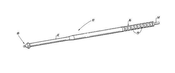
FIG. 1 iS a perspective view of the anvil delivery
system of the present invention;
FIG. 2 iS a side view of the delivery system of
FIG. 1 with a partial cutaway of the distal end, illustrating
the positioning of the anvil shaft of the anvil component and
tail portion within the elongated sheath member when the
apparatus is in the pre-fired condition;
FIG. 3 iS a perspective view of the delivery system
of FIG. 1 in the post-fired condition with the anvil
component expelled from the elongated sheath member;
FIG. 4 iS a perspective view of the delivery system
of FIG. 1 inserted transanally and extending through a
portion of the intestine;
FIG. 5 iS a perspective view of the delivery system
of FIG. 1 inserted through the intestine and in the post-
fired condition with the anvil component and tail portion
expelled from the delivery system;
FIG. 6 is a perspective view illustrating removal
of a diseased tissue section by a laparoscopic stapling
instrument;
FIG. 7 is a perspective view after application of
the laparoscopic stapling instrument, illustrating the formed
first and second intestinal sections;
FIG. 8 is a perspective view with a partial cut-
aways of the first intestinal section, illustrating
advancement of an apparatus for performing anastomosis and
exposure of the anvil shaft from the second intestinal
section;
FIG. 9 iS a perspective view with partial cutaways
of the first and second intestinal sections, illustrating the
209~91~
anvil shaft of the anvil component mounted within the staple
holding component;
FIG. 10 iS a perspective view of the anastomosis of
the first and second intestinal sections after firing of the
anastomosis apparatus;
FIG. 11 iS a perspective view illustrating an
alternative method for resection and removal of the diseased
tissue section in which the diseased section is to be removed
through the rectal opening;
FIG. 12 iS a perspective view after removal of the
diseased section through the rectal opening and application
of a laparoscopic stapling instrument to the first intestinal
section;
FIG. 13 iS a perspective view of a surgical stapler
apparatus for performing anastomosis of hollow organs of the
type contemplated by the present invention;
FIG. 14 iS a side plan view of an alternative
embodiment the detachable anvil rod constructed according to
the present invention illustrating the pivotal distal end
portion;
FIG. 15 iS a sectional view with parts separated of
the distal end portion and the remaining portion of the rod
of FIG. 14 illustrating the mounting components for pivotally
mounting the distal end portion;
FIG. 16 iS a side plan view of the detachable anvil
rod of FIG. 14 with mounted anvil head illustrating the
distal end portion of the rod in a generally aligned
operative position;
FIGS. 17A-17B are side plan views similar to the
view of FIG. 16 illustrating the distal end portion of the
209~9~ 5
anvil rod pivoted 90' with respect to each side of the
longitudinal axis defined by the anvil rod;
FIG. 18 is a side view of a delivery system used to
deliver the anvil rod to a desired predetermined location
within a tubular organ;
FIG. 19 is a perspective view of the intestinal
area of a patient illustrating the introduction of the
surgical apparatus of FIG. 13 prior to mounting of the anvil
rod of the present invention to the apparatus; and
FIG. 20 iS a perspective view similar to that of
FIG. 19 illustrating mounting of the anvil rod of the present
invention to the distal end of the surgical apparatus.
DF~CRIPTION OF THF p~FFF~RFn F~RoDIMF~Ts
Referring now to the drawings and, in particular,
to FIGS. 1-3, there is shown an anvil delivery system in
accordance with one embodiment of the present invention.
Anvil delivery system 10 includes an elongated sheath member
12 having longitudinal bore 13 (see FIG. 2) extending
therethrough, rod member 14, and hand grip member 16 disposed
at the proximal end portion of sheath member 12. Hand grip
member 16 also includes a longitudinal bore extending
therethrough in axial alignment with longitudinal bore 13 of
sheath member 12. In a preferred embodiment, hand grip
member 16 includes a grip enhancing means such as a plurality
of circumferential ribs l9 to facilitate grasping and
maneuvering of the delivery sys~em.
Anvil delivery system 10 expels anvil component 18
into a hollow tubular tissue section which is to be
subsequently attached to an adjacent tissue section by
circular anastomosis. Anvil component 18 includes anvil head
--10--
20959~
20 mounted on anvil shaft 22. Anvil shaft 22 is intended to
be mounted within staple holding component 62 tsee FIG. 8) of
a stapling apparatus. Anvil head 20 may include an annular
array of staple forming buckets to receive and bend staples
fired from staple holding component 62. It is to be noted
that the components of delivery system 10 can be modified to
accommodate a variety of sizes and types of anvils.
Rod member 14 is slidably received within
longitudinal bore 13 of sheath member 12 and the longitudinal
bore of hand grip member 16, and is adapted to move in a
distal direction relative to the remaining components in the
delivery system. In a preferred embodiment, proximal end
portion 17 of rod member 14 extends beyond the proximal end
of hand grip member 16 as best shown in FIGS. 1 and 2. When
a force is applied to proximal end portion 17, rod member 14
slides in a distal direction as shown by the arrow in FIG. 3.
This distal movement causes bearing surface 15 of rod member
14 to engage shaft 22 of anvil component 18 and to release
anvil component 18 from its engagement with elongated sheath
member 12, and to expel the component into a targeted tissue
section.
Anvil component 18 may be mounted to elongated
sheath member 12 by conventional means. In a preferred
embodiment and as best shown in FIG. 2, anvil shaft 22 is
inserted within the distal end of sheath member 12 to mount
the anvil component. Preferably, the diameter of shaft 22 is
slightly less than the inner diameter of the proximal end of
sheath member 12 such that the peripheral surface of shaft 22
frictionally engages the inner peripheral surface of sheath
member 12 to assist in retaining anvil component 18 within
the sheath member during insertion of the system within the
tubular organ.
2~ g ~ ~5
Delivery system 10 may range in length from about
60 cms to about 180 cms, however, any appropriate length may
be chosen depending upon the particular application. In a
preferred embodiment system 10 is straight, however, it is
within the scope of the present invention for system 10 to be
curved to facilitate placement of the instrument in
particular body structures and to reach remote or relatively
inaccessible operative sites. It is also possible for
delivery system 10 to be flexible. Preferably all components
of delivery system 10 are fabricated from polymeric
materials, which thereby reduces the cost of manufacture of
the system and makes it economically feasible to dispose the
system after use.
Further understanding of the significant aspects of
the delivery system of the present invention will become more
readily apparent by the following description of the use of
same. Referring now to FIGS. 4 - 10, the anvil delivery
system 10 in accordance with the present invention is shown
in a sequence of operation.
Referring initially to FIG. 4, the surgeon grasps
delivery system 10 by hand grip 16 and inserts the distal end
of the system with mounted anvil component 18 through the
rectal opening 30 and into colon or intestine 32. The system
10 is then advanced within intestine 32 until anvil head 20
extends slightly beyond diseased section 34 of the intestine.
-12-
2a9591 5
Referring now to FIG. 5, the delivery system is actuated
by the surgeon by depressing proximal end portion 17 of rod
member 14 (see FIGS. 1-3) to thereby effect distal movement of
the rod member and cause bearing surface 15 of the rod member
to engage the proximal end of shaft 22 and eject anvil
component 18 into intestine 32. It is to be appreciated that
after release from system 10, anvil component 18 is disposed
in a section of intestine beyond diseased section 34. At this
point in the procedure, delivery system 10 is removed from the
colon.
The diseased tissue section is then excised followed by
anastomosis of the adjacent severed tissue sections.
Preferably, the remaining operative procedures will be
performed using minimally invasive surgical techniques
including laparoscopic means and instrumentation. This is a
significant aspect of the present invention and is made
possible by the prior transanal placement of the anvil
component within the intestinal tissue. Such placement removes
the need for incising the abdominal cavity to introduce the
detached component to the operative site.
Referring now to FIG. 6, the preferred method for
resecting diseased section 34 is illustrated. Through
appropriate trocar sleeves, the surgeon applies a laparoscopic
stapler 50 to both sides of diseased section 34. A suitable
stapler for this purpose is described in commonly assigned U.S.
Patent No. 5,040,715 issued August 20, 1991. Each application
of the stapler places two triple staggered rows of staples 52
while a knife cuts therebetween. FIG. 6 illustrates the staple
rows after the application of stapler 50 to a section of the
intestine nearest rectal opening 30.
- 13 -
2~9~
FIG. 6 also shows stapler 50 being applied to a section of
the intestine beyond diseased section 34.
Referring now to FIG. 7, after application to both
sides of diseased section 34, stapler 50 will have created
two separated, closed end tissue sections 36, 40 having
stapled ends 38, 42, respectively. This application will
also have severed diseased section 34 from the remaining
intestinal tissue. In FIG. 7, diseased section 34 is already
removed from the operative site, preferably through one of
the trocar sleeves (not shown). At this point in the
procedure, anvil component 18 is positioned within tissue
section 40.
Alternative laparoscopic instruments and methods
may be incorporated to isolate diseased section 34 from the
remaining intestinal tissue and to remove section 34 from the
operative site. Referring to FIG. 11, the lower side of
diseased section 34 may be severed from the intestinal tissue
by, for example, a conventional scalpel. This step in the
procedure creates intestinal section 36 having open end 37.
Thereafter, stapling instrument 50 may be applied to the
upper side of section 34 to close off and completely sever
the diseased section from the intestine. Since the end of
tissue section 36 is not closed, open end 37 provides an
avenue to remove diseased section 34, i.e., removing the
diseased section through the rectal opening 30. After
removal, intestinal section 36 may be closed off as shown in
FIG. 12 by conventional means, such as, for example, with a
laparoscopic stapling instrument. Alternatively, tissue
section 36 may be closed off around the staple holding
component by a purse string suture.
It is also within the scope of the present
invention to close off the upper side of diseased section 34
20~91~
with a laparoscopic stapling instrument which fires a single
row of staples, and then sever the diseased section on its
upper side with a scalpel, laser or electrocautery device
which is applied through a trocar sleeve. Thereafter, a
similar cutting device may be used on the lower side of
section 34 and the completely severed diseased section
removed through end section 36 and out rectal opening 30 in
the same manner as previously described. Intestinal section
36 may then be closed off with the stapling instrument. It
is also possible to isolate diseased section 34 using a
scalpel on both sides of the diseased section and to leave
the ends of intestinal sections 36,40 open. Sections 36,40
may subsequently positioned for attachment by conventional
drawstring or purse string sutures.
Referring to Figs. 7-10 rejoining of the tissue
ends is accomplished by inserting an apparatus 60 for
performing circular surgical stapling of hollow tissue organs
through rectal opening 30 and into intestinal section 36.
Apparatus 60 includes staple holding component 62 with trocar
64 detachably mounted therewithin. Apparatus 60 may be any
known instrument that is adapted to be inserted transanally
to perform circular anastomosis of tissue sections. Examples
of such instruments are described in commonly assigned U.S.
Patent Nos. 4,304,236, 4,379,457, 4,573,468, 4,576,167,
4,603,693 and 4,646,745. Apparatus 60 is advanced into
section 36 such that staple holding component 62 approaches
stapled end 38 and trocar 64 contacts and penetrates the
stapled end to form an incision through end 38 to expose the
staple holding component. After the incision is formed in
stapled end 38, the surgeon, through an appropriate trocar
sleeve creates an opening with forceps or the like in stapled
end 42 of intestinal section 40 and probes within the opening
~0~9~5
to locate and grasp anvil shaft 22. Preferably, the anvil
assembly is provided with a tail 24 to assist in locating and
removing the anvil assembly. Tail 24 is a section of thread
or the like and is secured to shaft 22 prior to insertion of
the delivery system to facilitate withdrawal of the shaft
through the opening in stapled end 42. As shown, tail 24 is
removed from the opening and pulled away from end 42 by
forceps 70 until anvil shaft 22 becomes visible.
Referring to FIG. 8, trocar 64 is released from its
engagement with staple holding component 62 and removed from
the operative site through one of the trocar sleeves.
Thereafter, the surgeon grasps anvil shaft 22 with grasping
tool 80 and pulls the shaft until a portion of the shaft is
exposed. At this point in the procedure, intestinal sections
36 and 40 are ready to be joined together by circular
anastomosis. Intestinal sections 36, 40 are properly drawn
over and secured around staple holding component 62 and anvil
component 18, respectively, without maneuvering the tissue
around these components. This is a significant feature of
the present invention in that intestinal sections 36, 40 are
secured in position for attachment without requiring the use
of conventional drawstrings or purse string techniques to
tighten the tissue sections around their respective stapler
components.
Referring now to FIG. 9, through appropriate trocar
sleeves, intestinal sections 36,40 are approximated and anvil
shaft 22 is mounted within staple component 62. This mounting
properly interposes stapled ends 38, 42 of the intestinal
sections 36, 40 between staple holding component 62 and anvil
head 20, respectively. Thereafter, the stapling instrument
is fired to perform the anastomosis. The excess portion of
the ends of tissue portions are severed by the action of a
-16-
- 209591 5
knife edge incorporated in the anastomosis instrument. FIG.
10 illustrates the anastomosis of intestinal sections 36,40
after firing of the surgical apparatus. The surgeon thereafter
removes the instrument with attached anvil component from the
surgical site.
The present invention provides a novel device and method
for delivery of an anvil component within a tubular organ which
avoids the use of conventional surgery to expose the targeted
tissue portion. The device can be manufactured cost-
effectively and disposed of after use. The device makes it
possible to perform anastomosis of hollow tissue sections
entirely by laparoscopic techniques.
Although the present invention has been shown and
described in terms of a preferred embodiment, it will be
appreciated that various changes and other modifications are
contemplated within the spirit and scope of the present
invention as defined by the following claims.
Referring to FIG. 13, there is illustrated an apparatus
10' for stapling hollow tubular body organs as by circular
anastomosis of intestines, colons, or the like. The apparatus
may be utilized to attach two tubular body parts or one tubular
body part to a non-tubular body part by circular anastomosis
and may be adapted to attach the body parts with deformable
metallic staples or bio-absorbable two-part body tissue
fasteners.
Such apparatus 10' is disclosed and claimed in U.S. Patent
No. 5,119,983, issued June 9, 1992. This apparatus is a stap-
ler for anastomosis of hollow body organs such as intestines,
colons, etc. Other such devices are disclosed in the following
U.S. patents. U.S. Patent No. 4,304,236 issued December
209591 5
8, 1981; U.S. Patent ~o. 4,379,457, issued April 12, 1983;
U.S. Patent No. 4,573,468, issued March 4, 1986; U.S. Patent
No. 4,576,167, issued March 18, 1986; U.S. Patent No.
4,603,693, issued August 5, 1986; U.S. Patent No. 4,646,745,
issued March 3, 1987 and U.S. Patent No. 5,122,156, issued
June 16, 1992. As will be appreciated from a review of these
patents, such devices in some instances may also be manually
operated and are sometimes controlled from a location remote
from the point of manipulation.
Generally, apparatus 10' includes elongated shaft
12' and handle mechanism 14~ attached to a proximal end of
the elongated shaft. Handle mechanism 14~ includes actuating
handles 16~ and adjusting wing nut 18~. Fastener retainer
component 20~ is connected to the distal end of shaft 12' and
houses an annular array of staples therein. A staple firing
mechanism expels the staples from fastener retainer component
20'.
An anvil assembly 22~ is detachably mounted to the
distal end of elongated shaft 12' by a mounting mechanism
within the shaft which cooperatively engages the anvil
assembly. Anvil 22~ includes detachable anvil rod 24' with
attached anvil head 26'. Anvil head 26' includes staple
receiving buckets (not shown) for receiving and clinching the
staples expelled by the staple firing mechanism to thereby
join the adjacent tissue sections.
Referring now to FIG. 14, there is illustrated the
detachable anvil rod 24' constructed according to the present
invention. Anvil rod 24' is adapted to be used with
apparatus 10' and includes proximal end portion 28' which is
received within and engages the mounting mechanism within the
distal end of elongated shaft 12'. (FIG. 13) Proximal end
-18-
209~
portion 28~ includes a generally conical shaped mounting
portion 30' which is advantageously dimensioned to facilitate
entry within the distal end of apparatus 10' and which
further enables manipulation of rod 24' through body tissue.
Proximal end portion 28' also includes an annular recess 32'
which is correspondingly configured to be engaged by the
mounting mechanism within the distal end of elongated shaft
12~ of the apparatus.
A plurality of longitudinally extending external
splines 34' are disposed in the general midportion of anvil
rod 24~. Splines 34' engage correspondingly configured and
positioned longitudinal internal splines in the distal end of
elongated shaft 12~ during mounting of the rod to the
apparatus to ensure proper alignment of the rod with the
staple firing mechanism. Each external spline 34' has a
chamfered and sloped proximal end 36~. Chamfered ends 36~
engage the internal splines within elongated shaft 12' and
cause the rod to rotate slightly if the internal and external
splines are initially misaligned during mounting so as to
ensure proper mating between the two components.
Distal end portion 38~ of anvil rod 24~ includes an
anvil head mounting collar 40' for mounting anvil head 26~ to
the rod. Collar 40' includes a plurality of longitudinally
extending external splines 42' which engage with cooperating
longitudinally extending internal splines in the anvil head
26~ to properly align the staple-receiving buckets in the
anvil head with the staples in fastener retainer component
20~. A circumferential groove 44' is formed adjacent collar
40~ and is adapted to receive a U-shaped clamp which securely
retains the anvil head on the collar.
Distal end portion 38' of anvil rod 24~ is
pivotally mounted about pivoting pin 46' and is adapted to
-19 -
20~591~
pivot from a position in general alignment with the remainder
of rod 24~ through pivoted locations (shown by the arrows)
corresponding to plus or minus 90 degrees. As best shown in
FIG . 15, distal end portion 38~ includes a projecting member
48~ having a generally circular aperture 50' (shown in
phantom), which member 48' is received within a recess 52
defined between two correspondingly dimensioned and
positioned projection members 54~ extending from the main
portion of rod 24~. Preferably, a slight groove 56' is
formed in the main portion of rod adjacent recess 52' to
accommodate projecting member 48' during pivoting action of
distal end portion 38'. Projections 54' also include
apertures 58' (shown in phantom) which align with aperture
50' formed in projecting member 48' of distal end portion 38'
to receive pivoting pin 46' to effect the mounting. Other
alternative methods for mounting distal end portion 38' to
the main portion of rod 24' may be readily determined by one
skilled in the art.
Referring now to FIGS. 16, 17A and 17s, anvil rod
24~ is illustrated with anvil head 26' mounted on collar 40'
so as to illustrate the advantages of the novel pivoting
feature of distal end portion 38'. The pivoting feature of
distal end portion 38' facilitates introduction and
manipulation of anvil assembly 22' within tubular organ
tissue such as the colon, intestines, etc. by orienting anvil
head 26' in a manner which reduces the profile of the anvil
head and the anvil assembly as the assembly is being advanced
through the tubular organ. In particular, when distal end
portion 38' is in a generally aligned position as shown in
FIG. 16, which position corresponds to the orientation of a
conventional anvil assembly, the anvil assembly 22' presents
a relatively large cross-sectional dimension or profile which
-20-
209591~j
must pass through the tubular organ. Specifically, the
dimension or profile is equal to the diameter of the anvil
head, which in many instances, is greater than the
corresponding inner dimension of the tubular organ in which
it must pass. Consequently, anvil head 26' inherently engages
the inner wall of the tubular organ during manipulation and
advancement of the anvil assembly 22~ and, accordingly,
impedes such advancement within the tubular organ.
Referring now to FIGS. 17A and 17B, when distal end
portion 38' is pivoted to its transverse position by way of
the pivoting feature of the present invention, the effective
transverse cross-sectional dimension or profile of anvil
assembly 22~ is substantially reduced. In particular, since
anvil head 26~ is generally parallel to and flush with anvil
rod 24~ in this position, the effective transverse cross-
sectional dimension of assembly 22' is nearly one-half of the
corresponding dimension in the operative position of anvil
assembly shown in FIG. 16. It is to be appreciated that
distal end portion 38~ may be pivoted through a variety of
angles relative to the anvil rod and still present a cross-
sectional dimension or profile which is less than that of the
generally aligned position of the distal end portion shown in
FIG. 16.
In use, distal end portion 38' may be pivoted prior
to introduction of anvil assembly within the tubular organ or
may be initially inserted in a generally aligned position in
which it subsequently assumes a pivoted position during
advancement through the tubular organ due to engagement of
anvil head 26' with the inner wall of the tubular organ.
In performing intestinal surgery such as a
colonoscopy or a colectomy in which the surgery is followed
by anastomosis of hollow tubular organs, anvil assembly 22
-21-
2~9:1~
may be introduced into che hollow organ through a surgically
provided incision, or transanally, and advanced to a
predetermined location in the intestinal section so that the
anvil assembly may be subsequently mounted to a stapling
apparatus to complete the anastomosis.
Referring now to FIG. 18, there is illustrated an
apparatus which may be used to deliver anvil assembly 22~ of
the present invention to a predetermined desired location
within a tubular organ section. System 60' is particularly
adapted to deliver an anvil assembly transanally to a desired
portion in the colon and includes an elongated sheath member
62' having a longitudinal bore, a pusher rod 64' slidably
movable within the bore of the sheath member and hand grip
member 66'.
In use with the anvil assembly 22' of the present
invention, anvil rod 24' is inserted within the distal end of
sheath 62' to mount the assembly to the system. Thereafter,
distal end portion 38~ is pivoted to the position shown in
either FIGS. 17A or 17B to reduce the effective transverse
cross-sectional dimension of the anvil assembly 22'. The
delivery system is inserted transanally and advanced through
the colon to a predetermined desired location in the organ,
preferably beyond the diseased section of tissue. The
particular orientation of anvil head 24' facilitates
introduction and advancement of anvil assembly 22' within the
intestinal section. Thereafter, the delivery system is
actuated by depressing the proximal end section 64a' of
pusher rod 64', which extends beyond the proximal end of
sheath 62', to advance the pusher rod such that it engages
anvil rod 24~ and expels the anvil assembly 22' from delivery
system 60' and beyond the diseased tissue section. Once
anvil assembly 22~ is within the organ, the surgeon may
~0!359~
perform the desired surgery followed by anastomosis of the
hollow organ section.
FIGS. 19 and 20 illustrate the use of apparatus 10'
and detachable anvil rod 24~ in an anastomosis procedure to
effect joining of intestinal sections 66', 68'. Preferably,
the anastomosis procedure is performed using minimally
invasive surgical techniques including laparoscopic means and
instrumentation. At the point in the procedure shown in FIG.
19, a diseased intestinal section had been previously removed
preferably with a laparoscopic instrument applied to the
operative site through an appropriate trocar sleeve.
Elongated shaft 12' of apparatus 10' had been inserted
transanally into intestinal section 66'. Both intestinal
sections 66', 68' are also shown temporarily secured about
their respective components by conventional means such as a
purse string stitch.
In completing the anastomosis, the surgeon through
an appropriate trocar sleeve probes within the intestinal
section to grasp anvil rod 24', preferably with a grasping
instrument 70~ inserted within a cannula, and maneuvers rod
24' towards the distal end of elongated shaft 12'. Mounting
portion 30' of rod 24~ is then inserted within the distal end
of elongated shaft 12' of the apparatus, as shown in FIG. 20,
wherein the mounting mechanism within the distal end of the
shaft engages the rod to effect the mounting. Thereafter,
the anvil assembly and elongated shaft are approximated to
clamp the opposed end portions of tissue between anvil head
26~ and fastener retainer component 20~. Such approximation
will also appropriately orientate the anvil head 26~ with the
apparatus. The apparatus is fired to complete the
anastomosis.