Note: Descriptions are shown in the official language in which they were submitted.
~7~
INPRO~TED OPTICAI. READERS
Technical Field
The instant invention relates to devices for
reading optically encoded information of varying
densities, for example bar codes, and to associated
data input devices.
B~kqround Art
Optically encoded information, such as bar codes,
have become quite common. A bar code symbol consists
of a series of light and dark regions, typically in the
form of rectangles. The widths of the dark regions,
the bars, and/or the widths of the light spaces between
the bars indicates the encoded information. A
specified number and arrangement of these elements
represents a character. Standardized encoding schemes
specify the arrangements for each character, the
acceptable widths and spacings of tha elements the
number of characters a symbol may contain or whether
symbol length is variable, etc.
To decode a bar code symbol and extract a
legitimate message, a bar code reader scans the symbol
to produce an analog electrical signal representative
of the scanned symbol. A variety of scanning devi.ces
. .::,:: ~ ::: :.: : ::
~9~
736-005 2
are known. The scanner could be a wand type reader
including an emitter and a detector fixedly mounted in
the wand, in which case the user manually moves the
wand across the symbol. As the wand passes over the
bar code, the emitter and associated optics produce a
light spot which impacts on the code, and the detector
senses the light reflected back frorn the light spot
passing over each symibol of the code. Altexnatively,
an optical moving spot scanner scans a ~ight beam, such
as a laser beam, across the symbol; and a detector
senses reflected light ~rom the beam spot scanned
across the symbol. In each case, the detector produces
the analog scan signal representing the encoded
information.
A digitizer processes the analog signal to produce
a pulse signal where the widths and spacings between
the pulses correspond to the widths of the bars and the
spacings between the bars. The pulse signal from the
digitizer is applied to a decoder which first
determines the pulse widths and spacings of the signal
from the digitizer. The decoder then analyzes the
widths and spacings to find and decode a legitimate bar
code message. This includes analysis to recoqnize
legitimate characters and sequences, as defined by the
appropriate code standard.
Different bar codes have different information
densities and contain a different number of elements in
a given area representing different amounts of encoded
data. The denser the code, the smaller the elements
and spacings. Printing of the small size denser
sy~bols on an appropriate medium is exacting and thus
~ ~ ~ .' ' I , ' . ,
,, , , ' ;
2 ~
736-005 3
is more expensive than printing large size low
resolution symbols.
A bar code reader typically will have a specified
resolution, often expressed by the size of its
effective sensing spot. The resolution of the reader
is established by parameters of the emitter or the
detector, by lenses or apertures associated with either
the emitter or the detector, by the threshold level of
the digitizer, by programming in the decoder, or by a
combination of two or more of these elements.
In a laser beam scanner, the effective sensing
spot may correspond to the siæe of the beam at the
point it impinges on the bar code. In a wand using an
LED or the like, the spot size can be the illuminated
area, or the spot size can be that portion of the
i].luminated area from which the detector effectively
senses light reflections By whatever means the spot
size is set for a particular reader, the photodetector
will effectively average the light detected over the
area of the sensing spot. In one prior art example,
U.S. Patent No. 4,675,531 to Clark et al., an LED
illuminates the bar code and images the code onto a
photodetector. The aperture of the photodetector
dete D;nes the resolution or ~spot size.~ In the
Clarke et al. system the photodetector effectively
averages the light detected over the area of the
aperture.
A high resolution reader has a small spot size and
can decode high density symbols. The high resolutLon
reader, however, may have trouble accurately reading
low density symbols because of the lower quality
printing used for such symbols. This is particularly
:,; , ! ~
'''
: . : ~ '' . ' ' '
,: . :.: ' ,,,. i ::
'
,. ' ' ' :
3 ~ `~
736-005 4
true of symbols printed by a dot matrix tvpe printer.
The high resolution reader may actually sense dot
widths within a bar as individual bar slements. In
contrast, a low resolution reader detects an average
intensity using a large spot size and can decode low
density noisy symbols. However, a reader for
relatively noisy symbols of low density, such as the
dot matrix symbols, senses and averages such a wide
spot that two or more fine bars of a high resolution
symbol may be within the spot at the same time.
Consequently, a reader having a low resolution,
compatible with dot matrix symbols, can not accurately
read high density symbols. I'hus any reader having a
fixed resolution will be capable of reading bar codes
only within a limited range of corresponding symbol
densities.
Commonly assigned U.S. Patent Application Serial
No. 07/735,573 filed July 25, 1991, to Barkan et al.,
discloses a wand or scanner system for roading
optically encoded information having a wide range of
densities. The system includes either optical or
electronic means to derive two or more channels of data
from each scan pass of the wand or scanning beam over a
bar code. Each channel of data has a different
resolution, and the proposed system analyzes data from
the two channels to obtain a valid result over a wide
range of information densities. The optical and/or
electronic solutions proposed in that application,
however, are complex. The resulting system becomes
costly, and the wand or scanner becomes larger and
heavier due to the added components. A large, heavy
handheld unit causes fatigue and discomfor~ when a
", ,': . ~ ;
~ ' ~ , , .
2 ~ ~ ~ v~
736-005 5
user must hold and operate the unit for protracted
periods.
Clearly a need exists in the art for a bar code
reader which can be readily adapted to reading of bar
codes over a wide range of symbol densities without
adding undue complexity.
Another problem relates specifically to contact
wand type bar code readers. ~ypically, such wands
include an LED for emitting light to illuminate the bar
code and a lens for focusing the widely divergent light
from the LED onto the bar code. ~n many such wands,
the lens is part of the actual tip of the wand, and
consequently, the front surface of the lens contacts
the surface on which the bar code is formed during
scanning of the code symbols. Repeated use of the wand
causes wear and scratching of the front surface of the
lens. Such damage degrades the optical pxoperties of
the lens and reduces performance of the wand. ~s a
result, the lens must be periodically replaced.
Physical replacement of the lens, however, is time
consuming and costly.
Further problems arise from association of the
optical reader with other devices connected to a common
computer system. In actual use, the device for reading
optically encoded information typically connects to
some form of computer. Often a need exists for entry
of other data, in addition to that scanned by the
optical reader. For example, in an inventory system
using bar code readers the operator scans an item and
then enters the quantity of such items presently in
stock. Consequently, in most systems using optical
readers of the type discussed above, the system will
:, : : .:
.: . :
.. : ,'. ~:,: :. ' :
-, :.
~ ~ ~ r~ a
736-005 6
include additional data entry devices coupled to the
same computer. Separate data entry devices, however,
are often inconvenient to carry along in conjunction
with a portable optical reading device. Also, the use
of multiple data input devices requires use of several
of the option card slots of the computer and additional
physical wiring connections. Fur~hermore, multiple
input devices often create software problems directing
the multiple data input streams to a single application
program running on the computer.
To alleviate these problems, a number of optical
readers incorporate a keyboard and an alphanumeric
display to form an integrated data entry terminal.
These integrated terminals have included both contact
wand type bar code readers and pistol grip type moving
spot scanners. The data entry capabilities of such
integrated terminals, however, have been limited by the
nature of the keyboard and display.
A number of other types of data entry devices are
known, and in many applications provide more convenient
or user friendly da-ta entry operation than do
keyboards and alphanumeric displays. For example, a
mouse allows a computer operator to move a cursor to
point at an option illustrated on a display screen.
The operator then 'clicks a button on the mouse to
select the particular option. The mouse can also
provide graphics data input. U.S. Patent No. 4,906,843
to Jones et al. discloses a combination mouse and
optical scanner, but the optical scanner scans
characters or graphics data, not optically encoded
information such as bar codes. The user manually scans
.
. " , ..
.~; ': '
~7~
73~-005 7
characters by moving the mouse across the surface on
which the characters appear.
A number of other keyboardless, data entry
terminals have been proposed. IJ.S. Patent No.
4,972,496 to Sklarew, for example, discloses a terminal
device having a flat transparent input screen for
generating input information when an operator contacts
the screen with a stylus. A display screen mounted
below the input screen displays symbols and graphic
information drawn by the stylus. The operator inputs
information into the associated computer through pen
strokes essentially as if writing on a tablet with a
pen. U.S. Patent No. 4,916,441 to Gombrich discloses a
handheld terminal including a non-contact point source
type bar code reader and a touch sensitive display
screen.
From the above discussion it should be clear that
a need still exists to further develop various computer
input devices integrated with means to scan optically
encoded indicia which also provide convenient
operation.
DISCLOSURE O~ THE INVENTION
Obiectiv~s:
One objective of this invention is to provide a
bar code reader which is more convenient and efficient
to use when xeading encoded information over a wide
range of densities.
In contact wand type embodiments, it is a further
object of the invention to eliminate contact of the
optical elements of the wand with the surface scanned
`'
7 3 ~
736-005 8
in order to eliminate wear and damage to the optical
components.
Another objective of the present invention is to
provide an integrated data entry te D:inal for optically
reading encoded information and for convenient input of
other forms of data.
More specifically, one objective is to combine a
bar code reader with a display and touch sensitive type
data entry terminal, particularly where the bar code
reader is a moving spot scanner. Alternatively it is
an objective to incorporate a bar code reader, for
example, the moving spot scanner, into the stylus of a
graphic data input device. In another alternative, the
moving spot bar code scanner is incorporated into a
mouse type computer data entry device.
Sl1mmA~
In its simplest form, the reader for all densities
comprises a contact type wand including a laser light
emitter and a photodetector. The wand housing may be
cylindrical with a circular opening at one end. Light
from the emitter passes through the opening, reflects
off optically encoded information, passes back through
the opening and is sensed by the photodetector.
The laser light emitter will normally have some
established focusing parameter. As a result, the
emitted light beam will diverge at points farther away
from the beam focal point. The different diameter of
the beam at different distances can be used to
establish a different sensing spot size for the wand.
The different sensing spot sizes can then be used to
efficiently read optically encoded information of
.
.::
.
2 ~
736~005 9
different densities. To conveniently space the laser
emitter at different distances from the surface of the
encoded information, the invention therefore provides a
means for contacting a surface on which the optically
encoded information is formed. These means, typically
in the form of a spacer, selectively define at least
two different distances between the focal point of the
diverging beam of light and the optically encoded
information. Thus, the diverging beam of light will
have a specific diameter at its point of impact on the
optically encoded information for each of the two
distances set by the spacer means, and the specific
diameters will be different for each of the two
different distances.
lS In its simplest form, the spacer means includes of
the wand tip itself which contacts the encoded
information and defines a first distance. At the first
distance, the impact point is relatively close to the
focal point and to the laser light emitter, the beam
has diverged relatively little, and the resulting
sensing spot diameter is small. The small sensing spot
is effective in reading small bar code symbols, i.e.
information of relatively high density. To establish
at least one other distance, the spacer means further
includes a detachable spacer module. The detachable
spacer module can be mounted on the tip of the wand in
a manner concentric about the circular opening in the
tip. The detachable spacer module also has a tip for
contact with the encoded information through which a
second circular opening is formed. When attached to
the tip of the wand, the detachable spacer module
contacts the surface on which the code is formed during
, '' - ' ~ ' :
, '
736-005 10
scanning across the code. The attached spacer
effectively lengthens the wand structure and
specifically establishes a second longer distance. At
the longer distance, the impact point is relatively far
away from the beam focal point and from the laser light
emitter. At the impact point, the beam has diverged
further, producing a larger diameter sensing spot. The
large sensing spot is effective in reading larger and
noisier pxinted bar code symbols. These larger bar
code symbols correspond to optically encoded
information of relatively low density, such as bar
codes produced by a dot matrix printer.
~ clear sealing member may be placed at some point
within the housing between the opening and the emitter
and photodetector. The sealing member prevents dust
and dirt from entering. The sealing member is not
located at the tip of the wand. The tip of the wand
which contacts the surface of the optically encoded
information is just an open end of the cylinder.
Consequently, there is no optical element at -the tip
which ever contacts the encoded information, and
problems of damaging and replacing such an optical
element are eliminated.
The means for contacting the surface can ta~e a
Yariety of forms. For example, these means may
comprise a spacer adjustably mounted on the housing of
the wand. To change the distance, the spacer position
is adjusted. In one example, the spacer may slide on
or telescope with respect to the cylindrical wand
housing. When the spacer reaches a position
appropriate or reading a partic~lar density symbol,
the operator secures the spacer at that point by
,:
" , .
; ~ .
2~3~ t~
736-00S 11
tightening a set screw. Alternatively, the fore end
portion of the wand housing and the rear portion of the
spacer could have matching threads, in which case the
operator turns the spacer to change the position
S thereof and the overall length of the combined wand and
spacer structure.
The spacer means can also be adapted for use with
other ~ypes of optical readers. For example, another
disclosed embodiment provides a spacer mounted on a
pistol grip type moving spot laser scanner. The spacer
provides a desired long fixed spacing of the scanner
from the code which is particularly useful for scanning
dot matrix type low density codes.
The present invention also provides a number of
different forms of integrated data input terminal and
optical reader type devices. One integrated terminal
device has a generally gun shaped housing. The
elongaked body of the housing has a front region which
includes a flat display with touch sensitive data input
capabilities. A moving spot scanner within the housing
emits a beam of light through a window in an
intermediate body region extending between the fxon~
and rear regions of the housing. The beam is
transmitted along a path parallel to the upper surface
of the touch sensitive display in the front region of
the housing. On an upper surface of the rear region of
the housing, the terminal includes a keyboard. This
positioning of the keyboard allows an operator to
activate keys without interfering with emission of the
beam.
In another embodiment, the integrated terminal
includes a substantially flat housing having a front
.
2 ~ ~ 7
736-005 12
surface and a rear surface. Indicia-detection means
emit a light beam from the rear surface of the housing
for direction toward indicia to be read, and receive
light reflected from the indicia to produce electrical
signals representative of the indicia. Typically, the
indicia detection means comprise a moving spot laser
scanner and a photodetector. This embodiment further
includes a touch sensitive display disposed on the
front surface of the housing.
In a further embodiment, the invention comprises a
stylus for inpu~ of positional data to an electronic
digiti~er tablet which also incorporates elements of an
optical reader. In its broadest form the stylus would
include a light emitter, a photodetector and the
lS necessary electronics for operation as a stylus, all
contained with a stylus type housing. The stylus
electronics would correspond to the type of tablet
being used and can take a variety of forms. For
example, the stylus could apply a voltage to the tablet
to facilitate resistive detection of the contact point
on the surface of the digitizer tablet. ~lternatively,
the stylus could form a light pen, or provide a
capacitive contact, etc. In the illustrated
embodiments, the light emitter would comprise a moving
spot laser scanner module; but the emitter and
photodetector could correspond to the elements of a
contact wand type reader. The stylus can connect to
the tablet and/or an associated computer via a cable,
or the stylus can include a battery and a wireless
transmitter to send information signals to the
computer.
.. .
" . . .
736-005 13
In another aspect, the present invention
incorporates an optical scanner, for reading optically
encoded indicia, into a mouse type data input device.
This embodiment would include a mouse with relatively
standard electronics. The housing of the mouse also
contains a moving spot optical scanner module and
associated photodetector. The scanner emits a beam of
light from the bottom surface of the mouse housing, and
the photodetector detects the variable intensity of the
returning portion of the light reflected from an~
object scanned. The photodetector generates an
electrical analog signal indicative of the detected
variable light intensity. Typically, at least the
digitizer for converting analog signals from the
photodetector to a pulse signal would also be located
within the housing of the mouse. In a first version, a
user picks up the mouse and activates a third trigger
switch on the top surface of the housing to activate
the optical reader. A second version includes a
contact switch mounted in the lower surface of the
housing. The contact switch detects when the mouse is
resting on a surface and controls the device to provide
standard mouse type signals to ~he associated computer.
When the operator lifts the mouse off the surface,
however, the contact switch triggers operation of the
optical reader.
Typically, the light beam emitted by the scanners
of the present invention will be in the visible range
of the spectrum, for example red light. Consequently,
the beam scan across the code or indicia will be
visible to the operator. Also, the decode logic can
provide a "beep' signal as an audible output upon
'~ ' ' ,; ', '' '' ~"' ' ~ ".' '" ;' ' ' ,
' ' ~ ' ' '
2~7v~ ,?
736-005 14
detection of a valid read result. The visible beam and
the "beep'` signal provide feedback to the operator as
to the operation of the scanner.
Additional objects, advantages and novel features
of the invention will be set forth in part in the
description which follows, and in part will become
apparent to those skilled in the art upon examination
of the following or may be learned by practice of the
invention. The objects and advantages of the invention
may be realized and attained by means of the
instrumentalities and combinations particularly pointed
out in the appended claims.
Brief De~crip~ion of Drawin~s
Figures lA and lB illustrate in cross section a
first embodiment of the invention, in the form of a
wand type reader, with an adjustable spacer set at two
different positions to provide two different beam spot
sizes.
Figures 2A and 2B illustrate in cross section a
second embodiment of the invention, in the form of a
wand type reader, with a second adjustable spacer
design set at two different positions to provide two
different beam spot sizes.
Figures 3A, 3B and 3C illustrate in cross section
a third embodiment of the invention, in the form of a
wand type reader using detachable second spacers of
different lengths.
Figure ~ illustrates a further embodiment of the
invention, in the form of a pistol grlp type moving
spot scanner, with a spacer.
,
.
`. ' , ': . ~ . '; . ' .
:.~
2i~
736-005 15
Figure 5 illustrates a further embodiment of the
invention, in the form of a pistol grip type moving
spot scanner with a touch screen clisplay and input
device and a keyboard forming an integrated data input
terminal.
Figures 6A and 6B show another embodiment of an
lntegrated data input terminal having a moving spot
scanner and a touch screen display and input device.
Figure 7 illustrates in cross section an
embodiment of the invention, in the form of an
electronic stylus incorporating a moving spot optical
scanner.
Figure 8 shows an alternate embodiment of the
stylus incorporating a moving spot optical scanner.
Figure 9 shows an alternate embodiment o~ the
integrated stylus and scanner, similar to that of
FIgure 8, but using a wireless communication link to
the associated computer system.
Figures lOA is a cross sectional view and Figure
lOB is a top plan view of an embodiment of the
invention wherein the optical scanner is incorporated
into a mouse type input device.
Figure 11 illustrates an alternate embodiment of
the mouse type input de~ice with the incorporate
optical scanner.
Best Node for Carr~inq out the Invention
As shown in Figures lA and lB, the bar code wand 1
of the first embodiment includes a cylindrical housing
11 which contains a light emitter, such as a visible
light laser diode (VLD) 13. The VLD 13 emits light
which passes through an optical element, such as lens
" ~ , " ~ ,;,, "~'"', , , i '~'.~', ' -
~ 3 ~? 3
736-005 16
15. The lens 15 focuses the laser light to a point P.
The focused light passes through a transparent member
17 which serves to seal the wand against dust and
debris. The housing 11 also contains a light sensitive
photodetector 19, located behind the transparent
sealing member 17, for sensing light reflected back
from information scanned using the wand.
Since the wand uses a focused laser beam, no
aperture is needed to define the sensing spot.
Instead, the sensing spot of the laser wand corresponds
to the size of the area illuminated by the beam and the
diameter or spot size of the beam itself at the point
where the beam impacts on the surface being scanned.
As illustrated by comparison of Figures lA and lB, as
the emitted light passes beyond the focal point P, the
light diverges. At points close to the focal point,
the beam diameter wi.ll be small, whereas at points
further beyond the focal point the beam diameter will
be larger. Thus, for different distances from the
focal point, the beam will produce different size
sensing spots which will be effective for reading
different sizes and densities of symbols of optically
encoded information.
The wand also includes a spacer member 21. The
inside diameter of the distal end of the spacer 21 is
slightly larger than the outside diameter of the fore
end portion of the housing 11. Thus the spacer 21 can
be slideably mounted on the fore end portion of the
housing 11. When the spacer is in a desired position
for reading a particular density, an operator tightens
set screw 25 to secure the spacer in position. The
fore end of the spacer 21 tapers to a point through
. .: - : .
- : : . ,
u
736-005 17
which is formed aperture ~3. Light from the VLD
emerges from the aperture 23.
In use, an operator holds the wand in one hand and
places the tip of the wand against the surface S on
which is formed the encoded informati.on, e.g. the bar
code. To scan the information, the operator moves the
wand across the symbols while maintaining contact of
the tip of the spacer 21 with the surface S. secaus2
the light beam diverges, the beam spot sLze at the
point where the light impacts on the information
surface will be determined by the distance from the
focal point.
Comparison of Figure lA to Figure lB demonstrates
how repositioning of the spacer will produce different
beam spot diameters on the surface of the info.rmation
during scanning. In Figure lA, the spacer is mounted
relatively far forward on the fore end of the housing
11. When the tip of the spacer contacts the surface S,
the distance between the focal point P aind the surface
S is relatively long, and the beam spot is large. The
large beam spot would be appropriate for reading low
density encoded information, such as dot matrix printed
bar codes. In contrast, in Figure ls the operator has
telescoped the spacer back on the housing. When the
tip of the spacer contacts the surface S, the distance
between the focal point P and the surface S is
relatively short, and the beam spot is small. The
small beam spot would be appropriate for reading high
density encoded information, such as very small size
bar code symbols.
The invention of Figures lA and lB allows an
operator to adjust a single wand to read a range of
,' ' ' '.';. ' '' ', J ~ .` 1. .' ` ~ . ' '
' ' ' : :'
736-005 18
symbol densities. To change from a setting for one
density to a new setting for another densi~y, the
operator simply loosens set screw 25, moves the spacer
to a new position, tightens the set screw 25 and scans
the wand 1 across the optically encoded information.
If scanning is unsuccessful, the operator can repeat
this procedure a-t another setting until the scanning is
successful.
The second embodiment of the invention, using a
threaded spacer structure appears in Figures 2A and 2B.
Here, the bar code wand 1' includes a housing 11' which
contains a VID 13'. The VLD 13' emits light which
passes through the lens 15~ and is focused to a point
P'. The focused light passes through a transparent
member 17' which serves to seal the wand against dust
and debris. The housing 11' also contains a detector
19', located behind the transparent sealing member 17,
for sensing light reflected back from information
scanned using the wand.
The wand also includes a spacer member 21~. The
male threaded outer surface of the fore end portion of
housing 11' engages the female threaded distal end of
the spacer 21'. Thus, the spacer 21' can be screwed
onto the fore end portion of the housing 11~ until it
reaches a desired position for reading a particular
density. The fore end of the spacer 21' tapers to a
point through which is formed aperture 23'. Light from
the VLD and emerges from the aperture 23'.
Comparison of Figure 2A to Figure 2B demonstrates
how repositioning of the spacer in the second
embodiment will produce different beam spot diameters
on the surface of the information during scanning. In
.. ' ' ', . , :-
''; .' : ' . ' ~; ., ~
3 ~ ~
736-005 l9
Figure 2A, the spacer is threaded to a posltion
relatively far forward on the fore end of the housing
11'. When the tip of the spacer contacts the surface
S, the distance between the focal point P~ and the
surface S is relatively long, and the beam spot is
large. In contrast, in Figure 2B the operator has
turned the spacer 21' so that the threads position the
spacer relatively far back on the housing 11'. When
the tip of the spacer contacts the surface S, the
distance between the focal point P' and the sur~ace S
is relatively short, and the beam spot is small.
The invention of Figures 2A and 2s allows an
operator to adjust a single wand to read a range of
symbol densities. To change from a setting for one
density to a new setting for another density, the
operator simply turns the spacer 21' until it reaches a
new position, and scans the wand across encoded
information. If scanning is unsuccessful, the operator
can repeat this procedure at another spacer position
until the scanning is successful.
In the third and perhaps the simplest preferred
embodiment of the invention, shown in Figures 3A-3C,
the laser wand 101 has a structure similar to that of
the wand used in the earlier described embodiments.
For example, the cylindrical wand housing contains a
VLD~ a lens, a photodetector and a transparent sealing
member. In the third embodiment, however, the fore end
of the housing is designed for direct contact with the
surface S on which the bar code appears. The fore end
of the housing tapers, as shown at 121, to a circular
aperture 123. The VLD emits light which is focused by
the lens and passes through the transparent member to
, .
,
2 ~ ~ r
736~005 20
emerge through opening 123. The light will reflect
back off of the bar code or other optically encoded
information on the surface S, and the photodetector
will sense the reflected light.
When the tapered tip 121 of the wand 101 contacts
the surface S, during scanning across a code, the
distance between the focal point and the surface S is
relatively short. Consequently, the beam spot is
small, as shown in Figure 3A. The small beam spot
lO would be appropriate for reading high density encoded
information, such as very small size bar code symbols.
To increase the spot size, for example to read
lower density bar codes, the operator inserts the fore
end of the wand 101 into a spacer 221, as shown in
15 Figure 3B. The inside diameter of the distal end of
the spacer 221 is minimally larger than the outside
diameter of the fore end portion of the wand 101. This
produces a friction or pressure fit of the spacer 221
on the wand 101. The tension between the spacer and
20 the wand should be sufficient to retain the spacer in
place on the ~ip of the wand during scanning but still
allow an operator to manually attach and remove the
spacer from the wand.
The spacer 221 serves to lengthen the distance
25 between the focal point and the surface S. With the
spacer 221 mounted on the tip of wand 101, the operator
contacts the fore end of the spacer to the surface S
and scans the wand across the code. The increased
distance between the focal point and the surface S
30 causes the spot size of the beam at the point of impact
on the surface to increase. Figure 3B shows that the
beam at the point of impact wlll have a larger diameter
.
.. .:
2 ~ t~
736-005 21
than woul~ be the case without the spacer, as shown in
Figure 3A. The larger spot size of Figure 3B would be
suitable for reading of medium density bar code
symbols.
To further increase the spot si~e, to read
extremely low density bar codes such as those printed
by dot matrix printers, the operator inserts the fore
end of the wand 101 into another spacer 321, as shown
in Figure 3C. As with the spacer 221, the spacer 321
is designed to provide a friction or pressure fit of
the spacer 321 onto the tip of wand 101. This serves
to retain the spacer 321 in place on the tip of the
wand 101 but still allows an operator to manually
attach and remove the spacer 321 from the wand.
The spacer 321 includes a cylindrical extension on
the tip thereof which makes the spacer 321 longer than
the spacer 221. This extension can take virtually any
shape the designer chooses so long as it increase the
length of the spacer by a desired amount. Spacer 321
therefore provides a still longer distance between the
focal point and the surface S than did the wand 101
alone (Figure 3A) or the wand with the spacer 221
attached (Figure 3s). ~gain, the increased distance
between the focal point and the surface S serves ~o
increase the spot size of the beam at the point where
the diverging light beam impacts on the scanned surface
S. Comparing Figures 3A-3C, it should be clear that
the longer distance provided by spacer 321 produces the
largest spot size. With the spacer 221 mounted on the
tip of ~and 101, the operator contacts the fore end of
the spacer to the surface S and scans the wand across
the code, and during such scanning the larger spot size
,
.` ,' !
2 ~
736-005 22
would adapt the wand to effectively read low density
bar code symbols.
In use, an operator adds or changes spacers
whenever a scan is unsuccessful, and then tries to scan
the code again. This procedure can be repeated, as
necessary until the operator finds the correct spacer
and spot size for the current code.
Although shown as using two different length
detachable spacers 221, 321, more spacers can be
provided. For many applications, however, one spacer
will be enough. The operator would use the wand
without a spacer for small high density symbols and at
least some mid-range density symbols. The operator
would use the wand with a long spacer, such as spacer
321, for the large low density symbols and the
remaining mid-range density symbols. A wire or chain
or the like normally connects the spacer or spacers to
the housing of the wand, to ensure that the spacers
remain with the wand.
In the embodiments of Figures 1-3, each spacer or
wand tip which contacts the surface compxises only a
circular opening. There are not optical elements at
the point of contact with the surface. This structure
eliminates the problems of damaging an optical element
by contact of the element with the surface and the
resultant need for element replacement.
Although Figures 1-3 show the V1D and the lens as
separately mounted elements, they could easily comprise
elements of a combined laser and optics assembly. For
example, the assembly might include an elongated ho~low
tube, a laser diode fixedly mounted at one end of the
tube, and a lens barrel mounted at the opposite end of
, ~ :
~ 3
736-005 23
the tube. The lens barrel would contain a focusing
lens, and if necessary, an aperture stop. Together,
the lens and aperture would define the focal poin~ and
the beam diameter at various distances beyond the focal
point. U.S. Patent No. 4,816,660 discloses one example
of such an assembly.
In each of the above discussed embodiments, the
shape of the spacers can vary greatly, to adapt to
different bar code reader designs and/or specific
information scanning applications. For example, it is
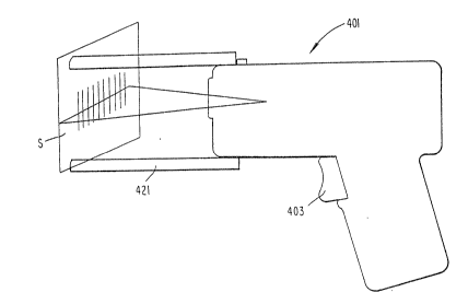
possible to adapt the spacer for use on a moving spot
type laser scanner, as shown in Figure 4. As
illustrated, the scanner 401 is a pistol grip type
moving spot laser scanner. Normally, the operator
holds the scanner 401 in one hand, points the scanner
at the code to be scanned and pulls the trigger 403.
The scanner emits a beam of light which reciprocates
back and forth across the code, and a photodetector
within the scanner housing senses the light reflected
back from the code.
To provide a desired long fixed spacing from the
optically encoded indicia, particularly for scanning
dot matrix type low density bar codes, the operator
places a spacer 421 on the fore end of the scanner 401.
2S The operator holds the asse~oly so that the spacer 421
contacts the surface S on which the code is formed.
The spacer positions the scanner 401 back away from the
code to increase the distance between the laser source
and the code. This again serves to increase the size
of the beam spot at the point of impact as the beam
scans across the surface. When the operator activates
trigger 403, the scanner 401 produces a moving laser
-
2 ~ ù~l
736-005 24
beam with a large spot size and scans that beam across
the dot matrix bar code.
The optical reader of the present invention can
take many forms, and may be combined with other means
to enter data other than the optically encoded data.
Figure 5 shows an exemplary embodiment of the pistol
grip type moving spot laser scanner ~01. The scanner
includes a generally gun-shaped housing having an
elongated body portion including a fron~ region 51, a
rear region 53, and an intermediate body region 52. To
detect optically encoded indicia, the housing contains
a moving spot optical scanner and associated
photodetector.
Commonly assigned application Serial No.
07/193,265 filed May 11, 1988, discloses a mirrorless
optical scanner, and application Serial No. 07/699,417
filed on May 13, l991 discloses incorporation of such a
scanner in a modular scanner component system facili-
tating use of the scanner in a variety of different
housing configurations. For the moving spot scanner
embodiments, the present invention preferably uses a
scanner similar to that disclosed in these two
copending applications, as discussed below with regard
to Figure 7. The disclosures of these two applications
are incorporated herein by reference in their entirety.
The scanner transmits a light beam through the
forward facing inclined window 60 formed in the
intermediate body region 52. When the operator aims
the scanner at the indi.cia, e.g. at the bar code, the
beam passes along a light path toward the indicia, and
the photodetector will receive light reflected from the
- . .; . ~ .
"
2 ~
736-005 25
indicia to produce electrical signals representative of
the indicia.
A keyboard 55, disposed on the upper surface in
the rear region 53 of the housing includes a number of
individual keys 58. This positioning of keyboard 55
places it out of ~he path of the emitted beam and out
of the path of the reflected light. .An operator manu-
ally enters alphanumeric data and/or selects specific
functions by activation of the keys sa of the keyboard
55. Because of its location, when the operator
activates the keys, the operator's fingers will not
block or otherwise interfere with the emitted light
beam or the light reflected from the scanned sy~bols.
A display device 54 is located on the upper
surface of the front region 51 of the housing for
displaying a variety information. In this embodiment,
the display is oriented so that the flat upper surface
of the display 54 is parallel ~o the path of the
emitted beam of light. The display 54 is a touch
sensitive display and data input device. ~hen certain
information is displayed calling for a user input, the
operator can select functions or input certain related
data by simply touching the corresponding area of che
display screen 54. The display and touch panel of
device 54 may comprise the integrated liquid crystal
display and optical touch panel disclosed in U.S.
Patent No. 4,916,308 to Meadows.
The embodiment of Figures 6A and 6B, incorporates
the moving spot scanner into a flat panel or tablet
type unit with a touch sensitive display device similar
to but somewhat larger than the touch sensitive display
54 used in the embodiment of Figure 5. The scanner is
. .' ~'
: .
2 ~ 3 ~ ~
736-005 26
positioned within the flat panel unit so as to emit the
beam through a window in the rear surface of the unit.
A switch within the panel, ~or example a mercury
switch, is sensitive to the orientation of the device.
When oriented for holding with the right hand (Figure
6B), the switch conditions the associated electronics
to operate the panel as a display and touch sensitive
data input device. In this mode, the touch panel
allows the user to input function selections and/or
data simply by touching a position on the display
screen, as in Figure 6B. When oriented for holding
with the left hand, as in Figure 6A, the switch
conditions the associated electronics to operate the
unit as an optical reader. In this mode, a touching of
the display panel acts as a trigger to activate the
moving spot scanner and read optically encoded
information scanned by the emitted beam.
In still further embodiments, the present
invention incorporates elements of an optical reader
into the stylus of a tablet type data input device. As
shown or example in Figure 7, the stylus arrangement
comprises a hand-held housing 12 containing a
lightweight, high-speed, miniature scanning motor 20
similar to that described in U.S. Patent No. 4,496,831.
The motor 20 repetitively drives an output shaft 22 in
alternate circumferential directions over arc lengths
less than 360 in each direction about an axis along
which the shaft extends. U.S. Patent No. 4,~96,831
provides structural, functional and operational details
of the motor 20 and of the associated motor control
circuitry 2~.
.,
. :. .:
: , .,: :: :
2 3 ~ 7~ ~fJ~
?36-005 27
A generally U-shaped support structure 26 is
mounted at the end of the shaft 22 of motor 20, in the
stylus 10 of Figure 7. U-shaped structure 26 supports
a laser emitter and optics assembly 28. As the motor
20 repetitively drives output shaft 22 in alternate
circumferential directions, the subassembly 28 and the
support structure 26 jointly oscillate and turn with
the shaft 22.
The subassembly 28 includes an elongated hollow
tube 30, a laser diode 32 fixedly mounted at one axial
end region of the tube 30, and a lens barrel 34 mounted
at the opposite axial end region of the tube 30. The
lens barrel contains a focusing lens (not shown); and
the lens barrel may provide an aperture stop, if
necessary, to define the beam diameter and thereby the
effective sensing spot of the scanner. The ~ocusing
lens is preferably a plano-convex lens, but may be
spherical, convex or cylindrical. U.S. Patent ~o.
4,816,660 describes the subassembly 28 in detail. The
solid state laser diode 32, of the subassembly 28,
generates an incident laser beam, either in the
invisible or visible light range. The lens focuses the
laser beam such that the beam cross-section or beam
spot will have a certain waist size at distances within
a working range relative to the housing 12. The
focused beam passes through the window 40; and during
the alternate, repeti~ive oscillations of the shaft 22,
as the support 26 and the subassembly 28 concurrently
oscillate, the beam spot is be swept in an arc across
the encoded information or bar code svmbol.
A portion of the light reflected off the symbol
passes along a return path back through the window 40
. '
.
. .
.. . . : ::
~ ~ ~ 7
736-005 2~
to a photodetector 44. Photodetector 44 senses the
variable intenslty of the returning portion of the
reflected laser light and generates an electrical
analog signal indicative of the detecled variable light
intensity. In the illustrated embodiment, the
photodetector 44 is stationarily mounted, but could be
mounted on the support structure 26 for oscillatlon
with the laser and optics subassembly 28.
In addition to the control circuitry 24 for
controlling opera~ion of motor 20, the printed circuit
board 48 may contain signal processing circuitry and
microprocessor control circuitry for converting the
analog electrical signal to a pulse signal, and for
analyæing the pulse signal widths and spacings to
derive digital data for the encoded symbols scanned by
the beam.
To scan encoded information using the stylus, the
user points the tip of the stylus 10 at the information
and activates a trigger button (not shown). The laser
diode emits a beam which scans the encoded information,
and the photodetector outputs an analog electrical
signal representative of any scanned symbols. A
digitizer processes the analog signal to produce a
pulse signal where the widths and spacings between the
pulses correspond to the widths of the bars and the
spacings between the bars; and the pulse signal from
the digitizer is applied to a decoder. The decoder
first determines the pulse widths and spacings of the
signal from the digitizer. The decoder then analyzes
the widths and spacings to find and decode a legitimate
bar code message.
.. , , .. :. . ~.:, .
,, :. ... ::
~' ' . : , ' . '' '
.. : ,. ~, ., .. . : : : '
2 ~
736-005 29
If the digitizer and decoder are elements of the
circuitry or software included on board 48, then the
decoded characters are transmitted to the associated
computer. In the embodiment of Figure 7, a cable
carries the digital data representing the decoded
characters to the associated computer, e.g. via ~he
connection to the display and resLstive stylus input
tablet. Alternatively, if the decoder and/or the
digitizer are elements of the circuitry or software
included in the computer or the associated tablet, then
the cable carries the analog outpu~ of the photo-
detector or the pulse signal output of the digitizer.
In the embodiment of Figure 7, the scanning beam
is emitted from the rear section of the stylus toward
the tip. To ensure proper spacing, the user may place
the tip of the stylus in contact with the surface on
which the information appears, in which case the body
of the stylus serves as a spacer similar to the spacer
421 shown in Figure 4.
For X,Y positional data input, the stylus of
Figure 7 would be used in combination with a data input
tablet, such as the resistive tablet disclosed in U.S.
Patent No. 4,972,496. The stylus includes a conductive
contact 46 at the tip to which a source voltage is
applied. The stylus may contain a voltage source, such
as battery (not shown), or the system may supply the
voltage to the stylus lO from an external source such
as the system power supply via the cable connection to
the tablet. The tablet includes an input screen for
determining an X,Y position on an electrically
resistive plate. To input data, the operator touches
the tip 46 of the s~ylus to the input screen. This
., , .
: :.:, .: i ;
,. . .. ..... . ...
. :, . ,.,.: . . ; , ;
:; ~ ,, , ~ . :-.
~7~
736-005 30
applies the voltage from the tip to the screen at the
touched position. The touched position is charged by
the stylus with a positive voltage with respect to a
plurality of plate measurement points, typically at
corners of the screen. The voltages at these plate
measurement points vary as a function of the distance
from the plate measurement points to the actual touch
position of the pen. These voltages are sequentially
measured in the X and Y directions by using
conventional means, such as an interface/multiplexer.
After analog-to-digital conversion of the detected
voltages, a microcontroller checks to ensure the
signal's numerical value is ~valid~ (e.g., is within
the possible range of voltages), and then converts the
lS voltages to X and Y distances.
As discussed above, the stylus embodiment uses
resistive contact type electronics such as disclosed in
U.S. Patent No. 4,972,496, to provide X,Y data input to
a digitizer tablet and display device~ Other forms of
stylus electronics, however, can be readily adapted to
use in the inventi.ve stylus. For example the stylus
electronics could rely on a light pen technology, on
capacitive contact detection circuitry, pressure
sensitive contact detection circuitry, ultrasonic
proximity detection circuitry, etc. In each case, the
key feature is that the stylus incorporates both the
electronics necessary to provide X,Y position data
input to an electronic tablet and the scanner and
detector and any associated electronics of a op~ical
reader such as a bar code scanner.
Also, in the above embodiment, a cable provides
power to the stylus and carries various signals from
: : .
:: : , , : : :
2~97~6~
736-005 31
the stylus to the associated computer system.
Alternatively, the stylus may include a battery to
supply power and a wireless transmitter. The
transmitter could be a radio transmitter, an infrared
transmitter, an ultrasonic transmitter or any other
type wireless transmitter. The transmitter sends
analog or digital signals resulting f.rom the scan of
the optically encoded information to the associated
computer system.
The stylus of Figure 7 directs the scanning beam
from the rear section of the stylus toward the tip. ~n
alternate embodiments of the stylus, shown in Figures 8
and 9, the scanner emits a beam in the opposite
direction. As shown in Figure 8,' the stylus is shaped
like a pen with an enlarged distal end. The enlarged
distal end of the stylus housing contains a moving beam
l,aser scanner engine 82. The scanner engine could, for
example, comprise a scanner motor, a support structure
mounted on the motor shaft and a laser and optics
subassembly similar to components 20, 26 an~ 28
discussed above relative to Figure 7, or the scanner
engine could comprise any conventional emitter and
scanning optics which are small enough to fit into a
stylus housing of convenient dimensions.
The enlarged distal end of the stylus housing also
contains a photodetector 83, for example a light
sensitive photodiode. The scanner engine 82 emits a
scanning beam through a window formed in the rear
surface of the stylus housing. A portion of the light
reflected off the symbol passes along a return path
back through the window to the photodetector 83.
Detector 83 senses the variable intensity of ~he
,: ` . ''
, . .
.
73~
736-005 32
returning portion o the reflected laser light over a
field of view and generates an electrical analog signal
indicative of the detected variable light intensity.
The housing also con~ains electronics 84 for the
optical reader. These electronics will inciude at
least the circuitry necessary to drive the scanning
motor, and may include circuitry such as the digitizer
and/or decoder for processing the signal from the
photodetector. A scan switch 81 mounted near the fore
end portion of the stylus serves as a trigger to
activate the scanning engine 82, photodetector 83 and
scanner electronics 84. The cable 85 optical carries
signals representing the information scanned to the
associated computer system. To operate the optical
reader, the user holds the fore end portion of the
stylus, points the distal end of the stylus at the
information to be scanned and presses switch 91.
The fore end portion of the stylus contains the
electronics 80 necessary to operate the stylus for X, Y
positional data input to a digitizer tablet. The
stylus could include a conductive contact at the tip
and means to apply a source voltage to the tip, as in
Figure 7, or any other form of stylus electronics as
mentioned above. In this embodiment, the cable 85
supplies all power to the stylus for operation of both
the stylus electronics 80 and the scanning engine 82,
photodetector 83 and scanner electronics 84 of the
optical reader system.
Figure 9 shows a combination stylus and optical
reader s.imilar to that of Figure 8 but using a wireless
transmitter to send signals representing scanned
information to the associated computer system. The
: ,, , . ,,~ . :
736-Q05 33
stylus of Figure 9 again is shaped like a pen wi~h an
enlarged distal end. The enlarged distal end of the
stylus housing contains a moving beam laser scanner
engine 92, similar to the engine 82 discussed above.
S The enlarged distal end of the stylus housing also
contains a photodetector 93, for example a light
sensitive photodiode. The scanner engine 92 emits a
scanning beam through a window formed in the rear
surface of the stylus housing. A portion of the light
reflected off the symbol passes along a return path
back through the window to the photodetector 93. The
housing also contains electronics 94 for the optical
reader which include at least the circuitry necessary
to drive the scanning motor, and may include circuitry
such as the digitizer and/or decoder for processing the
signal from the photodetector. A scan switch 91
mounted near the ore end portion o~ the stylus serves
as a trigger to activate the scanning engine 92,
photodetector 93 and scanner electronics 94. Again, to
operate the optical reader, the user holds the fore end
portion of the stylus, points the distal end of the
stylus at the information to be scanned and presses
switch 91.
The fore end portion of the stylus contains the
electronics 90 necessary to operate the stylus for X, Y
positional data input to a digitizer tablet. The
stylus could include a conductive contact at the tip,
as in Figure 7, and a battery 92 to apply a source
voltage to the tip, or the stylus could con~ain any
other form of stylus electronics as mentioned above.
A wireless transmitter 96 sends analog or digital
signals resulting from the scan of the opticaLly
: , .
- ~ 2 ~ ~ 7 3 i~ ~
73~-005 34
encoded information to the associated computer system.
The transmitter could be a radio transmitter, an
infrared transmitter, an ultrasonic ~ransmitter or any
other type wireless transmitter. In this embodiment,
the battery 92 supplies all power to the stylus for
operation of both the stylus electronics 90 and the
scanning engine 92, photodetector 93 and scanner
electronics 94 of the optical reader system and power
to the wireless transmitter 96.
In a further embodiment, the present invention
incorporates the optical scanner, for reading optically
encoded indicia, into a mouse type data input device.
This embodiment would include a mouse with relatively
standard electronics. Figure 10A, for example, shows a
track ball 43 and associated movement detection
electronics 45. The housing of the mouse also contains
a moving spot optical scanner module and associated
photodetector.
The housing is adapted for grasping, typically in
the palm of a user's hand, for manual movement across a
flat surface. When located on the flat surface, the
track ball extends through an opening in ~he bottom
surface of the housing. During movement of the mouse
across the surface, the track ball 43 engages the
surface, and the associated electronics 45 detect the
extent of the manual movement of the device across the
surface. One or two keys are located in the top of the
housing (see Figure 10B). ~anual depression of these
keys operates switches (not shown) within the mouse
housing to provide an operator input. These elements
of the embodiment of Figures 10A and 10B pro~ide
standard "mouse" type inputs to an associated computer.
.. .~ : - : .. :
. ~ . . ,. . . , ~ , . :
~ ,. : : , . ~ :
: :: : : ~ : . .. .: :
~. :
,
736-005 35
As in the stylus of Figure 7, the mouse
arrangement of Figure lOA comprises a housing
containing a lightweight, high-speed, miniature
scanning motor 20 similar to that described in U.S.
Patent No. 4,496,831. The motor 20 repetitively drives
an output shaft 22 in alternate circumferential
directions about an axis along which the shaft extends
over arc lengths less than 360 in each dixection. U-
shaped structure 26 supports a laser emitter and optics
assembly 28. As the motor 20 repetitively drives
output shaft 22 in alternate circumferential
directions, the subassembly 28 and the support
structure 26 jointly oscillate and turn with the shaft
22. The subassembly 28 includes an elongated hollow
lS tube 30, a laser diode 32 fixedly mounted at one axial
end region of the tube 30, a lens barrel 34 mounted at
the opposite axial end region of the tube 30. The lens
barrel contains a focusing lens ~not shown) such as a
plano-convex lens, but may be spherical, convex or
cylindrical
The solid state laser diode 32, of the subassembly
28, generates an incident laser beam, either in the
invisible or visible light range. ~he lens focuses the
laser beam which is reflected off of a mirror 49, and
~5 the focused beam passes through the window 40. In this
embodiment, the window 40 is formed in the bottom
surface of the mouse housing such that the beam cross-
section or beam spot will have a certain waist size at
distances within a working range relative to the
housing. Instead of using the mirror 49, the motor,
support and emitter and optics assembly could be
positioned to emit light downward through window 40
. ~ . : .
2 ~ ~ ~ 3 :3 ~
736-005 36
directly. In either case, during the alternate,
repetitive oscillations of the shaft 22, as the support
26 and the subassembly 28 concurrently oscillate, the
beam spot sweeps through an arc across the encoded
information or bar code symbol positioned a distance
below the lower surface of the mouse housing.
The scanner emits a beam of light from the bottom
surface of the mouse housing, and the photodetector 44
detects the variable intensity of the returning portion
of the reflected light and generates an electrical
analog signal indicative of the detected variable light
intensity. Typically, at least the digitizer for
converting analog signals from the photodetector to a
pulse signal would also be located within the housing
of the mouse.
The embodiment of Figures lOA and lOB includes a
third trigger on the mouse to activate the optical
reader components (see plan view of Figure lOB).
Typically, the user picks up the mouse, orients it so
as to direct the beam along a path toward the
information to be scanned, and activates the third
trigger switch 42 on the top surface of the housing to
activate the moving spot scanner and associated
photodetector. When the user has not activated switch
42, the unit operates as a standard computer mouse.
A second ver~ion of the mouse includes a contact
switch 42~ mounted in the lower surface of the housing,
as shown in Figure 11. The mouse includes the
components of an optical reader engine or module 70
similar to the components 20, 26 and 28 discussed above
and includes a standard track ball and position detec-
tion electronics similar to 43 and 45. The contact
. . .
736-005 37
..
switch detects when the mouse is resting on a surface
and controls the device to provide standard mouse type
signals to the associated computer. When the operator
lifts the mouse off the surface, however, the contact
switch triggers operation of the optical reader module
70. The operator then points the mouse so that the
beam scans across the optically encoded indicia.
In the mouse embodiments illustrated in the
drawings, the mouse connects to the associated computer
via a cable (Figures lOB and 11). This cable could
connect to a port on the back of the computer or to a
port on the keyboard. The cable supplies all necessary
power to the movement detection electronics 45 and any
circuitry needed to detect button operation, and it
supplies all necessary power to the laser diode 32 and
motor 20 of the scanner, the photodetector 4~ and the
associated electronics for processing the signal from
the photodetector. As an alternative, the mouse could
incorporate a battery and a wireless transmitter
similar to the transmitter 96 in the embodiment of
Figure 9. The transmitter would send analog or digital
signals resulting from the scan of the optically
- encoded information to the associated computer system
and the signals relating to the mouse movement and
button operation. The battery would supply all power
to the mouse for operation of both the mouse type
electronics and the optical scanning, detection and
signal processing electronics for optical reading of
indicia.
T~pically, the light beam emitted by the scanners
of the present invention will be in the visible range
of the spectrum, for example red light. Consequently,
':
` ~ :
2i~ '7~ ~
736-005 38
the beam scan across the code or indLcia will be
visible to the operator. The decode logic may reside
within the same housing as the scanner, for example in
the integrated terminal embodiment, or the decode logic
S may be software resident in the associated computer
system. The decode logic can provide a "beep" signal
as an audible output upon detection of a valid read
result. The visible beam and the ~beep~ signal provide
feedback to the operator as to the operation of -the
scanner.
Although the integrated terminals of Figures 5-11
have been described as using a moving spot scanner, it
would be a simple matter to substitute a fixed beam
emitter. For example, a fixed laser emitter and
optics, such as shown in the wand of Figure lA, might
replace the components for proclucing the scanning
laser.