Note: Descriptions are shown in the official language in which they were submitted.
2099560 64421-534
BACKGROUND OF THE INVENTION
A. Field of the Invention
The present invention relates to printing apparatus and
methods, more particularly to improved apparatus for printing
single- or multiple-color copies using digital spark-discharge
recording technology.
B. Description of the Related Art
Traditional techniques of introducing a printed image
onto a recording material include letterpress printing, gravure
printing and offset lithography. All of these printing methods
require a plate, usually loaded onto a plate cylinder of a rotary
press for efficiency, to transfer ink in the pattern of the image.
In letterpress printing, the image pattern is represented on the
plate in the form of raised areas that accept ink and transfer it
onto the recording medium by impression. Gravure printing plates,
in contrast, contain series of wells or indentations that accept
ink for deposit onto the recording medium; excess ink must be
removed from the plate by a doctor blade or similar device prior
to contact between the plate and the recording medium.
~ ~'.,''
WO92/12011 PCT/US92/00 ~
~o9956~ -2-
In the case of offset lithography, the image is present
on a plate or mat as a pattern of ink-accepting (oleophilic)
and ink-repellent (oleophobic) surface areas. In a dry
printing system, the plate is simply inked and the image
transferred onto a recording material; the plate first makes
contact with a compliant intermediate surface called a blanket
cylinder which, in turn, applies the image to the paper or
other copying medium. In typical rotary press systems, the
recording medium is pinned to an impression cylinder, which
brings it into contact with the blanket cylinder.
In a wet lithographic system, the non-image areas are
hydrophilic, and the necessary ink-repellency is provided by an
initial application of a dampening (or "fountain") solution to
the plate prior to inking. The fountain solution prevents ink
from adhering to the non-image areas, but does not affect the
oleophilic character of the image areas.
The plates for an offset press are usually produced
photographically. In a typical negative-working subtractive
process, the original document is photographed to produce a
photographic negative. This negative is placed on an aluminum
plate having a water-receptive oxide surface coated with a
photopolymer. Upon exposure to light or other radiation
through the negative, the areas of the coating that received
radiation (corresponding to the dark or printed areas of the
original) cure to a durable oleophilic state. The plate is
then subjected to a developing process that removes the uncured
areas of the coating (i.e., those which did not receive
radiation, corresponding to the non-image or background areas
of the original), and these non-cured areas become oleophobic
and/or hydrophilic.
If a press is to print in more than one color, a
2099560
64421-534
separate printing plate corresponding to each color is required,
each such plate usually being made photographically as just
descri~ed. In addition to preparing the appropriate plates for
the different colors, the operator must mount the plates properly
on the plate cylinders of the press, and coordinate the positions
of the cylinders so that the color components printed by the
different cylinders will be in register on the printed copies.
Each set of cylinders associated with a particular color on a
press is usually referred to as a printing station.
In most conventional presses, the printing stations are
arranged in a straight or "in-line" configuration~ Each such
station typically includes an impression cylinder, a blanket
cylinder, a plate cylinder and the necessary ink tand, in wet
systems, water) assemblies. The recording material is transferred
among the print stations sequentially and in register, each
station applying a different ink color to the material to produce
a composite multi-color image. Another configuration, described
in U.S. Patent No. 4,936,211 co-owned with the present
application, relies on a central impression cylinder that carries
a sheet of recording material past each print station, eliminating
the need for mechanical transfer of the medium to each print
station.
With either type of press, the recording medium can be
supplied to the print stations in the form of cut sheets or a
continuous "web" of material. The number of print stations on a
press depends on the type of document to be printed. For mass
copying of text or simple monochrome lineart, a single print
station may suffice. To achieve full tonal rendition of more
complex monochrome images, it is customary to employ a "duotone"
approa~h, in which two stations apply different densities of the
same color or shade. Full-color presses apply
.....
WO92/12011 PCT/US92/00 ~
2099560
,, ~ ,;;
ink according to a selected color model, the most common being
based on cyan, magenta, yellow and black (the "CMYK" model).
Accordingly, the CMYK model re~uires a minimum of four print
stations; more may be required if a particular color is to be
emphasized. The press may contain another ctation to apply
spot lacquer to various portions of the printed document, and
may also feature one or more "perfection" assemblies that
invert the recording medium to obtain two-sided printing.
A number of difficulties attend both the platemaking and
ink-transfer stages of printing. The photographic process used
to produce conventional plates is time-consuming and requires a
facility and equipment adequate to support the necessary
chemistry. To circumvent this process, practitioners have
developed a number of electronic alternatives to plate imaging,
some of which can be utilized on-press. With these systems,
digitally controlled devices alter the ink-receptivity of blank
plates in a pattern représentative of the image to be printed.
Such imaging devices include sources of electromagnetic-
radiation pulses, produced by one or more laser or non-laser
sources, that create chemical changes on plate blanks (thereby
eliminating the need for a photographic negative); ink-jet
equipment that directly deposits ink-repellent or ink-accepting
spots on plate blanks; and spark-discharge equipment, in which
an electrode in contact with or spaced close to a plate blank
produces electrical sparks to physically alter the topology of
the plate blank, thereby producing "dots" which collectively
form a desired image.
While these digital platemaking technologies have
alleviated many of the disadvantages associated with more
traditional approaches, they are not free from drawbacks of
their own. Such drawbacks are described in U.S. Patent No.
4,911,075 (co-owned with the present application and hereby
incorporated by reference).
92/12011 PCT/US92/00314
209~560
Presses must also be provided with me~-h~n;cal assemblies
for maintaining and correcting registration among the images
applied by the various print stations. In the case of an in-
line press, it is neces-~Ary to employ very accurate paper-
feeding and paper-transfer mPchA~;sms, as well as precision
gearing, to assure consistent positioning among print stations.
The press should also allow for correction of misregistrations
by adjustment of the relative positions of the plate cylinders
to maintain proper rotational, axial and skew-orientation
phase; so long as the paper is fed and transferred accurately
among print stations, such positioning corrections will correct
misregistrations on a consistent basis.
The mechanical difficulties of maintaining registration
are ameliorated, but not eliminated, if the plate is to be
imaged on-press. In this case, mispositioning due to improper
mounting of the finished plate onto the plate cylinder is
effectively overcome. However, in a multi-station press, it
becomes neC~c~ry to maintain registration among plate
cylinders during both the plate-imaging and printing stages.
Specifically, not only must the print stations apply ink in
register with one another, but each individual plate-imaging
system must be coordinated both with its own plate cylinder
(which holds the plate to be imaged) and with one another so as
to maintain consistent plate orientations.
The ink flow at each print station must also be
accurately regulated, as well as remain adjustable to
accommodate different ink densities or produce a desired color
correction on the final printed copy. As discussed in U.S.
Patent No. 4,058,~58, a press may be equipped with a number of
electrically controlled ink-regulating screws or keys
distributed across the press to regulate the amount of ink that
the ink fountain at each print station applies to the plate
WO92/12011 PCT/US92/00
20995t60~ 6-
cylinder at that station. These regulators may be controlled
manually or, to some extent, with the assistance of computer
equipment. In some publishing systems, for example, the color
separations prepared from each page mock-up are scanned and
stored digitally as proofs; hard copy produced by the press is
similarly scanned, and digitally compared with the mock-up
proofs to determine the neC~c~ry ink-regulation adjustments.
Thus, at present, an operator must devote time and/or skilled
judgment to determine the settings of ink regulators.
DESCRIPTION OF THE INVENTION
A. Brief SummarY of the Invention
The invention comprises a number of interrelated and
cooperative elements that facilitate electronic imaging,
preferably on-press, of one or more lithographic plates, and
printing with such plates on various types of presses. The
invention includes mechanical and electrical elements that
maintain alignment and registration of a plurality of imaged
plates, and allow feedback-controlled ink regulation to
eliminate, or at least reduce, the necessity of having an
operator manually key the ink settings.
Our printing apparatus, which can be configured as an
in-line press, a central-impression press or any other workable
lithographic press design, is designed to accept electronic
signals that represent monochrome or color-separated images to
be printed, and use these signals to control an imaging device
that creates an image on a plate blank. The plate blank may be
mounted and imaged on-press, i.e., on the plate cylinder that
will ultimately accept ink and transfer the image to a blanket
cylinder, or off-press on a separate imaging assembly.
Recording material may be fed to the press as cut sheets or in
a web, and may consist of paper, film, metal foil, or a
2099560 64421-534
composite of two or more of the foregoing (e.g., film laminated
onto paper).
The electronic imaging assembly or assemblies can be
based on any of several types of technology, the primary
requirement being amenability to digital operation and control.
Suitable technologies, all of which are well-characterized in the
art, include laser and non-laser pulsed sources of electromagnetic
radiation, electron-beam scanning apparatus, ink-jet equipment,
and spark-discharge imaging equipment. Each imaging assembly
responds to incoming picture signals representing the respective
color component of the original document or picture to be printed
by the particular printing station.
Our preferred imaging system is a high-voltage, non-
contact spark-discharge or plasma-discharge apparatus, as
described in U.S. Patent No. 4,911,075 and U.S. Patent No.
5,062,364.
The invention addresses registration errors in several
ways. On-press imaging itself eliminates registration errors
arising from mispositioning of the printing plates on the plate
cylinders. The on-press ~onfiguration also facilitates correction
of periodic registration errors by electronic control of the
relative phases of the plate cylinders or the timing of the
picture signals applied to the imaging devices, so that the phases
of the images are kept identical.
,~
. =, s~
C t ' 2099560
.
We also employ an electronlc controller to
automatlcally set and ad~ust the lnk-regulatlon mechanlsm,
based on the percentage of coverage for a partlcular key
and/or the output of a flash densltometer. The lnk settlngs
provlded by the controller can, of course, be overrldden
manually.
Operatlon of the apparatus is supervlsed by a
central computer, whlch can also be programmed to provlde such
pre-press functlons as edltlng and raster-lmage processlng.
In a flrst preferred embodlment there ls provlded, a
prlntlng apparatus comprislng at least one prlnt statlon, each
statlon lncludlng a plate cyllnder for supportlng a prlntlng
plate, at least one dlscharge source for applylng an lmage to
the plate and means for movlng each dlscharge source relatlve
to the plate cyllnder 80 that when the plate cyllnder ls
rotated, the at least one dlscharge source scans a raster on
the surface of the plate; means for rotatlng each cyllnder,
and control means responslve to electronlc slgnals
representlng an orlglnal document for repeatedly actuatlng the
dlscharge source momentarlly durlng the scan thereof so that
sald dlscharge source forms on the plate surface an lmage
comprlsed of dots correspondlng to the orlglnal document, sald
control means lncludlng, a dot posltlon look-up table for
storlng the x and y coordlnates correspondlng to substantlally
all dot posltlons on the plate; means for actuating sald
dlscharge source to form lmage dots at selected ones of sald
dot posltlons when sald electronlc slgnals are present; and
means for offsettlng, wlth respect to sald x and y
C 64421-534
~ 2099560
coordinates, the actlon of the discharge-source actuatlon
means to correct imaging errors.
In a second preferred embodiment there ls provided,
prlntlng apparatus comprislng at least one print station, each
prlnt statlon lncludlng a prlnt cylinder for supporting a
printing plate, at least one dlscharge source for applying an
image to the plate and means for moving each dlscharge source
relative to the plate cylinder so that when the plate cyllnder
is rotated, the at least one dlscharge source scans a raster
on the surface of the plate to produce an array of image dots;
means for rotating each cylinder; lnk-regulatlng means
responsive to lnk-control slgnals at each prlnt statlon for
regulatlng the amount of ink applied to the plate on the plate
cylinder of that station~ and ink-control means for providing
lnk-control slgnals to sald regulatlng means, sald lnk-control
means countlng the number of lmage dots to be formed by each
prlnt statlon on selected portions of said plate and
controlllng sald lnk-regulatlng means at that statlon based on
the number of dots to be prlnted by that prlnt station on sald
selected plate portlons.
In thlrd and fourth preferred embodlments there ls
provlded, a prlntlng apparatus comprlslng a plate cyllnder; ln
the third embodlment, means for securlng, to the plate
cyllnder, a prlntlng plate havlng a prlntlng surface and
lncludlng a metal flrst layer and a second layer underlylng
sald flrst layer, sald first and second layers having
different affinities for a printing liquid selected from the
group consisting of water and ink7 and means for exposing the
- 8a -
64421-534
C
-
2099~
.
printing surface to spatial spark discharges between said
plate and an electrode spaced close to said prlnting surface
to remove sald metal flrst layer and expose sald second layer
at sald selected polnts on the plate; ln the fourth
embodlment, means for securlng, to the plate cyllnder, a
prlnting plate having a prlnting surface and lncludlng an
oleophoblc flrst layer, a metal second layer underlylng said
flrst layer and an oleophoblc thlrd layer underlylng isald
second layer7 means for exposlng the prlntlng surface to
spatlal spark dlscharges between sald plate and an electrode
spaced close to sald prlntlng surface to remove sald flrst and
second layers and expose sald thlrd layer at sald selected
polnts on the plate; ln both embodiments means for movlng the
electrode and prlnt cyllnder relatlvely to effect a scan of
the prlntlng surface by the electrode; and means for
controlllng the spark dlscharges in accordance with electronlc
signals representing an image so that they occur at selected
tlmes ln the scan, thereby dlrectly produclng on the plate an
array of lmage spots whlch can be inked to make coples of the
document represented by the electronic signals.
In fifth and sixth preferred embodlments there is
provided, an apparatus for imaging a llthographic plate, sald
apparatus comprlslng in the fifth embodiment, means for
supporting a lithographic plate having a printing surface and
including a metal layer and a second layer underlying said
metal layer, said metal and second layers havlng dlfferent
afflnitles for a printing liquid selected from the group
conslstlng of water and lnk7 ln the slxth embodlment, means
- 8b -
64421-534
C~
~ 209956~
for supporting a llthographic plate having a printing surface
and lncluding an oleophobic flrst layer, a metal second layer
underlylng sald flrst layer, and an oleophlllc thlrd layer
underlylng sald second layer; in both embodlments, at least
one spark-dlscharge source, each of whlch lncludes a wrltlng
head comprlslng an electrodeS means for posltloning the source
close to the prlntlng surfaceS and means for dellverlng hlgh-
voltage pulses ln excess of 2000 volts to each electrode to
produce spark dlscharges substantlally perpendlcular to the
prlntlng surface wlthout contactlng the prlntlng surface wlth
the nozzle, sald dlscharges belng of sufflclent strength to
remove sald metal layer and expose sald second layer at the
selected polnts, thereby changlng the afflnlty of sald
prlntlng surface for sald llquld at sald polnts.
In further embodlments, methods based upon the thlrd
through slxth preferred embodlments descrlbed above are
lntended to lle within the scope of this invention.
B. Brief Descrlptlon of the Drawlnqs
The foregolng dlscussion wlll be understood more
readlly from the followlng detalled descrlptlon of the
lnventlon, when taken ln con~unctlon wlth the accompanylng
drawlngs, in whlchs
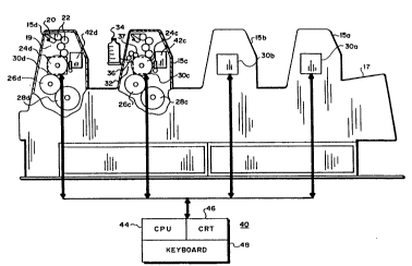
FIG. 1 ls a side elevational and schematic view of
an offset color press incorporating the features of our
inventlon; and
- 8c -
C 64421-534
i~ 2099560
FIG. 2 is a diagrammatic view of a test print used
to align and color-callbrate the press.
C. Descrlptlon of the Preferred Embodiments
1. Press Conflgurations
For ease of explanatlon, we wlll descrlbe an
lllustratlve embodlment of our lnventlon as lncorporated lnto
a conventlonal ln-llne press. However, lt should be
understood that the prlmary features of our lnventlon can also
be utllized in con~unction with a central-impression press, as
described ln U.S. Patent No. 4,936,211, or any other direct-
lmpression or offset-impresslon press deslgn.
Refer flrst to FIG. 1, which is a side elevational
view
- 8d -
C 64421-534
~ ,~
~92/12011 PCT/US92/00314
2099S~0
of our in-line-press embodiment with cutaway views of two print
towers. The press comprises a series of four print stations or
towers 15a, 15b, 15c and 15d, each of which contains the
n~C~ccAry equipment (to be described in detail below) to apply
ink or lacquer to a recording material. Although four print
stations are illustrated, it should be understood that
conventional presses can contain as few as one or as many as 10
or more such stations, depending on the nature of the printing
to be performed.
Individual sheets of recording material are fed to the
print stations from a tray 17 at the right side of the press as
viewed in FIG. 1. A conventional handling m~chAn;~m (not
shown) draws the topmost sheet from tray 54 and carries it to
the first print station 15a, where it is wrapped around an
impression cylinder and inked. Thereafter, the sheet is
stripped from this impression cylinder and carried to the
second print station 15b where a similar operation is
performed, and so on. The handling mechanism maintains
registration and alignment of the material as it is transported
across the press, and may contain a "perfection" assembly that
turns the sheet upside down between print stations for two-
sided printing.
The cutaway view of FIG. 1 illustrate the components of
two representative print stations 15c, 15d. Station 15d, which
is configured for dry printing, includes an ink fountain
assembly 19 that comprises an ink tray 20, which transfers ink
via a series of rollers 22, and means for automatically
controlling ink flow so that the amount and distribution of ink
can be regulated electronically. The rollers 22 transfer ink
to the surface of a plate cylinder 24d, which makes surface
contact with a blanket cylinder 26d of the same diameter, and
that cylinder, in turn, is in surface contact with an
impression cylinder 28d. The print station also includes a
~ ~r g~
2099560
controller, shown ln phantom at reference numeral 30d, which
monitors the angular position of plate cylinder 24d and also
furnishes ink-control signals to ink fountain assembly 19. A
sultable controller design is described ln U.S. Patent No.
5,174,205; however, for purposes hereof, the controller can be
any suitable angular positloning and monitorlng system.
The press can also be configured to prlnt webs of
recordlng materlal by addition of suitable feeding equlpment
on the intake side of the press (in lieu of tray 17), and
complementary uptake equipment on the output side.
Print station 15c ls configured for web printing; in
actual practice, it would be unusual to employ both wet and
dry printing stations in the same press, and both types are
shown in FIG. 1 for illustrative purposes. Print station 15c
contains all of the features of print station 15d, as well as
a dampening system 32, which comprlses a water source 34 that
feeds water to a water tray 36. A series of dampening rollers
37 transfer water from water tray 36 to plate cylinder 24c.
For this statlon, controller 30c regulates dispensation both
of water and ink.
Preferably, the printing stations are equlpped wlth
on-press imaging systems, indicated by reference numerals 42c
and 42d, although not all aspects of the invention require
this feature. The imaging system will be described in further
detail below.
The press also includes a computer, shown
schematically at reference numeral 40, which transfers image
data and control
-- 10 --
C 64421-534
~Lp92/12011 PCT/US92/00314
~ f . ~.
2093560
signals to controllers 30a, 30b, 30c and 30d. Connections
between computer 40 and the controllers are provided by
suitable cables. The press responds to digital signals,
supplied by computer 40, that represent an original document or
image.
Computer 40 comprises a central-processing unit (CPU)
44, which stores, retrieves and manipulates data; a cathode-ray
tube (CRT) or other suitable display 46 for communication with
the operator; and a keyboard 48, with which the operator enters
data and control commands. Computer 40 may be a single machine
or a set of processors configued to operate in parallel,
thereby dividing the workload and increasing the effective
processing speed. In a single machine, an equivalent
multiprocessor architecture can be produced by increasing the
number of central-processing units.
Using keyboard 48, the operator may enter instructions
for imaging the printing plates on-press, registration
information, and/or instructions relating to press control such
as ink-flow adjustment, number of copies to be printed, etc.
In addition, as discussed below, computer 40 can be provided
with certain "pre-press" functions that permit the operator to
process image and text data into output-ready form. CPU 44
may include one or more mass-storage devices, such as disks or
tape drives, to hold the typically large quantities of data
associated with digitized images.
2. Plates and Plate Imaqinq
As stated hereinabove, a number of imaging technologies
can be adapted for use on-press. Our preferred imaging system
is the spark-discharge or plasma-discharge equipment discussed
hereinabove, and as more fully described in the patents and
patent applications cited previously. Basically, in response
WO92/12011 PCT/US92/003 ~
2099~60 -12-
to incoming picture signals and ancillary image data supplied
by computer 40, high-voltage pulses having precisely controlled
voltage and current profiles are applied to one or more
electrodes or plasma-jet sources to produce precisely
positioned and defined arc or plasma-jet discharges to the
plate. These discharges physically transform selected points
or areas of the plate surface to render them either receptive
or non-receptive to ink and/or water.
The imaging system is preferably implemented as a
scanner or plotter whose writing head consists of one or more
electrode or plasma-jet sources positioned a small distance
above the working surface of the plate and moved relative to
the plate so as to collectively scan a raster on the plate
surface. To achieve the requisite relative motion between the
writing head and the cylindrical plate, the plate can be
rotated about its axis and the writing head moved parallel to
the rotation axis so that the plate is scanned
circumferentially with the image on the plate "growing" in the
axial direction. Alternatively, the writing head can move
parallel to the cylinder axis and after each pass of the head
the cylinder can be incremented angularly so that the image on
the plate grows circumferentially. The angular position of the
writing head with respect to the plate is monitored by a
controller, as discussed above, while a distance-sensing and
adjustment mec-hAn;sm (such as that described in copending
application serial no. 553,817) controls the distance of the
head away from the plate.
The power of the arc actually reaching the plate (i.e.,
its voltage/current profile) depends on the inherent breakdown
voltage associated with the ambient air or applied working gas,
the voltage (positive or negative) of the pulse applied to the
electrode or plasma-jet source, and the rise time of this
pulse. The interplay of these variables derives from the fact
~ 92/12011 PCT/US92/00314
2099560
that breakdown and arcing are not an instantaneous process.
Although the drop in resistance that accompanies breakdown
would ordinarily prevent maintenance of voltages above the
breakdown threshold, a very fast rise time can momentarily
impose voltage levels across the gap that exceed this threshold
during the finite time required for breakdown to occur.
The current range, on the other hand, depends both on
this effective arc voltage and the design of the pulse
circuitry. Furthermore, the electrical properties of the plate
can limit the maximum useful current, since insufficient
conductivity (e.g., due to use of too thin a layer of material
for a given current level) results in charge buildup that can
dim; ni ~h the strength of the arc or prevent arcing entirely.
Our preferred applied voltage levels -- that is, the voltage
actually supplied to the electrode or plasma-jet source, not
the effective arc voltage -- range from 1,000 to 5,000 volts;
potential levels above 2,000 volts are especially preferred.
As stated previously, the effective arc voltage for a given
applied voltage depends on the rise time of the voltage pulse
and the breakdown voltage of the ambient air or applied working
gas. Our preferred working current ranges from 0.1 to 1 amp.
Lower current levels tend to be associated with easily ionized
gases such as argon, and the higher levels with gases having
higher breakdown voltages, such as air.
By varying the applied voltage or current supplied to
the electrode, or the duration of its application, or the
number of discharges applied at a give location, it is possible
to produce image spots of variable sizes. Means for
accomplishing this are quite well-known in the art. Likewise,
dot size may be varied by repeated pulsing of the electrode at
each image point, with final dot size determined by the number
of applied pulses (pulse-count modulation).
2099560
64421-534
Our preferred plate constructions, designed for use with
thiæ type of imaging equipment, are described in U.S. Patent No.
4,911,075 and U.S. Patent No. 5,109,771. Briefly, these plates
contain, at a minimum, a conductive metal layer and a second layer
underlying the metal layer, the metal and underlying layers having
different affinities for ink and/or water. The spark discharges
are powerful enough to remove the metal layer and thereby expose
the underlying layer at selected points. When the scan is
complete, the points collectively form the image to be printed.
In a variation of this construction, suitable for dry
printing, the plate contains an oleophobic (e.g. silicone) first
layer, a metal second layer underlying this first layer, and an
oleophilic third layer underlying the second layer. To image this
type of plate, the spark discharges remove both the top and metal
layers but leave the bottom layer intact.
Use of a metal imaging layer confers two key advantages.
The first is high imaging accuracy. In a non-contact imaging
system, reproduction accuracy depends on the ability to prevent
the discharge from wandering as it travels from its source to the
surface of the plate. This ordinarily requires a high field
gradient between the discharge source and the point on the plate
that is to be imaged. The strongest part of the field on the
plate, to which the discharge is most strongly attracted, occurs
at the point precisely opposite the discharge source. However,
the strength of the field at this point must be sufficiently
greater than the strength at any other point to overcome the
inherently random nature of the discharge. The stronger the
gradient, the faster the field strength will diminish as the path
from source to plate deviates from the normal. Accordingly, high
discharge power creates a strong gradient, which in turn favors
straight-line discharge travel by emphasizing the recession of the
plate field strength in all
14
~,~
~ 92/12011 PCT/US92/00314
2099S60
directions away from the normal.
Second, high-energy discharges permit us to ablate
refractory materials. By employing strong surface and
substrate layers, we are able to produce lithographic plates
that offer longer performance lifetimes than those of the prior
art.
3. Press Operation
To operate the press in its imaging mode, the operator
first mounts plate blanks on each plate cylinder that will be
used for printing the finished document. He or she then
inserts a disk, tape, or any form of digital storage medium
carrying digital data representing the color separations of the
original document to be copied, and loads that data into the
internal memory of the computer 40. The operator can call up
the data and preview the image on display 46 before printing.
Upon operator command, computer 40 transmits picture signals
representative of that image data to controllers 3Oa, 3Ob, 30c
and 3Od, which are caused to actuate the associated imaging-
system writing heads and thereby apply corresponding images to
the plates on the respective plate cylinders.
Alternatively, press computer 40 can also be provided
with pre-press editing functions, such as raster-image
processing, that convert raw image data and text data (the
latter typically encoded in page-description language) into the
output-ready bitmap that is sent to the controllers as picture
signals. This capability introduces nearly all of the
production steps that precede actual output and publication
into the printing apparatus, resulting in a truly integrated,
digital press system. Pre-press editing functions can range
from basic raster-image processing, which "screens" image data
into halftone patterns and produces bitmaps from these patterns
_
WO 92/12011 PCI'/US92/003
r. f~, ,,
0 ' ~ - 1 6 -
and from encoded text information (that specifies, for example,
character fonts, scaling and orientation of the text), to full
editing capability that allows an operator to enter information
directly and manipulate it. Computer 40 performs these pre-
press functions when unoccupied with imaging tasks; for
example, since typical imaging rates are significantly slower
than the maximum rate at which a suitable computer can operate,
computer 40 can "multitask" imaging of one plate with pre-press
operations for another plate.
After the plates have been imaged (or after off-press
plate imaging and subsequent mounting of imaged plates to the
plate cylinders), the press can be operated in its print mode
to print proof copies of the original document, the number
being determined by the operator's instructions entered via
keyboard 48. If the colors printed on the copies are
acceptable, the operator can instruct the press to print the
required number of final copies. If changes are required, new
printing plates can be made using appropriately corrected image
data.
.
It is even feasible to make each plate cylinder house a
plate-material cassette containing a length of imageable
flexible mat or film that can be automatically advanced around
the plate cylinder to locate fresh lengthwise segments of the
mat or film on the cylinder surface. In this way, a plate with
a satisfactory and properly registered image can be created
very quickly and efficiently. The old image will be rolled up
inside of the plate cylinder at the same time as the new
material is dispensed.
4. ~orrection of Reqistration Errors
The press includes means for correcting various types of
cyclical mechanical error, such as axial misalignment and skew.
92/12011 PCT/US92/00314
-17-
2099~6Q
Our first registration-correction system operates during plate
imaging. At this time, it is neceCc~ry to maintain angular
coordination among plate cylinders so that similarly located
image spots are applied at consistent circumferential positions
on each cylinder. This requires coordination of each
individual plate-imaging system both with its own plate
cylinder (which holds the plate to be imaged) and with one
another.
In our central-impression embodiment, such coordination
takes place automatically, since the impression cylinder drives
each plate cylinder, allowing the angular position of all plate
cylinders to be determined by reference to the gear segments of
the impression cylinder. For the in-line embodiment, it is
necessary to establish the position on each plate where imaging
is to begin, orient the writing head opposite this position,
and maintain consistent spatial relationships between the
writing heads and their associated plate cylinders, so that
picture signals specifying particular image-spot positions will
cause imaging of the same physical locations on each plate. We
accomplish this by rotating each plate cylinder at
substantially identical and consistent angular velocity, and
including within each controller 30a, 30k, 30c and 30d an
angular encoder (suitable designs for which are well-
characterized in the art).
Computer 40, which is coupled to each of the
controllers, receives the output of the associated angular
encoders, and by appropriate control signals ensures consistent
rotation and angular coordination among the plate cylinders.
To establish consistent starting positions, as well as correct
for registrations errors caused by factors other than
misalignment, computer 40 has access to a dot-position lookup
table for each station (which may be included in CPU 44 or in
each of controllers 3Oa, 3 k, 30c and 3Od). The lookup table
WO92/12011 PCT/US92/00
2~ 6 18
stores the x and y coordinates of all dot positions of the
picture to be imaged. By performing a so-called end-to-end
test using plates imaged with simple test patterns (e.g.
vertical and horizontal lines), copies are printed. If certain
color lines deviate from the theoretical true position, the
differences are measured and suitable x and y offsets entered
into the lookup table at the locations therein corresponding to
the offending dots of the particular color. This calibration
step is performed only once at the factory during the final
check-out phase of press manufacture, and the corrected dot
positions for each color permanently stored in computer 40 or
the respective controller as the pedigree for each of the print
stations. Subsequent similar calibration is required only in
the event that certain parts of the press, e.g. gearing or
cylinders, had to be replaced.
FIG. 2 illustrates a two color print P printed by press
station 30c, printing a cyan image Ic, for example, and by
station 30d, printing a yellow image Iy~ for example. Because
plate cylinders 24c and 24d are out of phase with one another,
the yellow image is displaced axially (x direction) and
circumferentially (y direction) (i.e., it is out of register)
with respect to the cyan image Ic used as the position
reference. Accordingly, it is necessary to bring the
respective image-start positions into line with one another.
The yellow image is also skewed and is somewhat longer
because, for example, plate cylinder 24d is slightly longer in
diameter than plate cylinder 24c. Assuming that the images are
scanned circumferentially as in FIG. 2, if plate cylinder 24d
is even slightly larger in diameter then plate cylinder 24c,
the image dots formed on the plate for the color yellow will be
spaced further apart along a scan line then the corresponding
dots on the cyan plate imaged at station 15c, thus making the
yellow image longer than the cyan image.
92/12011 PCT/US92/00314
-19- - -
20~9560
Using corresponding targets on the different color
images (e.g. image corners or crosshairs), the yellow image
formed at station 30d can be brought into register with the
reference cyan image formed at station 30c by introducing
appropriate x and y offsets. Thus in FIG. 2, the distance
between the vertical legs of the upper lefthand corners lc and
ly of images Iy and Ic (or equivalent crosshairs) can be
measured optically and an appropriate offset in the minus-x
direction entered into CPU 44 using keyboard 48, so that
controller 30d controls the writing head at imaging system 42d
to start writing earlier, i.e. closer to its home position, in
its travel along the plate cylinder 24_. Prints made from the
corrected plate (i.e. prints similar to those shown in FIG. 2)
are observed and the procedure repeated until the vertical legs
of corners ly and lc coincide.
A similar procedure is used to achieve alignment in the
y direction. In this case, the horizontal legs of corners ly
and lc of the printed images Iy and Ic are compared and any
needed offset (in this case, a plus-y offset) is entered into
controller 14 via keyboard 48. Controller 30d then causes the
writing head in imaging system 42d to start writing the yellow
image earlier in the rotation of the plate cylinder at that
station. As with the x-direction offset, corrected plates are
imaged to make corrected prints P until the horizontal legs or
corners ly and lc of the images Iy and Ic are in superposition.
If one image is longer than the other as depicted in
FIG. 2, this will be apparent because the horizontal arms of
the lower lefthand corners 2y and 2c (or equivalent targets)
will not be in register. Correction is made by measuring the
difference and entering an appropriate correction into computer
40, which issues appropriate signals to the relevant
controller. Thus, to correct the excessive length of the image
WO92/12011 PCT/US92/00.~
209~60 -20-
, . .. .
Iy in FIG. 2, computer 40 enters a pulse-count offset into
controller 30d to subtract one or more timing pulses from the
counts that govern the firings of the associated writing head
along each circumferential scan line. If it is necessary to
add or delete more than one pulse, such additions or deletions
are distributed uniformly along the scan line, and therefore
generally occur only occasionally.
Skew errors due, for example, to cylinder taper may be
corrected in more or less the same way by comparing the
horizontal legs of the upper righthand corners 3y, 3c of images
Iy and Ic and starting the scan lines progressively sooner or
later relative to the phase angle of the plate cylinder. Thus,
in the FIG. 2 example, the successive scan lines would be
started progressively sooner to correct the skew between image
Iy and Ic.
After the above dot-position corrections or offsets have
been entered into computer 40 (or directly into controllers
30a, 30b, 30c and 30_), the press contains the dot pattern of
each plate cylinder in a lookup table such that the locations
of all dot positions (i.e. timings of write signals to the
writing heads) are known.
At the beginning of each scanning operation to write an
image on a plate, the dot pattern may be downloaded to a
circulating memory in each controller that circulates at the
same rate that the plate cylinder is rotating. The writing
heads are actuated or fired when the associated controller or
computer 40 simultaneously supplies an image signal and a dot--
position or write signal to the writing head. If there are
fewer timing pulse~ between write signals, the head will fire
nearer the beginning of the image signal resulting in an
advanced firing of the head relative to the norm; if there are
more timing signals between the write signals, the head will
92/12011 PCT/US92/00314
-21- -
20~9S~0
fire nearer the end of the image signal resulting in a delayed
firing of the head.
If the press is to print web material, it is possible to
introduce other means for coordinating the action of the print
stations with respect to the recording material to maintain
print registration thereon. For example, it is possible to
increase or retard the rate at which the plate cylinders
rotate, thereby altering each cylinder's relative impression
phase. Alternatively, the print stations themselves can be
mounted on slide tracks that permits the distances between them
to be adjusted, or the web-transport system can be configured
to allow alteration of the length of travel among print
stations. Either approach facilitates gross or fine adjustment
of the time between successive impressions, thereby altering
the relative phases of these impressions, and can be controlled
using the dot-lookup approach just discussed.
5. Ink Requlation and Control
The operator can also regulate ink flow at each print
station using keyboard 48 in the event this is deemed advisable
from examination of the images on the printed copies in the
course of a printing run. Furthermore, CPU 44 can be
programmed to automatically control the ink-adjustment
regulators (e.g., screws or keys) along each ink-fountain
doctor blade to set the screws or keys in accordance with the
amount of ink required across the image, based on a count of
the number of dots of each color to be printed in the band
controlled by each adjusting screw or key.
If desired, the printed copies may include color bars
printed in margins outside the desired image areas, which
margins are trimmed away after the prints are made. Such a
color bar is illustrated at 108 in the bottom margin of the
WO92/12011 PCT/US92/00 ~
2tl g ~$.6,0 ;~
print 102 in FIG. 2. The color bar is normally composed of a
string of color blocks, e.g., cyan (c), yellow (y), magenta (m)
and black (b), showing the colors printed by each print station
across the entire width of the press. Actually, the bar 108 in
the two-color print shown in FIG. 6 would have only cyan (c)
and yellow (y) blocks. The bar may also include blocks with
geometric patterns indicative of color grade, resolution, etc.
As discussed above and in the aforementioned Patent
4,058,058, typically, press 10 may have a number of
electrically controlled ink-regulating screws or keys
distributed across the press to regulate the amount of ink that
the ink fountain at each print station applies to the plate
cylinder at that station. FIG. 2 shows a set of six such keys
juxtaposed to print 102 at print station 15c for regulating
cyan ink. In actual practice, a typical press would havè more
keys at each station, e.g., a press eighteen inches wide may
have sixteen ink keys at each station 15a to 15d. Computer 40
determines for each print station which scan lines of the plate
are associated with each ink key, e.g., lines 1-100 = key 1;
lines 101-200 = key 2, etc. If the print is narrow, some keys
may be unused.
Computer 40 then determines the number of image dots
associated with each key and calculates the percent of coverage
for that key, defined as the total dot count per ink key
divided by the maximum dot count per key; the latter quantity
represents the total number of dots that cou]d be inked by a
given ink key if all dots in all the scan lines assigned to the
ink key were to be printed. Computer 40 next converts this
percentage to a key setting and appropriately controls the key
solenoid to achieve that setting. If an ~Am;nAtion of the
images I or color bars 108 printed on the copies indicates that
a color correction is warranted at any ink key location, this
correction may be made via keyboard 48.
92/12011 PCT/US92/00314
-23-
209~ G~O'-`
Optionally, by the addition of a densitometer, it is
possible to achieve a fully automatic closed-loop color
adjusting system. The initial settings of the ink-regulating
screws or keys 106 may be based on a dot count done by computer
40 as previously described. Using an "on the fly" flash color
densitometer, the various colors (within the color bar 108) can
be scanned, and the results fed back to CPU 44. CPU 44 then
compares the densitometer readings to the original dot-count
analysis, and makes new key adjustments if needed. CPU 44 may
also be programmed to correlate, over time, densitometer
readings with color-correction levels. This facilitates
"adaptive learning" of optimal correction levels for different
ink coverages, which can be directly implemented by computer 40
without the need for constant operator attention. Preferably,
computer 40 is also programmed to permit manual override of the
selected color-correction levels.
Such a densitometer, shown at 110 in FIG. 2, may be
mounted at the exit end of the press so that it can be
positioned at selected locations across the width of the press,
e.g., using a servo-controlled lead screw, corresponding to the
locations of the color blocks comprising the color bar 108.
The densitometer is operated to flash at the moment that the
color bar 108 is under the densitometer. In this way, the
instrument can take readings of the amounts of color in the
color blocks of bar 108. The solid density of each color is
maintained at the required densitometer level. If the
instrument 110 reading is low in a particular color, the
appropriate ink key at the corresponding print station is
opened slightly to correct the error; if a reading is high, the
offending key is closed by the required amount to restore the
correct densitometer reading.
These steps can be repeated as many times as required.
-
WO92/12011 PCT/US92/003~
2~9~560 -2~-
Once the process is completed, the data (for each print
station) can be stored as the pedigree of each color station.
This color pedigree or fingerprint can then be used for the
setup of the next printing job. Using this approach, each
successive job should come closer to final settings from the
outset.
Computer 40 can also be programmed to automatically
control the other usual press operations such as start up, shut
down and clean-up.
It will thus be seen that the objects set forth above,
among those made apparent from the preceding description, are
efficiently attained and, since certain changes may be made in
carrying out the above method and in the construction set forth
without departing from the scope of the invention, it is
intended that all matter contained in the above description or
shown in the accompanying drawings be interpreted as
illustrative and not in a limiting sense.
It is also to be understood that the following claims are
intended to cover all of the generic and specific features of
the invention described herein.