Note: Descriptions are shown in the official language in which they were submitted.
'~O 93/ 1162 i 1 PCT/US92/ 1034'
2:~~~~~~.
DYNAMIC C~A1~7~L ~~ASSIG1~TME1VT IN A
COMI~CAThDN SYSTEMi
h~.eld of the Igyez~~ion
The invention relates generally to communication systems
and more specifically to communication systems which
incorporate handoff to maintain communication with a
subscriber.
1 ~ Communication systems, and particularly cellular
radiotelephone systems) typically transfer communication of a
subscriber unit from one cell to another by attempting to
measure the signal strength, and perhaps other measures of
communication quality, of a subscriber unit, or mobile. In
2 0 cellular radiotelephone systems) the process of using quality
measurements to choose a better communication path is known
as handoff. As digital cellular radiotelephone systems mature,
additional signal quality criteria) such as quality of the uplink
and' downlink path of the subscriber/base-station
~ communication, can be implemented to aid in the handoff
process. The process of measuring all the desired signal quality
criieria, however, is time intensive) at least on the order of
several seconds. When the signalling required to perform
handoff) such as signalling between a switch and base-stations
3 0 involved in the handoff, is included, additional seconds are
added to the already tin- - . ~itensive task.
In certain cellula.:~ radiotelephone system regions, traffic
handling capacity can only be increased by making the cell size
smaller and smaller. As the shrink of cell size continues, ,
WO 93l11627 ~~~~~ ~ PCT/US9211p3~ .-.)
'~ sd
eventually the traditional cell becomes a mirai-cell, or micro-cell.
The difference between normal cells and micro-cells is readily
distinguishable. For example, a normal cell may be
characterized by having its coverage area typically greater than
one square mile; antennas elevated significantly above most
nearby structures so that the resultant radiation pattern is
primarily determined by the antenna itself; and good in-street
signal strength within the required coverage area. Micro-cells)
on the other hand, may be characterized by having a coverage
1 0 area less than one square mile - usually much less; antennas
below many of the neighboring structures so that the resultant
radiation pattern is primarily determined by the nearby
reflectors and not the antenna directivity; and good in-building
signal strength within its coverage area. The coverage area is
1 ~ more or less determined by the regions of good signal strength.
As usage increases and/or the need for in-building
communication builds) more of the spectrum wall be allocated to
the micro-cells.
In micro-cellular systems, the variation in measured
2 0 signal strength is even greater than that for larger) normal cell
systems for a variety of propagation reasons. The greater
variation in the mean value of the signal strength would require
an even longer measurement time to establish the mean, and
several reasons as to why this is unacceptable exist, First, the
? 5 subscriber unit could be moving through the cells at a rate which
would put the subscriber unit out of the cell by the time the
measurement was made. Second, the expected rapid variation
in the mean signal strength can suddenly cause the signal
strength to drop significantly below an acceptable level. This
3 0 might occur when a subscriber unit simply turns a corner in an
urban environment and its signal fades temporarily. These ,
factors, when combined, actually serve to limit the minimum
size a micro-cell can take on; cell size is typically measured by
approximate cell radius or by the distance between base sites
'~O 93/11627 PC!'/US92/103.1'
needed to serve an area. Since the ability of the system to serve a
certain number of subscribers is directly proportional to the size
of the cell, these factors, in traditional cellular system designs)
directly limit the capacity of the sy:>tem.
The use of micro-cellular systems also brings with it the
inherent problem of co-channel interference. As in larger,
normal cellular systems, the use of a reuse pattern in micro-
cellular systems would help to mitigate or even eliminate co-
channel interference. However) reuse patterns limit the overall
1 0 subscriber capacity when viewed on a per-cell basis.
Thus, a need exists for a radiotelephone system
incorporating micro-cellular structure which accommodates for
rapid variations of signal Quality criterion and mitigates the
effects of co-channel interference while maintaining a higher
1 ~ subscriber capacity than traditional communication systems.
2 0 A method of dynamic channel assignment in a
communication system. The communication system has at least
two fixed base-stations, each capable of communicating to an
ambulant subscriber. The method comprises the steps of
assessing, at at least the twa fixed base-stations, the quality of a
2 ~ signal transmitted by the subscriber and assigning a chosen
base-station to communicate to the subscriber based on the
assessed relative qualities of the signal.
WO 93l11627
PCT/'US92/103a'.~.
Brief Descriutio~the Dra~'n~s
FIG. 1 generally depicts a physical topology of a cellular
radiotelephone system.
FIG. 2 generally depicts a logical representation of the
cellular radiotelephone system of FIG. 1.
FIG. 3 depicts a typical TDMA &~ame.
FIG. 4 depicts a TDMA. frame incorporating dynamic
channel allocation in accordance with the invention.
1 0 FIG. 5 generally depicts, in block diagram form) base
stations 111-118 which may beneficially implement dynamic
channel assignment in accordance with the invention.
FIG. 6 illustrates in greater detail operation of MLSE 506)
modification circuitry 508, and output circuitry 510 of FIG. 5.
1 ~ FIG. 7 illustrates tables the switch 2I0 generates and
maintains in accordance with the invention.
FTG. $ generally depicts the steps the switch 210
undergoes to perform dynamic channel allocation in accordance
with the invention. ,
Detailed Dg,~r,,ri~ptio,~ oya Pry erre Embodiment
The communication system, which in the preferred
embodiment is a cellular radiotelephone system, serves to
2 ~ maintain the quality of an individual cellular radiotelephone call
at a high level by acknowledging that in smaller) micro-cellular
systems or in an urban environment densely populated with
subscribers) the sign~.l variations will typically be several dB
larger than has traditionally been measured. To allow the
3 0 micro-cellular system more flexibility, the micro-cellular
coverage area is populated with base-stations which share a
subset, and ideally all, of the cellular frequencies available to the
entire system, in accordance with the invention. In this way) at
any particular moment) any base-station is able to receive ariy
'WO 93/11627 5 PCT/US921103:1'.
2~~~~~~.
frequency an!' trans~ :it any frequ: cy, thus mitigating the
effects of co-channel interference.
FIG. 1 generally depicts the topology of a cellular
radiotelephone system in accordance with the invention. As
depicted in FIG. 1) the cellular radiotelephone system is
comprised of cells having varying sizes of coverage area. For
purposes of example, let a11 cells be micro-cells relative to a
typical sized cell. As is typical in cellular radiotelephone
systems, an ambulant (moving) subscriber I00 communicates
1 0 with a base-station I11, base-station I11 being approximately
centered within cell 101. As subscriber 100 moves around cell
101) the signal strength of a signal C1 transmitted by subscriber
100 will vary as 'measured by base-station 111. Since the cells
depicted in FIG. 1 are micro-cells, the subscriber 100 may be out
1 ~ of cell 101 if handoff is necessary and conventional hand~ff
techniques are employed. Also, if many subscribers, ei ~:~er
mobile or hand-held portables, overload the micro-cellular
coverage area depicted in FIG. 1, the micro-cellular system roust
provide a communication path for as many of those subscribers '
2 0 as possible.
Current) large-cell radiotelephone systems incorporate
full-duplex channels to maintain communication between
subscriber 100 and base-station 1I1. A full-duplex channel
contains a fixed pair of directional links) an uplink and
? ~ downlink, where one link is for transmission and the other link
is for reception. In the preferred emb~w'iment, the downlink
path is communication from a base-station to a subscriber while
an uplink path is communication from a suhscriber to a base-
station. The allocated frequency ra::ge for the particular system
3 0 defines the frequencies at which communication on the links
occur . When communicating on a full-duplex channel,
subscriber I00 and base-station 1I1 typically remain on the same
channel (frequency) during the duration of the communication.
WO 93/ 1162 i PCT/US92/103a' ~~
FIG. 2 generally depicts a logical representation of a
cellular radiotelephone system. Referring to FIG. 2, base- ,
stations I11-I18 are grouped together for clarity. Likewise,
subscribers 100, 120 and 121 are shown as being grouped with a
plurality of other possible subscribers. A switch 210 is coupled to
base-stations I11-118 via links 22I-228. In the preferred
embodiment, the links are 2.448 Mbitlsecond digital spans
termed "DS-2" in Germany, "Megastream" in the United
Kingdom, and "T1 Spans" in the United States. Likewise, the
1 0 switch may be an EMX switch) available from Motorola) Inc.
and described in Motorola Instruction Manual No. 68P81054E59
published by Motorola Service Publications, Schaumburg, IL.
Continuing) switch 210 is coupled to a land telephone network
200) which in the preferred embodiment is a public switched
1 ~ telephone network (PSTN).
FIG. 2 depicts subscribers 100) 120, 121 attempting to
communicate to base-stations 111-118. When a subscriber 100
transmits a message (uplink path)) any base-station 111-118 in
the vicinity of subscriber 100 is able to) and does, receive the
? 0 transmitted message. At approximately the same time, base-
stations 1I1-1I8 may also receive an uplink message from a
different subscriber 120) 121 using the very same uplink
frequency. If the system were a time-division multiple access
(TDMA) system, such as the GSM Digital Cellular System
2 > described in GSM Recommendation 1.02, version 3Ø0, March
1990) the uplink message would contain packets of information
transmitted within individual timeslots. FIG. 3A generally
depicts a typical TDMA frame 300 having timeslots containing
transmissions between a receiving base-station 111 and several
3 0 subscribers 100> 120, 121. Timeslot 0 305 of every TDMA frame
300 is utilized for control information in the preferred
embodiment. Timeslots 1-7 are typically utilized for voice data
transmission) and are in fact the timeslots in which subscribers
100) 120, 121 transmit voice data within. It should be obvious that
VO 93/11b27 ~ PCT/llS92/1034'
in this embodiment) TDMA frame 300 can accommodate at most
seven different subscribers at any given time.
Referring to FIG's. 2 and 3) transmissions C1-C3 occur at
the same frequency) but are digitally coded to allow for
~ separation into timeslots within a given TDMA frame 300.
Important to note is that F'IG. 2 only depicts uplink
transmission, but one of ordinary skill in the art would recognize
that downlink transmission from base-station 111 to subscribers
100, I20) I21 occurs on the other half of the full-duplex link.
Continuing, in conventional TDMA cellular radiotelephone
systems, transmissions C1-C3 by subscribers 100) 120, 12l are
separated into timeslots on a particular frequency and the
transmissions remain in that timeslot for the remainder of the
call. FIG. 3B depicts transmissions C1-C3 remaining an their
I ~ assigned timeslot as a call continues. A multiframe 310, which '
is a series of 51 TDMA frames 300, continuously repeats and
contains transmissions C1-C3 in the same timeslots (i.e.) C2
always in timeslot 2) C1 al9vays in timeslot 3, C3 always in
timeslot 6) for as long as the call is maintained between the
2 0 calling parties. Given the somewhat restrictive nature of this
TDMA implementation, base-station 111 transfers to switch 210
such information as base-station ID (base-station 111), carrier #
(frequency), timeslot #, and the corresponding voice data. A
typical message transferred from base-station 111 to switch 210
2 ~ in this TDMA implementation is depicted in FIG. 3C. The
message is employed by switch 210 to configure tease-station 1l1,
if chosen) for proper downlink transmission. In this manner
(using the message), switch 2I0 delivers downlink voice data to
the proper base-station 111 for transmission on the proper
3 0 carrier during the proper timeslot.
In conventional radiotelephone systems, when a
subscriber 100, 120 and 121 requires handoff from base-station
111 to another base-station) base-station 111 must request switch
210 to poll neighboring base-stations for both signal quality of the
WO 93/11627
PCf/US921103~. _
s
particular subscriber's transmission and carrier availability. If
switch 210 finds a candidate neighbor base-station, switch 210 '
notifies base-station 111 to instruct the particular subscriber to a
new carrier and timeslot. This handoff process may take up to '
several seconds to complete; given the reduced size of the micro-
cellular configuration and this lengthy handoff process) the
particular subscriber will experience poor signal quality and, in
the worst scenario, a dropped call.
FIG. 4 depicts a TDMA frame which accommodates
1 0 dynamic channel allocation in accordance with the invention.
FIG. 4A depicts a TDMA frame 400 received by base-station 111.
In FIG. 4A, transmissions C1-C3 are allowed to be on the same
carrier (frequency) during the same timeslot. FIG. 4A is a
snapshot, in time, of a TDIViA frame 400 received by base-station
1 ~ 111; during a subsequent TDNlA fraane 400, timeslot 2 could, and
probably will, contain one or more different transmissions from
totally different subscribers) as depicted in FIG. 4B. To
accommodate the enhanced decision making by switch 210, the
message depicted in FIG. 3C needs to have a subscriber ID
2 0 message and a signal quality value message added to it. The
resulting message which is sent to switch 210 in accordance
with the invention is depicted in FIG. 4C.
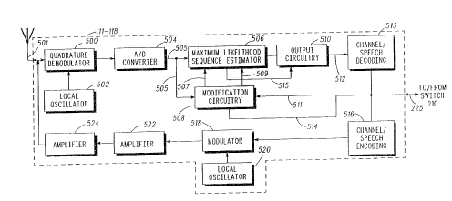
FIG. 5 generally depicts) in block diagram form) base
stations 111-118 which may beneficially implement dynamic
2 ~ channel assignment in accordance with the invention. Signals
C1-C3 transmitted on a common carrierduring a common time
slot (such as that depicted in FIG. 4A) are received by antenna
501. The signal, which contains data from C1-C3) enters
quadrature demodulator 500 which demodulates the burst signal
3 0 into I and Q components. At this point) the quadrature
demodulator is unaware that the burst contains three separate
transmissions C1-C3; it simply demodulates whatever data is
within a particular time slot. The demodulated data is sent to
ADD converter 504 which converts the demodulated I and Q
.'~O 93/11627 P~t'/US92/103~'."
9
2 s.~(~~f~~.
components into a corresponding digital signal 505. The digital
signal 505 exiting A/D converter 504 is input into both a
maximum likelihood sequence estimator 506 (MLSE) and
modification circuitry 508. MLSE 506 and modification circuitry
are used to essentially reconstruct the digital signal 505. After
reconstruction, the reconstructed signal is output from MLSE
506 into output circuitry 510. A signal 512 exiting ouxput
circuitry 510 enters a channel/speech decoding 513 block where
the signal 512 is decoded into the proper voice data. Also output
1 0 from output circuitry 510 is a signal 5I1 which is fed into
modification circuitry 5d8. Finall5~, exiting modification
circuitry 508 is a signal 514 which represents the signal quality
value eventually transferred to switch 210 for decision making
purposes.
1 5 FIG. 6 illustrates in greater detail operation of MLSE 506)
modification circuitry 508) and output circuitry 510. Digital
signal 5Q5 entering modification circuitry 508 represents
digitized values of the demodulated I and ~ signals (ID and QD).
Signals In and faD are input into correlation circuitry 612) as is
? 0 the appropriate predetermined mid-amble which is stored in
reference store 614. Correlation circuitry 612 then correlates the
mid-amble of signals ID and Q~ to the predetermined mid-
amble. The output from correlation circuitry 612 is a correlation
signal C(t) which essentially depicts, in time) the correlation
2 > performed by correlation by circuitry 612. The magnitude of
correlation signal C(t) is defined by the equation:
c(L) I ---- I~,. + (2~~
3 U where IDN and QDN are the small nth sample of ID and QD
respectively. Synchronization circuitry 610 provides
synchronization to correlations signal C(t) which is then fed to
tap modification block 608. Output from tap modification block
608 is a modified channel impulse response 507, which contains
WO 93/l 1627 ~ ~ ~ ~ i~ ~ ~. 1 0 PCT/US92/103: '~-....
the required taps to construct match filter 600. Also, output from
tap modification block 608 is a signal which enters pre-MLSE
processing hlock 616. Signal 509 exiting pre-MLSE processing
block 616 enters the MLSE 506 and is input into the Viterbi
algorithm 606 (VA) block.
Operation of MLSE 506 is as follows. A digital signal 505
which again is represented by In and QD, is input into matched
filter 600. Matched filter 600 is an adaptive filter and is supplied
with coefficients which are functions of the modified channel
1 0 impulse response 507. Matched filter 600 generates a signal
which is supplied to complex to real converter 602, which in turn
generates a real signal which is supplied to selective bit inverter
604. Bit inverter 604 generates a non-inverted output signal 515
which is supplied to Viterbi algorithm block 606. Again, Viterbi
1 ~ algorithm block 606 is supplied with coefficients which are
functions of the modified channel impulse response on line 509.
The Viterbi algorithm 606 forms a trellis operative to
estimate sequences of data responsive to application of the signal
on line 515. The estimated sequences are generated and supplied
2 0 to bit mapper 620. Bit mapper 620 is operative to convert the
binary-value data stream supplied into arithmetic values (i.e.,
positive and negative one values). The arithmetic data stream
formed by bit mapper 620 is generated on line 622 and is supplied
to filter 630 which is comprised of a 9-tap real FIR filter. Filter
? 5 630 is supplied with real coefficients which are functions of the
modified channel impulse response. The coefficients axe
supplied on line 626, are converted by converter 624 to be in real
form and are supplied to filter 630 on line 631. Again, the
coefficients of the center tap of filter 630 is of a value of zero. (The
3 0 characteristics of filter 640 are modified to compensate for the
effects of matched filter 600.)
The arithmetic data stream generated on line 622 is
additionally supplied to filter 632 which is also a 9-tap real FIR
filter having coefficients which are a function of the modified
'~O 93/11627 1 1 PCf'/L~S92/103~-
channel impulse response. Filter 632 synthesizes a channel i:~
which a11 mufti-path signal components are present. Ar.~:
application of the data stream permits synthesis of transmission
of the signal on a transmission channel. The inverse of the
signal formed by filter 632 is supplied to summer 633a
Summers 635 and 633 additionally are supplied with the ,
non-inverted signal generated b;y bit inverter 604 which is
suitably delayed in time by delay element 628. Line 515
interconnects bit inverter 604 snd delay element 628, and delay
1 0 element 628 generates a delayed, non-negative signal on line 62?
which is supplied to summers 635 arid 633. The output of
summer 633 is an error signal, x;, and is supplied to block 634
which computes a sample variance of the input signal. The
sample variance is calculated according to the equation
1 ~ illustrated within block 634. The calculated sample variance is
supplied to block 626, where the sample variance is further
scaled by the factor 1/Sro. Srp is the zero lag) auto correlation of
the matched filter coefficients; additionally) Sra is the
interproduct of the complez vector of matched filter coefficients
2 0 with itself. The scaled) sampled variance calculated at block 636
is supplied to modification circuitry 508 via line 511. The scaled
sample variance on line 511 represents the noise plus distortion
in the received signal.
Referring to modification circuitry 508, output from pre
2 5 MLSE processing block 616 is input into block 618 which
calculates the square of the energy of the demodulated and
correlated burst. Output from block 618 is input into a divider 613
which divides the noise plus distortion of the received signal by
th.v -uare of the energy produced by block 618. Output from the
3 0 di~ :~ is thus the signal quality value transferred to switch 210
an~, ..sed for decision making.
The signal quality value measured by base-stations 111-
118, depicted in FIG. 4C, and shown by output signal 514 in FIG.
is given by
WO 93/11627 PCT/US92i103= ~~
12
~2/ E2
where) in the preferred embodiment, c~2 is a measure of the noise
plus distortion in the received signal, and E2 is a measure of the
energy in the signal squared. The quantity a=/ E2 is correlated
strongly to the number of errors in the burst) and is more
efFective than either a2 or 1/E2 taken alone.
The noise plus distortion value a2 is corrupted from the
1 0 ISI-canceller filter outputs. Where each hit detected by the IYILSE
b06 of the base-stations 111-118 has associated with it an ISI
canceller value, x;
2-
i
Q ~~ X /2
1
1J
The E2 term can be derived from the
correlation/synchronization part of the receiver where samples
are taken of the correlation with the stored reference. These
samples are taken at T or T/2 spaced intervals, where T is a
2 0 received symbol time. For example, if there were nine such
sampling points, the various sets of nine points would be tried
until their sum is a maximum. The samples represent samples
Py~ (n-'~) where y(m) is the received signal, z(m) is the stored
reference and n and m are indices to the sampled functions. The
2 ~ value 't is the relative shift between them when a particular
cancelation value is computed. E, or the burst energy value is
taken as
9 \
E = W ~~ PyZ O-'~)
i
VO 93/I 16Z7 1 8 PCTlUS92/103~'
Of course, the number of sampled points on Pyz (n'~) need not be
restricted to 9. The burst energy is then squared for use in the ,
signal quality value measure.
After each base-station receiving the transmissions
determines the signal quality value) the message of FIG. 4C can
be transferred to the switch 210. When at the switch 210, the
information from the message in FIG. 4C is stored into a table as
depicted in FIG, 7. The steps the switch 210 undergoes to
perform dynamic channel allocation in accordance with the
1 0 invention are depicted in FIG. 8. At step 802, the switch 210
receives signal reports from each base-station receiver for each
carrier and timeslot. The switch 210 identifies at 804 a user
(subscriber) for each reception; subscribers are identified by
subscriber ID, carrier number and timeslot numbex. The switch
1 ~ then stores at 806 each reception for a subscriber in the
subscriber's table and saves at 808 the data from each reception
in the table which had the highest quality rating (highest signal
quality value). The switch 210 notes at 810 which base-station
was the receiver for each user and assigns at 812 all outbound
2 0 (downlink) transmissions with quality values above a
predetermined threshold to the base-station which received the
corresponding signal report. At step 814, the switch 210 finds the
strongest signal quality value for each subscriber with outbound
transmissions not yet assigned (signal quality value not above
'' ~ the predetermined threshold). The switch 210 then finds at 816 a
second base-station for each signal report having a signal quality
value below the predetermined threshold and searches at 818 for
base-stations which also stored this reception. The switch ti.cvn
routes at 820 those outbound transmissions with signal quality
3 0 values below the predetermined threshold to these base-stations
and waits at 822 for the next reception.
When the same uplirik carrier and timeslot are used by
two (or more) different subscribers Z00, 120, 121, the packets of
information received by base-station 111 will have poor reception
WO 93/11627 1 4 P~:T/US92/1p3 -_.
c~.~~.~~~~~
quality due to co-channel interference. In fact, several of the bits
in the packet, possibly even most of the bits) may be in error.
However) there will be some base-stations within the system .
which, do to geographic and propagation effects) will receive that
transmitted packet with an acceptable level of quality or a level of ,
quality of which, when combined with techniques 6uch as coding
and interleaving) ultimately produce acceptable results.
Regardless of the quality, however, the bits that are detected from
the packet along with a, signal quality value determined by base-
1 0 stations 111-Z18 receiving the uplink message, are sent to switch
210. Switch 210 scans all the individual carriers (frequencies)
allocated to the system and analyzes the quality reports from all
base-stations 11Z-118 which have received the uplink message on
a particular carrier and timeslot, and accepts an individual
1 ~ packet on a carrier only from the base-statian that gives the best
quality report for that particular packet.
In conventional cellular systems, one base-station is
typically a dedicated packet receiving point for one particular
subscriber unit) for example) base-station 111 for subscriber unit
2 0 100. The dedicated base-station monitors the quality of
transmission by the subscriber unit 100 and notifies target base-
stations when a handoff is required. The target base-stations
measure the transmission quality of the subscriber unit 100,
notify the switch 210) and the switch tells a chosen target base-
2 > station to tune to a new frequency for communication. The
micro-cellular system, in accordance with the invention, is
different from conventional cellular systems in that any base-
station can be the receiving point for a particular subscriber
within a first subset of frequencies, and allocation of this
3 0 "receiving" base-stations could actually be made to change in the
extreme case of every single time a new packet is transmitted by
a subscriber unit 100. As a subscriber unit 100 moves
throughout a micro-cell coverage area, all base-stations within
the coverage area measure the transmission of the subscriber
'~'O 93l11627 1 5 PC.'1'/US921103.~'. ,
unit I00 and report the measurement back tc ;.he switch 210. The
switch 210 assesses the relative quality measurements and
assigns the base-station reporting the best relative quality to
receive the uplink transmission of the subscriber unit z00. In
addition) the switch 210 may decide to maintain downlink
transmission on the original base-station so that the chosen
base-station need not transmit a downlink signal to the
subscriber unit 100. 13y dynamically separating the uplink path
from the downlink path, the micro-cellular radiotelephone
1 0 system compensates for co-channel interference by constantly
receiving the best uplink transmission made by the subscriber
I00. In addition) the system allows for reduced control
messaging, which in turn increases the speed at which
allocation can be performed.
1 5 Important to note is that changing of base-6tations
receiving the transmitted packet is transparent to the subscriber
unit 100; no control signalling need be sent to the subscriber u.-~' .
100 to accomplish this dynamic base-station recei -
assignment. Consequently, as a subscriber unit 100 mows
2 0 throughout the micro-cellular coverage area, each of its
transmissions may actually be received by different base-stations
without any signalling, and hence without its knowledge.
Consequently) there is no handoff as required in conventional
systems.
2 ~ If the system is allowed to dynamically assign
communication to any channel in the system, channels will, in a
sense, wander from cell-to-cell or non-traditional channel pairs
(against tradaional reuse patterns) will be formed. This
"flexibility" in the system could potentially lead to bunching of
3 0 channels in unintended areas. To reduce this bunching, the
system should be capable of dynamically re-configuring itself
into an appropriate reuse pattern. Factors the system must take
into account to re-configure itself might include: control vs
traffic channel bunching) physical cell vs logical cell
WO 93/11627 ~~,p~ 1 6 pCT/US92/103
'~J ~.
configurations, movable channel sets vs stationary channel sets,
lists of unusable channels in each cell dynamically updated) list
of potential handover channels in each cell dynamically updated,
etc. In this fashion, the system is never restricted to a particular
reuse pattern as in traditional systems, thus channel use, and
consequently subscriber capacity) are continuously optimized.
When down-link transmission is required, switch 210
decides which base-station 111-118 will transmit to a particular
subscriber 100, 120, 121. The signal quality value measured on
1 0 the uplink message by any base-station receiving the packet is
stored) and switch 210 decides which base-station 111-118 should
transmit the downlink packet to subscriber 100. If any of the
base-stations which received the packet report a signal quality
value above a predetermined threshold, that particular base-
1 5 station is the prime base-station for transmission on the
downlink path to subscriber 100. For example, if subscriber's 100
and 120 transmission was received by base-stations I11, 1I2, 117
on a common carrier during a common timeslot, those base-
stations 111, I12, 117 would measure a packet quality value of the
2 0 transmission and report it to switch 210. If one of the quality
values reported by a base-station, say base-station 111, were above
a particular) predetermined threshold for subscriber 100) then
base-station 111 would be the prime base-station for transmission
back to subscriber 100. If base-station 111 were not available,
then the next base-station with the next highest quality value,
say base-station 112, is chosen. This iterative process would
continue until a base-station is available for downlink
transmission. If, on the other hand, none of the quality values
reported by base-stations 111) 112, I17, were above the
3 0 predetermined threshold, then the downlink transmission
would preferably take place from two base-stations. In the
preferred embodiment, the two base-stations would be the two
base-stations which have the highest measured packet quality
values for a particular subscriber 100. This, in effect, produces a
"O 93/1162i
17
PCT/ L S92/ 1034'
downlink transmit diversity effect. The two chosen base-stations
may, in fact) be separated by quite a distance, and this may tend
to generate statistically independent downlink transmission
paths and produce ineffective diversity at the particular
subscriber 100. To accommodate the case where a large number
of subscribers are served by the diversity effect, the system is
likely to require more) perhaps significantly more, outbound
channels than the number of subscribers to be served.
In the preferred embodiment, a given coverage area is
1 0 covered by a large number of base-stations, each of which ideally
is capable of receiving and transmitting on any one of the
frequencies allocated to the system. FIG. 1 only depicts a small
percentage of base-stations 111-118 which are incorporated in the
system; in fact, each cell within the system has its own base
1 j station. The entire collection of those base-stations within the
system is connected to switch 210 of FIG. 2) which may accept
information (signal quality values, subscriber ID) etc.) from each
of the various base-stations and make a decision. Furthermore,
switch 210 can route all downlink traffic to be transmitted from
2 0 any base-station to any particular subscriber unit. Thus, all
traffic for a coverage area passes through switch 210. It may be
possible to have several switches 210 in communication with one
another instead of a single one, if the coverage area is large.
Tn an alternate embodiment, the micro-cells may be a
~ subset of a larger, umbrella cell. For example) referring to FIG.
1, cells 103, 108 could have micro-cell characteristics herein
described while cell 102 could have traditional cellular
characteristics, To avoid co-channel interference, the micro
cells are allotted a first subset of channels within the set of
(1 allocated channels while the umbrella cell is allotted a second
subset of channels within the same set of allocated channels.
From FIG. I) micro-cells 103 and 108 have a common coverage
area (the shaded section of FTG. 1) with the predetermined
coverage area of umbrella cell 102. If a subscriber unit 100 were
WO 93l11627 ~'~ PC'1'/US9?l103.;,..,
1s
now moving within that common coverage area, base-stations
1I2, II3, and 118 would measure the uplink transmission of the
subscriber unit I00. A switch 210 (shown in FIG. 2) would
assess the measured relative quality of the uplink transmission
and assign communication accordingly. If the subscriber unit
100 were initially communicating to base-station 118, a first
micro-cell base-station, the switch would assign base-station 113,
a second micro-cell base-station) to receive the uplink N
transmission if it reported the best relative qualit~~
1 0 measurement. Within the micro-cell system) base-station 118
could maintain downlink communication to the subscriber unit
100 while base-station 113 would maintain uplinh
communication to the subscriber unit I00. This would not result
in a channel change when viewed firom the prospective of the
1 ~ subscriber unit 100. However, if base-station 112 reported the
best relative quality measurement, traditional handoff
techniques would be required since the micro-cells and umbrella
cell have different channel partitioning for co-channel
mitigation purposes. In this case, both uplink and downlink
2 0 communication are handed off to base-station 112 in umbrella
cell 102, the hand-off occurnng from a first channel within the
first subset of channels to a second channel within the second
subset of channels.
The system idea is compatible with FDMA/TDMA or
2 ~ CDMA-type systems. In the case of FDMA and TDMA, the
digital information to be transmitted will be framed and the
individual subscribers will be identified by some unique bit
pattern within each frame. This might be a particular
synchronization sequence assigned to an individual subscriber
3 0 100) 120 or it might be the synchronization sequence in
combination with another custom sequence within the framed
information. In the case of CDMA, the individual subscribers
I00, 120 may be identified by their spreading codes. In any case,
it is these identifiers which allow system controller 215 to decide
-Vp 93l1162'7 1 9 PCT/US92/103-1'
which quality reports from which base-stations 111-117 to
compare the quality information of in order to make a
determination of how to pass the information throughout the
system. Therefore, it is necessary for base-stations 111-I17 to be
able to recognize) in the case of FDIviA or TDMA, all the possible
identifiers (synchronization codes) possible plus some additional
identifying bits. In the case of CDI'vIA, it is necessary for base-
stations 111-117 to recognize all of the individual spreading
codes. Subscribers 100,120, however) may be made simpler since
1 0 'they do not sort out multiple transmissions with different
identifiers; everything intended for a given subscriber 100) 120
will be transmitted with its own identifier or its own spreading
code. Therefore, subscriber 100) 120 need only look at an expected
frequency or set of frequencies at an expected time for an
1 5 expected identifier.