Note: Descriptions are shown in the official language in which they were submitted.
WO93/21717 2 1 ~ 3 8 1 5 PCT/US92/05153
RADIO FREQUENCY BROADCA8TING ~ S AND METHODS
USING TWO LOW-COST GEOS~N~KONOU8 SATELLITES
BACRGROUND OF THE INVENTIO~
Over the past several years, proposals have been made in
the United States at the Federal Communications Commission
(FCC) and, internationally, at the International
Telecommunications Union (ITU) to broadcast radio programs
from geosynchronous satellites to receivers in mobile
platforms (e.g., automobiles) and in other transportable and
fixed environments. Since geosynchronous satellites are
located in near-equatorial orbits approximately 42,300
kilometers from the earth's surface, such satellites appear
stationary to an observer on the ground. The satellite views
roughly one-third of the earth's surface below it, which
allows radio broadcast coverage of such a large area or, by
using directional antennas on the satellite, a sub-area such
as a particular country. This potential national coverage
area of many tens of millions of square kilometers for
providing radio service throughout the continental United
States (or other country/region) is the main feature of
satellite radio broadcasting, since normal terrestrial AM/FM
,radio stations typically cover a much smaller area.
Radio broadcasting from satellites involves use of
special receivers in mobile or fixed platforms because of
technical implementation and frequency allocation/interference
requirements. Consequently, proposals for building such
systems have generally used UHF frequencies in the range of
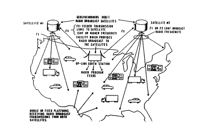
about 300 to about 3,000 MHz. Fig. 1 shows a typical
satellite radio broadcasting system. Additional satellites
--1-- .
WO93/21717 ~ 1 0 ~ 8 1 5 PCT/US92/~1~3
can be used with the satellite system shown in Fig. l for
providing redundancy, additional channels or both. Fig. l
shows the most important transmission path, the path from the
satellite to the mobile or fixed platforms. Since a mobile
platform requires an antenna which can receive satellite
signals from all azimuths and most elevation angles, the
mobile platform antenna gain must be low (e.g. 2-4 dBi gain is
typical). For this reason, the satellite must radiate large
amounts of radio frequency transmitter power so that the
mobile platform receiver can receive an adequate signal level.
In addition to the need for a high power transmitter in
the satellite is the need for extra transmitter power, called
"transmission margin", to overcome multipath fading and
attenuation from foliage. Multipath fading occurs where a
signal from a satellite is received over two or more paths by
a mobile platform receiver. One path is the direct line-of-
sight or desired path. On other paths, the signal from the
satellite is first reflected from the ground, buildings, or
trucks, and then received by a mobile platform receiver, as
Fig. 2 shows. These other paths are interfering in amounts
that depend on factors such as losses incurred during
reflection.
Among the methods for reducing multipath fading in radio
systems, are the following:
l. Providing a second path for a desired signal between
a transmitter and a receiver that is physically
different from the first path for the signal. This
is called space diversity, and is effective where
--2
wo 93r21717 21 U 3 81 5 PCT/US92/05153
only one of the two paths is strongly affected by
multipath fading at any instant;
2. Providing a second transmission frequency for a
desired signal between a transmitter and a receiver.
This is called frequency diversity, and is effective
where only one of the two frequencies is strongly
affected by multipath fading at any instant; and
3. Providing signal modulation resistant to multipath
fading such as spread spectrum. This method is
effective where some resistance results from the
large modulated frequency bandwidth used, and some
resistance results from the receiver's rejection of
an undesired signal's spreading code.
The transmission margin necessary to overcome multipath
fading or attenuation from foliage has been both measured and
estimated by experts to be in the range of about 9 to about 12
dB for satellite radio broadcast systems operating at UHF
frequencies. Fortunately, multipath and attenuation from
foliage seldom occur simultaneously. However, the need for 9-
12 dB transmission margin means that satellite transmitter
power must be increased by a factor of 8 to 12 over its
initially high level. Radio broadcasting satellites operating
at such power levels would be extremely large, complex and
costly. To date, no commercial system of this kind is in use
because of this high cost.
The systems and methods of this invention overcome these
problems, by sending the same radio broadcast signals
substantially simultaneously through two or more
WO93/21717 2 1 ~ 3 8 1 5 PCT/US92/~153
geosynchronous satellite sources separated by a sufficient
number of degrees of orbital arc to minimize the effects of
multipath fading and foliage attenuation, as Fig. 3 shows.
A receiver on a mobile or fixed platform receives the two
signals through two physically distinct paths in space
diversity methods, and selects the stronger signal, or
combines the two signals. The signals can be at the same
radio frequency using a modulation resistant to multipath
interference, or at a different radio frequency, with or
without a modulation resistant to multipath. Foliage
attenuation is minimized because trees and other foliage are
seldom in the line-of-sight to both satellites at the same
time.
In preferred embodiments, these systems and methods
provide radio broadcasts from geosynchronous satellites with
one-eighth or less the power needed with a single satellite.
Since satellite cost is directly proportional to satellite
transmitting power, the radio broadcast satellite system of
this invention uses satellites about one-eighth or less as
costly and as heavy as single satellite systems. The reduced
satellite mass also permits the use of a lower capability,
lower cost launch vehicle. Even if two launch vehicles are
needed, the satellite portions of the subject system are still
only about 25% as costly as a single satellite transmission
system.
The subject system substantially improves reception
quality by eliminating many blockage outages. Blockage
outages occur when physical objects such as buildings or hills
W093/21717 21 0 3 8 1 5 PCT/US92/05153
lie in the line-of-sight between the satellite and the
receiver. As Fig. 4 shows, such blockage seldom occurs
simultaneously on both satellite paths. Fig. 4 also shows
that signal attenuation from foliage is minimized, because
such attenuation results from partial signal blockage.
8UMNARY OF THE INVENTION
This invention relates to a system of two or more
satellites moving in spatially separated positions on
substantially the same geosynchronous orbit, each sending or
relaying, substantially simultaneously, preferably at UHF
frequencies in the range of about 300 to about 3,000 MHz, the
same radio broadcast signal to receivers at or near the
earth's surface. The spatial separation of the satellites is
sufficient to minimize multipath fading, foliage attenuation,
or both. Preferably, the separation between any two
satellites is in the range of about 25- to about 50 . These
signals are preferably digitally modulated for high fidelity,
but may also be analog.
BRIEF DESCRIPTION OF THE DRAWINGS
The systems and methods of this invention can better be
understood by reference to the drawings, in which:
Fig. l shows a UHF radio broadcast satellite system
utilizing a single satellite source;
Fig. 2 shows multipath fading that occurs in UHF radio
broadcasting from satellites;
Fig. 3 shows an embodiment of the UHF radio frequency
broadcasting system of this invention utilizing two spatially
separated satellite sources on substantially the same
WO93/21717 PCT/US92/05153
2103~15
geosynchronous orbit;
Fig. 4 illustrates the reductions in total and partial
blockage outages attainable with the two-satellite system
embodiment shown in Fig. 3;
Fig. 5 shows a single correlator-type co-frequency
satellite radio broadcast receiver for use with the two-
satellite system embodiment shown in Figs. 3 and 4;
Fig. 6 shows a dual correlator-type co-frequency
satellite radio broadcast receiver for use with the two-
satellite system embodiment shown in Figs. 3 and 4; and
Fig. 7 shows a dual-frequency satellite radio broadcast
receiver for use with the two-satellite broadcast system
embodiment shown in Figs. 3 and 4.
DEæCRIPTION OF THE PREFERRED EMBODIMENT~
In the co-frequency embodiments of Figs. 5 and 6, two
satellites in substantially the same geosynchronous orbit send
or relay substantially the same signal at substantially the
same radio frequency. As a result, the receiver for the radio
signals can be simple, and low in cost. The modulation method
used preferably resists multipath interference and prevents
mutual self-interference that would result in signal jamming.
Methods such as spread spectrum modulation (e.g., direct
sequence or frequency hopping) are preferably used to achieve
Code Division Multiple Access (CDMA).
A preferred receiver for use in a mobile platform such as
a vehicle is a standard, one-channel direct sequence spread
spectrum detection device. This device is adapted to acquire
the code of the signal from any of the satellites in the
WO~3/21717 2 1 0 3 8 1 5 PCT/US92/05153
-
system. Preferably, this code is the same for the signals
from both satellites, which is accomplished by having the
satellites receive the radio signals to be transmitted to the
mobile platform receiver from an up-link station on the
S earth's surface. Such an up-link station could delay one of
- the two codes in time to permit faster acquisition. In the
mobile receiver, when the signal level drops a fixed,
predetermined amount below a threshold value, such as an
amount greater than 2 dB, a code loop is opened, and re-
acquisition is performed on any signal stronger than the
threshold value, as Fig. 5 shows in block diagram form. In
Fig. 5, the antenna receives the radio frequency signals from
each of the two satellites. The signals are amplified by the
radio frequency amplifier. The signals are changed from radio
frequency to an intermediate frequency (IF) by the down
converter. The specific intermediate frequency is chosen by
the frequency of the local oscillator. One of the two signals
is acquired and detected by the spread spectrum demodulator on
a random basis and the other signal ignored. The signal level
of the detected signal is sent to the Signal Level Memory and
Threshold Comparator. The detected signal is then sent to an
audio amplifier and loudspeakers for listening. The Signal
Level Memory continuously receives the signal level of the
detected signal and compares it with the previously sent
values of signal level. When the current value of signal
level falls a certain amount (i.e., to a preset threshold),
the spread spectrum demodulator is forced to re-acquire a
signal, and attempts to do so until a signal is re-acquired
WO g3/21717 2 1~0 3 8 1 5 PCT/US92/05153
whose level is greater than the threshold level.
Alternatively, the receiver in the mobile platform can
have common antenna, radio and intermediate frequency (IF)
equipment. The IF feeds two correlators, each namely an
independent spread spectrum code acquisition circuit and a
detection circuit, as shown in Fig. 6.
In Fig. 6, the antenna receives the radio frequency
signal from each of the two satellites. The signals are
amplified by the radio frequency amplifier. The signals are
changed from radio frequency to an intermediate frequency (IF)
by the down converter. The specific intermediate frequency is
chosen by the frequency of the local oscillator. The down
converter output is split in half by the splitter, and
presented to each spread spectrum demodulator. Each spread
spectrum demodulator acquires and detects one of the two
signals. The two signals can be recognized by either using a
different code sequence for each signal, or by having an a
priori time offset between the two signals' identical code
sequence. Each spread spectrum demodulator sends the detected
signal to either the Amplitude Sensor Switch, which outputs
the stronger (higher level) one to an audio amplifier and
loudspeakers for listening, or to the Phase Corrector and
Adder, which shifts the signals so they are in phase with each
other and then sums them. The sum is outpu$ted to an audio
amplifier and loudspeakers for listening. Alternatively, the
phase correction can be accomplished in the Spread Spectrum
Demodulators. The codes of the signals from the satellites
can be substantially identical, but offset in time or
WO93/21717 2 1 0 3 8 1 5 PCT/US92/~153
orthogonal to one another, as are Gold codes. Each of the
detected signals is derived from the correlators. The signals
can then be selected individually, or combined with one
another to produce a single, summed output signal.
The receiver preferably outputs a signal by one of two
methods. The simpler method compares the amplitudes of the
signals from the two satellite sources, and chooses the
stronger signal for output. Alternatively, the phases of the
two signals are adjusted until they are identical to one
another. The two signals are then summed to produce an output
signal. This method avoids switching the receiver from one
signal to another, and provides better quality signals when
the transmission paths of the two signals are unaffected, or
are only partially attenuated by multipath fading or foliage.
The previously mentioned phase adjustments are necessary
because, although both satellite sources send substantially
the same signal at substantially the same time, these signals
reach the mobile platform receiver with different phases since
the platforms are generally at a different distance from each
satellite.
In the dual-frequency embodiments, both satellites send
or relay substantially the same broadcast signal, but at two
substantially different frequencies. These embodiments
achieve less multipath fading because both space and frequency
diversity are attained simultaneously. These embodiments
further permit the use of multipath resistant modulation.
However, the receiver is more complex. As Fig. 7 shows, such
a receiver includes two down converters, intermediate
_g _
21D3815
WO93/21717 PCT/US92/05153
frequency amplifiers and demodulator circuits. In Fig. 7, the
antenna receives the radio frequency signal from each of the
two satellites. The signals are amplified by the radio
frequency amplifier. The radio frequency amplifier output is
split in half by the Splitter and presented to each down
converter. The signals are changed from radio frequency to an
intermediate frequency (IF) by the down converters. The local
oscillators are set to the proper frequencies so that the
signal frequencies Fl and F2 are converted to the same IF. The
IF from the down converters feeds the demodulators. The
demodulators remove the signal modulation, and send the
detected signals to either the Amplitude Sensor Switch, which
outputs the stronger (higher level) one to an audio amplifier
and loudspeakers for listening, or to the Phase Corrector and
Adder, which shifts the signals so they are in phase with each
other and then sums them. The sum is outputted to an audio
amplifier and loudspeakers for listening. Alternatively, the
phase correction can be accomplished in the demodulators.
Dual-frequency embodiments can be as shown in Fig. 7, or
can be of a type which switches rapidly between the
frequencies of the two signals, or can utilize digital signal
processing. The output signals from the receiver can be
selected by comparing the amplitudes of the two input signals,
and using the stronger signal, or the input signals can be
adjusted to the same phase and summed to produce an output
signal.
--10--