Note: Descriptions are shown in the official language in which they were submitted.
WO 92/21185 PCf/US91/03612
~~~J~~~
ISDN Interfacing of Personal Computers
Technical Field
The invention is directed generally to Integrated
Services Digital Networks (ISDN), and more particularly
to apparatus for enabling access to an ISDN ,line by a
personal computer, or local area network.
Background Art
ISDN is a relatively newly developed and emerging
field of telecommunications which integrates computer
and communications technologies to provide; worldwide,
a common, all-digital network. This is based, in part,
on standardizing the structure of digital protocols
developed by the International Telegraph and Telephone
Consultative Committee (CCITT). Despite the
implementation of multiple networks within national
boundaries, from a user's point of view there is a
single, uniformly accessible, worldwide network capable
of handling a broad range of telephone, data and other
conventional and enhanced services.
A complete description of the architecture of ISDN
is beyond the scope of this specification. For
details, and for an extensive bibliography of
references on ISDN, see Stallings, ISDN~.An
Introduction, MacMillan Publishing Company, 1989,
An ISDN is structured by architecture closely
following the OSI Seven Layer Reference Model. Within
the framework of ISDN, the network provides services
_.. . . _ ~.. , , .- , :~ , ,~, ., . ,. ;; .,~....,. ..... _. ... , e_..:. ,.
.
v.:~ ,.'~k.... ~.. ' : , . . : . w ~;.~ , . ; , , . . ~ , , . ~ ~; . ...
WO 92/21185 PCT/US91/03612
2
~s~~~~~
and the user accesses the services through the user-
network interface. A "channel" represents a specified
portion of the information carrying capacity of an '
interface. Channels are classified by two types, Basic
Rate ISDN (BRI) and Primary Rate ISDN (PRI). BRI
delivers two B-channels, each having a capacity of
64Kbps, capable of transmitting voice and data
simultaneously. A l6Kbps D-channel transmits call
control messages and user packet data. PRI provides
twenty three B-channels of 64Kbps capacity each for
carrying voice, circuit switched data or packet data.
The D-channel is a 64Kbps signaling channel. The B and
D channels are logically multiplexed together at Layer
1 of the OSI Reference Model.
Figure 1 depicts the conventional ISDN
interfaces. At the customer premises, an
"intelligent" device, such as a digital PBX terminal
controller or Local Area Network (LAN), can be
connected to an ISDN terminal TE, such as a voice or
data terminal, which is connected to a Network
Termination (NT1). Non-ISDN terminals TE may be
connected to a Network Termination (NT2) and a Terminal
Adapter TA. The NT2 in turn is connected over an "S/T-
Interface", which is a four-wire bus, to a termination
NTl that performs functions such as signal conversion
and maintenance of the electrical characteristics of
the loop.
At the local loop, a two-wire bus, termed the "U
Interface", or "Loop", interconnects NT1 and a Loop
Termination (LT) at the central office. Finally, the
"U-Interface" is a bus between the local loop at the '
carrier end and exchange switching equipment. Details
of this architecture are provided in ISDN: An Overview,
Data Pro Research, Concepts & Technologies, MT 20-365;
WO 92/21185 PGT/US91/03612
~:~c~~~~~~
pp 101-110, published by McGraw Hill, Incorporated
(December 1988).
For connecting a personal computer to a
conventional telephone line, a modem is required to
convert outgoing digital signals generated by the
computer into analog signals to be carried by the line,
and to convert incoming analog signals to digital
signals. Because an ISDN line is a digital network,
however, no modem is required to interface a computer
with the line; a computer is able to be connected to
the ISDN line directly.
On the other hand, any interface between a
computer and the ISDN must carry out conversion between
the protocol stack implemented by the computer and ISDN
protocol. The present invention provides gateway
functions between personal computers and ISDN lines in
a manner supporting existing communication protocols.
Are interface may operate at any of several layers
of the OSI model. A "repeater" is an interfa~~e
operating at the physical link layer. A "bridge"
interconnects networks at the data-link layer, and a
"routes" functions at the network layer. "Gateways"
'handle higher-level internetwork protocols. This
terminology is not universal; for example, "gateway"
sometimes is used to describe a "routes", and it
occasionally is used to.refer to a "bridge". The term
"gat~way" will be used hereinafter to refer generically
to any of these devices.
An ISDN gateway must satisfy several functions. It -
must be capable of transferring files on the ISDN at a
very high rate of data trapsfer. The gateway
furthermore must be "transparent" to the user, that is,
the user of a computer should not be able to
distinguish between data transfer among local
WO 92/21185 PCf/US91/03612
4
~lU~b~~~
resources and remote data transfer over the ISDN.
Furthermore, standard communications software available
for personal computers should be application to
communications on the ISDN. Bandwidth utilization of
the Network must be efficient and independent of the
amount of~traffic encountered.
Currently, gateway functions for personal
computers are carried out by central office equipment
in accordance with customer specifications. A need
~ exists to establish gateway functions with equipment
installed' at customer premises to enable computers to
be universally connectable to the ISDN. A further need
exists to establish gateway functions having the
characteristics described in the preceding paragraph.
Disclosure of the Invention
Accordingly, one object of the invention is to
interface personal computers to an ISDN line.,
Another object of the invention is to interconnect
personal computers to an ISDN line using customer
premises equipment (CPE) carrying out gateway
functions.
A further object is to interface personal
computers and the ISDN line for very high rate of file
transfer ~to or from a remote. location. '
A ' still further ob ject~ of the invention is to
carry out communications between computers
transparently over an ISDN line, i.e., so that no
difference between accessing local or remote data is
visible to the user:
Another object of the invention is to interface '
personal computers to the ISDN line, enabling users to
access the line while using resident software '
applications. w
WO 92/21185 5 ~ ~ ~ ~ ~ ~ ~~ PGTlUS91/03612
Still another object is to interface a local area
network of personal computers to an ISDN line.
A further object is to enable personal computers
using standard communications software to transfer data
over ISDN lines.
The above and other objects are satisfied in
accordance with one aspect of the invention by a
gateway provided at the customer premises, translating
protocols used on dissimilar networks and carrying out
other network interfacing functions. In accordance with
a preferred embodiment of the invention, the gateway
comprises one or more circuit modules (ISDN LINE CARD,
SYSTEM MASTER CARD, etc.) resident with a host
computer, interfacing the host to the ISDN line. The
circuit module (ISDN LINE CARD) includes means for
performing protocol conversion of data flowing between
the host and ISDN line through the gateway, means far
establishing input and output destination queues, means
for measuring traffic flow at each input and output
destination queue during a particular time interval,
and means for dynamically allocating channels on the
ISDN line in response to traffic.
Preferably, the circuit module also includes a
system master (SYSTEM MASTER CARD) for managing the
configuration of the gateway and for accessing other
gateways on the ISDN line. A communication mode
adaptor (CMA) incorporated in the module provides~modem
dial-up protocols, and an ISDN manager receives and
routes incoming data, setting up, selectively, circuit
switched and virtual circuit calls and incorporating
the aforementioned dynamic channel allocation
functions. In the preferred embodiment, the circuit
module further includes an ISDN device driver and a
WO 92/21185 PCT/US91/03612
6
~a c~
configuration control manager storing a table of
gateway operating parameters.
In accordance with another aspect of the
invention, dynamic channel allocation includes long
term channel allocation means for allocating or '
deallocating transmission channels to a particular
destination on the line depending upon data flow
traffic to that destination and upon particular channel
parameters, and short term channel allocation means.
The short term channel allocation means overrides the
long term channel allocation, means in response to
predetermined conditions for allocating or
deallocating transmission channels on the ISDN line.
In accordance with a further aspect of the
invention, the data is arranged in packets, and the
module includes means for assembling pluralities of the
packets into trains, each consisting of a predetermined
number of packets, for transmission on the ISDN line.
Preferably, the trains are compressed prior to
transmission to improve bandwidth utilization.
Still other objects and advantages of the present
invention will become readily apparent to those
skilled in this art from the following detailed
description, wherein only the preferred embodiment of
the invention are shown and described, simply by way of
illustration of the best mode contemplated of carrying
out the invention. As will be realized, the invention
is cgpable of other and different embodiments, and its
several details are capable of modifications in various
obvious respects, all without departing from the
invention. Accordingly, the drawing and description
are to be regarded as illustrative in nature, and not
as restrictive.
WO 92/21185 PGT/US91/036i2
~i~~~~4~
Brief Descrivtion of Drawings
Figure I is a simplified circuit diagram of an
Integrated Services Digital Network.
Figure 2 is a symbolic diagram showing a
conventional public circuit or packet switched network.
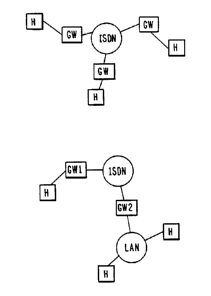
Figure 3 is a symbolic diagram showing interfacing
of personal computers to ISDN lines through ISDN
gateways in accordance with one aspect of the
invention.
Figure 4 is a symbolic diagram showing
interconnection of a remote host to an existing local
area network through an ISDN gateway, in accordance
with another aspect of the invention.
Figure 5 is a simplified block diagram showing
hardware architecture of an ISDN gateway at the
customer premises in accordance With the invention.
Figure 6 is a diagram of software architecture
incorporated in the system master card shown in Figure
5.
Figure 7 is a diagram of software architecture
showing one embodiment of a LAN line card of Figure 5.
Figure 8 is a diagram showing software
architecture incorporated in an ISDN line card shown in
Figure 5.
Figure 9 is a diagram of software architecture
incorporated in the SDLC line card shown in Figure 5.
Figure l0(a) and 10(b) are diagrams showing
mapping of software to hardware components within the
ISDN gateway of the invention.
Figure 11 is a diagram showing operation
hierarchy in the ISDN line card shown in Figures 10(a)
and 10(b).
Figure 12 is a symbolic diagram of the
WO 92/21185 PCT/US91/03612
g
~~1~3~~~t~
communication mode adapter incorporated in the ISDN
line card.
Figure 13 is a flow chart of algorithms for "
carrying out LTA channel allocation in accordance with
an aspect of the invention.
Figure 14 is a flow chart of algorithms for
selecting between LTA and STA channel allocation.
Figure 15 is a flow chart of channel processes
responding to decisions made by both the LTA and STA
channel allocation algorithms.
Figure I6 is a symbolic diagram showing
development of a virtual channel and its components.
Figure 17 is a block diagram of circuitry for
carrying out LTA channel allocation in accordance with
another aspect of the invention.
Figure 18 is a flow chart describing assembly and
compression of packet trains for transmission to a new
B-channel.
Figure l9 is a flow chart showing decompression
and resequencing of packets.
Figures 20a and 20b are diagrams respectively of a
packet and a data frame implemented in the invention.
Figure 21 depicts a train of packets in accordance
with a further aspect of the invention.
Best Mode for Practicing the Invention
1. Overview
An ISDN gateway for personal computers comprises
at least one circuit board resident in each computer
for carrying out protocol conversion and other network
interface functions . One embodiiaent of the gateway
enables any computer so equipped to be connected to an
ISDN line, as shown in Figure 3. Another embodiment
enables an ISDN line to be connected to a local area
. ._ . ,. , . . , v.: , < .
., _ . ." , . ;:,.' . , .. .- , . : , .
.._:, , ;; ' ... . . . . '~.,
WO 92/21185 PCT/US91103612
network of computers (Figure 4). To improve bandwidth
utilization of the ISDN line while transferring voice
or data, a B-channel allocation algorithm executed by
the gateway, as described in Figures 13-16 dynamically
allocates bandwidth by monitoring traffic at each
destination queue and responsively allocating or
deallocating virtual B-channels. Bandwidth utilization
is optimized by packaging data packets into trains,
shown in Figure 21, that are transmitted to a
destination when the train is completed and upon
satisfaction of other conditions. Each train undergoes
data compression by execution of a suitable compression
algorithm shown in Figure 18 followed by restoration in
accordance with an algorithm of Figure 19.
2. Network Architecture
Referring to Figure 5, an ISDN gateway 100 of a
type shown in Figures 3 and 4 , in accordance with the
invention, .comprises a "module" having four hardware
elements 102, 104, 106, 108 interconnected by a common
bus 110. The elements 102-108 preferably .comprise
individual circuit cards, although some or all of the
el~ments may be incorporated in a single circuit board.
The board or boards preferably reside within a personal
computer but alternatively may reside outside the
computer as an "outboard" module.
Element 102 is a system master which implements
infrequent user functions; such as configuration
management and connection requests. The system master
102 furthermore functions as a standard computing
platform, emulating an IeM compatible PC or other
computer standard.
3~AN line card 104 implements firmware and hardware
for specific IEEE 802 physical and data link protocol
CA 02109634 2000-OS-24
will be required for other LAN connections, e.g., 802.5
Token Ring and 802.3 Ethernet. Details on the content
LAN line card 104 are given in U.S. Patent No.
5,442,630 granted on August 15, 1995 to Gagliardi et
5 al., entitled "ISDN Interfacing of Local Area Networks".
ISDN line card 106 comprises firmware and hardware
implementing the ISDN physical, data link layer (LAPD),
and the D-channel layer 3 protocol, and the physical
layer of the B-channel. Software incorporated in the
10 ISDN line card 106 implements train protocol and B-
channel allocation algorithms as well as data
compression algorithms to support a virtual broad band
capability of the gateway, described in U.S. Patent No.
5,463,629 granted on October 31, 1995 to Gagliardi et
al., entitled "Dynamic Channel Allocation Method and
System for Integrated Services Digital Network". SDLC
line card 108 includes firmware and hardware to
implement the SNA physical and data link (SDLC) layers.
This card is optional to the Network.
3. Software Architecture
The software architecture of system master element
102, shown in Figure 6, is configured with three layers
of software underlying the system master 102(a) in a
stack. The underlying layers comprise call request
management, configuration management and monitoring
layer 102(b), as well as layers 102(c), 102(d) for
implementing a computing platform.
In Figure 7, the software architecture of one
embodiment of a LAN line card (LLC) 104 for 802.5 Token
Ring comprises a functional layer 104(a) together with
WO 92/21185 PCT/US91/03612
m ~~.~J~;~~
a layer 104(b) comprising a host filter, receiving and
selectively processing packets addressed to the host.
Underlying layers 104(c), 104(d) in this example
implement the specific IEEE 802 physical and data link
protocol (802.5) for Token Ring.
v In Figure 8, the software architecture of the ISDN
line card 106 comprises a functional layer 106(a),
together With underlying layers 106(b)-106(f) for
carrying out the requirements of the OSI Reference
Model layers associated with ISDN. These layers
include a communication mode adapter (CMA) at layer
106(b) and protocol services at layer 106(c). Layer
106(d), IIM, carries out gateway peer protocol and
executes buffer allocation algorithms to be described
in detail later. Peer protocols, applied on B-
channels used by the gateway to implement train
packing, compression and error handling, are also
described later.
Figure 9 depicts software architecture of the SDLC
line card implementing the SNA physical and data. link
layers for carrying out inter-networking among hosts.
Mapping of software shown in Figures 6-9 to
hardware components of Figure 5 is symbolized in
Figures 10(a) and l0(b). Figure 10(a) depicts the
software architecture of the gateway configured to
interface a personal computer with the ISDN (MODEM-
TYPE) as shown in Figure 3. Within the system master
card 102, a USER software module 110 supports user
application software and protocol stack residing at
layer 7 of the OSI Reference Model. Configuration
control manager 112 of the system master monitors
bandwidth allocation and errors. The system master
card 102 manages configuration of the gateway,
providing status, billing and information tracing on
WO 92/21185 PCT/US91 /03612
. . 12
~1 ~.~~t~~~~
the use of resources in the gateway, as well as access
to internal tables used by bridging and routing gateway
services. The system master 102 further updates '
records loaded on disk into memory resident data
structures when the system is initiated. When these '
tables are updated, the disk is automatically updated
as well.
Configuration control manager 112 controls
parameters which define the resources available to the
gateway and the access privileges to the system master
102. Manager 112 maintains a configuration table for
parameters controlling the operation of the gateway.
- The table, implemented in software, defines the ISDN
configuration including number of channels allocated to
the gateway, characteristics of the channels and all
- directory numbers associated with the gateway. Also
stored are characteristics of the types of
interconnections of the host side of the network, e.g.,
RS-232, DMA, etc., and default parameters for incoming
calls, e.g:; select all non-collect calls, allow
collect calls with proper user information and collect
calls only from particular numbers. Level of system
monitoring, also retained by the control configuration
manage= tables, controls available options and enables
the amount of overhead associated with those options to
be limited. Password information for access to the
gateway and user profiles determining what kind .of
activities are allowed to a given user or a class of
users also are retained in the manager tables.
A connection request manager (not depicted),
- included in module 112, controls a table containing
information required to set up a B-channel or remote
gateway. This information includes at least one remote
ISDN number for the connection and any user information
WO 92/21185 PCT/US9t/03612
13 ~.~U~~'c~~~
required in the layer 3 set-up message. During
operation of the gateway, this table also records
whether the connection is established and provides a
handle for the connection which can be used to direct
packets to a destination manager.
Configuration control manager 112 collects
statistics for B-channels, such as channel utilization
including a statistical sampling to determine the
percentage of idle capacity on the channel, possibly on
a per-connection basis. Since each channel is bi-
directional, measurement takes place both on the
outgoing and incoming lines. Information also is
maintained on any delay for packets in the system, as
well as on the "high water mark" in the buffer pool for
a given destination and the number of buffers discarded
for a destination due to memory constraints. For
channels that are connected, the percentage of frames
sent or received in error will also be recorded for
use, among other ways to determine the type of data
link protocol applied to a given destination.
A packet passed to the user module 110 is meant to
be handled by some application or protocol software
resident on the same node as the gateway. An example
of such a program is a private protocol routes.
The user module 110 of system master card 102
interfaces with communication mode adapter (CMA) 122 of
the ISDN line card 104 through a communication mode
adaptor interface 124. The CMA 122 is configured for
operation in a modem mode, allowing the user module 110
to interface with other user modems. In pigure 10(b),
the CMA 122 is configured to interface with a local
area network as shown in Figure 4, enabling a host to
connect to a remote LAN as if it were on the LAN once
the connection is set up. The host furthermore is
WO 92/21185 PCT/US91/03612
14
enabled to use existing LAN network/commaunication
software to communicate with hosts on remote local area
networks. To the host, the gateway appears to be a '
physical connection to a virtual LAN while the host
interacts with the ISDN and remote gateways.
The architecture of CMA 122 is depicted
symbolically in Figure il. The gateway services module
120 provides gateway functions for private protocol
stacks. Name and address resolutions are performed at
the user module 110, incorporating existing software of
the private protocol stacks or performed within gateway
services module 120. In the latter case, the gateway
services. module 120 can be performed at an existing
private network/inter-network protocol stack, re-
implemented as required for particular applications.
The intelligent ISDN manager (IIM) 116 receives
packets of data and commands to set up virtual
circuits. The IIM 116 implements train packaging and
B-channel allocation as well as data compression. The
content and operation of IIM 116 will be describedin
the next section.
Peer protocol implemented by IIM 116 ensures that
data packets arrive to the remote gateway in the same
order as they were received by the local gateway. Peer
protocol provides a transport level surface to sequence
all'packets for this purpose.
5. Dynamic Hsndwidth Allocation
A further' aspect of the invention involves
improving bandwidth utilization of the ISDN line while
using gateway features. A 8-channel allocation
algorithm executed by gateways between terminals and
the ISDN line dynamically allocates channel by
monitoring traffic at each destination queue, shown in
WO 92/21185 PGT/US91/03612
15 ~1~~~~~~
Figure 12, and responsively allocating or deallocating
virtual B-channels. Bandwidth utilization is optimized
by packaging data packets into trains that are
transmitted to the destination when the train is
completed and upon satisfaction of other conditions.
Each train undergoes data compression by execution of
suitable compression and correction algorithms.
More specifically, B-channel allocation,
implemented by an allocation algorithm to maximixe
utilization of the channels, minimizes response times
and the probability of losing data packets due to
buffer overflow. The channel allocation algorithm,
residing within the B-channel manager of IIM 116
(Figure 12), includes commands to establish user-level
connections to destinations and to send and receive
data. Data passed to the IIM 116 is queued in
destination queues. The channel allocation algorithm
monitors the status of the destination queues, and
dynamically allocates ISDN channel bandwidth to these
queues. The following definitions support the channel
allocation algorithm.
A "destination", which is a connection at the
router~ level, typically coincides with a physical
routes. If peer protocol is compatible, all user-
level connections of various types, such as virtual
'circuit, modem connections, I,AN, packets, etc., can
:multiplex within the same routes connection. If the
peer routers are incompatible, multiple routes-level
connections to a single physical gateway are necessary.
. Associated with each destination is a "destination
queue", denoted as Q(d), consisting of a pool of
buffers. The pool of buffers for destination d
comprises the messages destined for d. The number of
buffers in Q(d) is denoted as b(d); it is assumed that
WO 92/21185 PCT/US91/03612
16
~-iUa~3z.~
B-channels output from or input to a buffer in
parallel, with each buffer having a fixed maximum size.
A number of B-channels currently allocated to a
destination B is denoted as B(d). If a queue Q(d)
becomes too long relative to the number of channels
allocated to d, an extra channel is allocated. On the
other hand, if Q(d) is relatively short compared to the
size of B(d), some channels are released. If no
buffers are available for accumulation of a new train
at a destination d, a "buffer fault" is created.
Events that define the length of a packet train
trigger the invocation of the buffer allocation
algorithm these events comprise packet arrivals at ISDN
line card 106 for transmission to the public network.
There are four conditions that must be considered:
1. If a destination d is known, and Q(d) contains
an "open" buffer, that is, a buffer that is not filled
to the maximum length, the packet is accumulated into
the train.
2. If the destination d is known, but no "open"
buffer is available in Q(d), a new buffer is created
and a new train is started.
3. If the destination d is known, but an "open"
buffer is about to fill up, the packet is accumulated
in the current open buffer. Thereafter, the buffer is
closed to seal the train.
4. If destination d is unknown, a new buffer pool
is started for a new train.
The channel allocation algorithm operates
asynchronously to the buffer allocation algorithm
described previously. As one important aspect of the '
invention, the channel allocation algorithm is
partitioned into two components, long term allocation
and short term allocation.
WO 92/21185 1,~ PCT/US91 /036t 2
6. Lonct Tezm Channel Allocation
Long term allocation, LTA, monitors the recent
historical track pattern to and from a destination, and
decides upon the bandwidth and types of channels to be
allocated to that destination. Short term allocation,
STA, monitors the current size of the destination
queues and the aging constraints of these queues, and
decides whether to deviate, temporarily, from decisions
of the long term allocation algorithm: This enables
response to situations that are not well-handled by
long term allocation, e.g., situations arising due to a
temporary or sudden surge of traffic to certain
destinations not predicted based on the long term
allocation algorithm. Decisions on bandwidth
allocation produced by the long term and short term
allocation algorithms preferably are stored in charged
memory, and are carried out at convenient intervals by
ISDN channel processes to be described later.
Channel allocation is described herein for B-
channels, although similar allocation can be carried
out for D-channels as well. In general, B-channels can
be used in a circuit switched mode or in a packet
switched mode using data formats show in Figure 20(a)
and 20(b). The circuit switched mode preferably is
used only to transmit data between low-traffic
destinations in view of the relatively high set-up/tear
down overhead required. The packet switched mode is
preferable for transmission to destinations with a low-
traffic rate if there is a moderate response time
requirement. For destinations that require higher
traff is rate or have more stringent response time
requirements, use of B-channels in the circuit switched
mode is preferable. For destinations that do not have
WO 92/21185 PCT/US91/03612
18
high traffic rate but have very stringent response time
requirements, the B-channels should be dedicated in the
circuit switched mode and deliberately underutilized.
The LTA algorithm is summarized in the flow chart
of Figure 13. The traffic rate R at each destination '
is monitored by a software flowmeter, which may be a
counter of data quantity arriving at the destination
queue within a particular interval of time. Each
software flowmeter is polled at fixed intervals (w).
The flowmeter is read, then reset, and the reading is
used by the LTA to determine how many B-channels are to
be allocated to that destination.
One embodiment of a LTA algorithm LTA, in
accordance with the invention, is as follows.
Referring to Figure 13, step 150 reads a traffic rate R
for a destination d, wherein R is defined as follows.
r = Max ~v in (d, t-w, t)/w, v out (d, t-w, t)/w},
where t is the tiuae when the meter is read, v_in(d, t-
w, t) is the accumulated input traffic volume for
destination d between time t and t-w, and v out(d, t-w,
t) is that for the output queue.
In step 152'; an integer x, that is greater than or
equal to zero, is found such that
x * hbw cs <_ r <_ (x+1) * hbw cs
and xB channels in circuit switched mode are allocated
to destination d, where hbw cs is the achievable
bandwidth once set up for a circuit switched mode B
channel. This number in practice is close to 64Kbs.
Assuming that residual - r - x * hbw cs, step 154
determines whether residual is greater than mbw cs,
where mbw cs is the minimum utilization of a circuit
switched B-channel, or whether the response time is
more stringent than moderate (step 156). The term
PCT/US91 103612
WO 92/21185 19
"moderate" is defined to be the response time that can
be offered by a packet switched channel. If either
condition is true, than one more 8-channel is allocated
to destination d (step 158).
On the other hand, if 0 <_ residual 5 mbw cs and
the response time requirement is moderate or more
relaxed than moderate, and traffic is suitable for
packet switched channels, a fraction of a packet
switched channel is allocated to destination d, wherein
the fraction f is determined as follows.
ebw~s = effective bandwidth of a packet switched
B channel
In step 160, if destination d is not reachable by
packet switched channels, or the packet is not of a
nature that is suitably transmitted through packet
switched channels, and the response time requirement is
very relaxed (step 162), then a fraction of a circuit
switched mode channel is allocated to destination d
(step 164). The fraction in this example is determined
by the size of the residual. The notation used in the
above algorithm is as follows.
x, f: decision variables
t, r, residual:. state variables
ebw~s, hbw_,cw: ISDN performance profile
mbw cs, w: algorithm control parameters
response time requirements for packet transmission:
tight: _< 260ms
moderate: between z seconds and 260ms
very relaxed: <_= z seconds.
WO 92/21185 PGT/US91/03612
In addition, the algorithm is sensitive to the
transmission delay of packet switched channels and the
ISDN call set-up and tear down times for circuit
5 switched mode. The former is used to derive a boundary .
between moderate and height response times. The latter
is used to calculate the response times obtainable for
time-shared fractional allocation of B-channels in
circuit switched modes, which in turn determines the
10 value of z which defines the boundary between moderate
and very relaxed response time requirements. The basic
logic of the algorithm remains unchanged under
different performance profiles.
An important algorithm control parameter is the
15 "meter window" w, which is selected such that the
algo=ithm is sufficiently sensitive to short-term
fluctuation in traffic intensity but is not too
sensitive. If w is too small, a very short-termed
surge in traffic may result in too many B-channels
20 allocated and therefore will incur a high set-up tear
down overhead. If w is too large, the algorithm may
not be responsive enough to a short term search,
resulting in a fast destination queue build-up. An
excessive amount of buffer space may be consumed and
response time may be'degraded.
To; attenuate sensitivity, the: following method
uses weighted averaging of traffic in multiple windows.
If a window system w with three windows wl, w2 and w3
is used, with weights wtl, wt2 and wt3, where the sum
of wtl - wt3 is unity, traffic rate r can be equated to
R(d, t, W,) computed as follows:
R(d, W, t) - v(d, t-wl, t) / wl * wtl
+ v(d, t-wl-w2, t-wl} / w2 *wt2
WO 92/21185 PGT/US91/03612
21
~~.~u~~3
+ v(d, t-wl-w2-w3, t-wl-w2) / w3 * wt3
With this generalization, to allow the algorithm
to be more sensitive to short term fluctuation and less
to the long term pattern, wtl should be increased and
wt3 decreased, and vice versa. Multiple counters are
maintained for each destination queue using this
strategy.
7. Short Term Channel Allocator
The LTA algorithm functions well in cases where
there are sufficient B-channels~available and decisions
made by LTA are feasible. This means that the total
number of B-channels allocated by LTA is smaller than
the total number of B-channels subscribed, and
sufficiently smaller such that the probability that an
incoming call request finds all channels busy is very
small, and further that the recent past history in fact
represents a good basis for allocation. When such
conditions are not met, the STA algorithm must be
implemented.
In general, STA makes decisions which override,
temporarily, decisions made by LTA. Channel processes,
2S described later, implement decisions made by LTA under
normal circumstances. When a B-channel is just "freed"
from servicing an input and output buffer, the B-
channel process checks to see if a decision has been
made to deallocate channels from the destination d. If
so, it deallocates itself and finds a new destination
for which a decision has been made by LTA to have
additional channels allocated. However, when unusual
conditions are detected, such as a destination queue
being ignored for too long, ox a B-channel process
encountering an empty destination queue, self-
WO 92/21185 PGT/US91/03612
22
~.~~i~~~.~y~~~
adjustment may be performed by the B-channel process to
execute decisions rendered by STA. Two examples to
which STA responds are (1) if any buffer in the
destination queue d is found to exceed an age limit, or
(2) if the following quantity exceeds a relative queue
size Limit:
T (d )
/ k i
k (3)
B(d )
i
Where:
T (d ) - size of kth train for
k i the ith destination
B (d ) - no. of B-channels
i assigned to the ith
destination
The above relationship is satisfied when the quantity
of data in all trains to a particular destination
exceeds the number of B-channels assigned to that
destination.
Logic implementing execution of the STA is shown
in figure 14, wherein step 170 waits until a B-channel
is freed from servicing in the input buffer and the
output buffer, and then waits for an STA condition,
such as the two conditions previously described, to be
detected (step 1?2). LTA is implemented in step 174
unless the STA condition is detected. In response~to
an STA condition, STA channel allocation is carried out
in step 176, and the process continues.
8. B-Channel Processes
An important aspect of the invention involves the
B-channel processes which respond to decisions made by
both the LTA and STA. Referring to Figure 15, channel
WO 92/21185 PCf/US91 /03612
23
process invocation is triggered in response to an end
of train transmission on any B-channel for input or
output traffic. There are three different cases for
reallocating a recently freed B-channel to release an
emptied buffer to a free buffer pool:
1. The first part of the channel process
algorithm at 180 prevents locking out trains associated
with low traffic rate destinations, or locking out
incoming call requests. Executing lockout prevention
at the first part of the algorithm eliminates
possibility of lockout. Since this part of the
algorithm tends to disturb stable allocations of B-
channels to high intensity traffic streams, probability
of invocation preferably is modulated inversely to the
number of B-channels assigned to the destination
associated with the just freed B-channel.
The probability of invocation is higher if the B-
channel is allocated fractionally to a high number of
distinct destinations. Probability of invocation is
lower if more B-channels have been allocated to. the
same destination. In other words, the higher the
traffic rate for a destination d, the lower the
probability of causing a "wild" deallocation of one of
its B-channels to handle of locked out trains.
Sealed trains are time stamped. A check is made
by STA over the entire buffer pool for all destinations
to see if there are trains whose age exceeds. a
predetermined age limit. If any are found, absence of
B-channels allocated to their destinations are checked
to confirm that trains are truly locked out. If such a
flag is found, the just freed B-channel is associated
to all respective destinations, originating fractional
allocations of 8-channels, the oldest locked out train
is selected and transmitted. A condition wherein the v
WO 92/21185 PGT/US91 /03612
24
' ' '~ '~
i; !~
r,,Z ~~~,a~ .a.,
age limit is set at a sufficiently high level, and if
overall traffic does not exceed the capacity of the
gateway is very rare. This condition must be rare to '
avoid thrashing in the allocation of B-channels, and
must be handled as the first priority decision to avoid
blocking trains associated with very low packet rates.
2. If any complete train is waiting for a
transmission to the same destination, in step 182 of
the flow chart, the B-channel is re-used to transmit
it. Giving priority to the same destination re-use of
the B-channel minimizes ISDN call overhead.
3. If no complete train is waiting for
transmission toward to the same destination, step 184,
two subcases are considered. In the first subcase, the
just freed B-channel is fractionally allocated to n
destinations. The remaining n-1 destinations are
checked for waiting trains, and if one is found the
channel is assigned to it for transmittal. This allows
maintenance of "stable" pools of low traffic rate
destinations. If none are found, the following second
subcase is executed. If no complete train is waiting
for destination d sub i, Flag Queue Size is checked,
and if set, a new destination d sub j is computed as
the one which contains the largest relative queue size.
Thereafter, the channel process remains with decisions
made by LTA.
9. Train Packaainct
Packet sequences are mapped into cargo
destinations, with many packet sequences being
designated to a single cargo destination. Mapping of
packet sequences to cargo destinations is supported by
system master 110. Of particular importance, a cargo
destination is divided into many trains of a format
WO 92/21185 PCT/US91 /03612
~. a. 'c) ~ ~~ ~~ .~
shown in Figure 21 in accordance with an aspect of the
invention. A train contains an integral number of
packets. There is no limit to the size of a train, .
although the size is predetermined and all gateways
5 preferably use the same maximum train size so that
fixed size buffers can be implemented.
The content of a train is compressed as described
hereinafter, then "framed" by adding start and stop
sequences, a checksum and other frame control
10 information. Peer protocol preferably specifies the
description of a frame, including details of the frame
header and data fields. This model enables the peer
protocol to operate at three different levels, PS
packets (803 packets having a PS header), trains and
15 frames. The following diagram shows transformations
that a packet undergoes both as a packet arrives to a
gateway from a local area network and as the packet is
transferred back to a different local area network:
20 ...... 802.5 LAN 1 ......
(full 802.5 frame)
...... GW Lan Card ......
(802.5 packet stripped
of fields not covered
by the checksum)
...... Packet Sequence Builder ......
(PS header +
stripped 802.5)
WO 92/21185 PGT/US91/03612
26
w
...... Train Builder ......
(buffer of PS packets )
Destination Known
...... Frame Builder ......
(Frame Header +
compressed Train (bit array) +
Frame Trailer)
...... B Channel ......
64Kbs bit stream
...... ISDN ......
Figure 20a shows a PS gacket comprising the
following fields: PT (packet type), PSN (Packet
Sequence Number), LEN (Length of Stripped Packet) and
Data. ~A data frame format, shown in Figure 20b as
another alternative, comprises the following fields:
FS (Frame Start), FT (Frame Type), FSN (Frame Sequence
Number), FC (Frame Control), Data, FCS (Frame Checksum)
and FE (Frame End).
Calls from a cargo destination manager determine
the cargo destination for the received packet. The
size of each queue and the hold time of each queue not
being serviced by the train builder is communicated to
the B-channel allocation manager (Figure 12). The PS
header has a packet sequence number to each packet, and
the initial packet in a sequence is assigned sequence
number 1. The PS header is removed from the 802
I; packet, checked and may be discarded.
WO 92/21185 2 7 ~ ~ ~ ~ ~ J '~ PCT/US91 /03612
Assuming the packet is valid, it is sequenced as
follows. If the packet sequence number is Z, the
bridge manager is notified that a new conversation with
a remote node has been initiated by the remote node,
and the bridge manager will update the bridge data
base . I f the sequence number is not 2 , the number is
checked to see if there was a gap from the last packet
received. If a gap exists, the packet is queued, and a
timer is set. If the missing packet arrives before the
timer expires, the queue is re-ordered, and the packets
are released in order. Otherwise, the number of
received packet is recorded, and the packet is
released. If a packet with a lower sequence number
subsequently arrives, it is discarded. The 802 packet
type is checked and 802 protocol translation is carried
out if necessary, i.e., translating an 802.3 packet to
an 802.5 packet.
The train builder requests packets from the cargo
destination manager, allocates and fills buffers and
maintains the number of bytes used in the buffer.
Received buffers are unpacked and passed to the level .
above after being parsed to ensure. that no error in
transmission has occurred. A compressor compresses the
input buffer using a compression algorithm as described
in the next section. Incoming data is decompressed and
tested to confirm that it will fit in a new buffer; if
not, an error is indicated.
In frame management, a data frame is built by
adding a frame header and trailer to the active bits in
the buffer. The B-channel allocation manager indicates
when the frame control bits should be set to ~~last
frame". The frame is gated onto the 8-channel for the
destination found in the buffer control block. The
buffer is freed after being gated to the B-channel.
WO 92/21185 PCT/US91 /03612
. ., 28
~1~~~3~
For incoming data, a buffer is allocated for the
arriving frame. The frame is checked using the FCS,
and any frames in error are discarded. Control frames '
are supplied to the system master. Data frames are
supplied to the compression manager, and the B-channel
allocation manager receives a "last frame" setting in
the frame control (FC) field.
10. Data Compression
Another aspect of the invention provides data
compression of packet trains, such as implementation of
algorithms based on run-length encoding and Huffman
encoding, and variations of Lempel-Ziv algorithms.
Run-length encoding refers to replacement of sequences
of identical source elements by a triple consisting of
a special code indicating a "run" of elements, a count
of the run length and the repeated element. Huffman
encoding translates fixed-sized source elements into
variable-sized codes, where the size of the output code
and bits is approximately the logarithm of. the
probability of the source element. For some kinds of
data, the probabilities of elements are well known and
fixed translation tables are available. In more
general cases, where the distribution of source
elements is not known, a translation table can be
computed for a sum block of input data, and transferred
along with the data to allow decompression. This
reguires two passes over the input during compression;
table size must be significantly smaller than the data
blocks.
The Lempel-Ziv algorithms convert variable-sized
input elements, or strings, into fixed-sized codes.
Allowing long input sequences gives the possibility for
higher compression ratios than are possible with fixed-
WO 92/21185 PCT/US91/03612
29
size source element algorithms, such as Huffman
encoding. The Lempel-Ziv algorithms are adaptive in
that translation tables are built dynamically to
reflect characteristics of the input, but require only
a single pass during encoding. Decompression can be
performed by dynamically building the same translation
tables as were used during compression, using
information implicit in the encoded data stream such as
whether a particular code has been encountered.
The typical ranges of compression ratios of a
compression algorithm selected to compress packet
trains vary from unity for certain kinds of inherently
random data such as floating point data or previously
compressed data, to eight for some data bases
containing large amounts of redundant or null data.
The average compression ratios over mixed input types
depends on the chosen samples, but ratios of between
two and four for fairly large samples of mixed input
found on real computer systems are common; two is
proposed as an example in the preferred embodiment.
Error detection and correction, as a surrounding.
protocol on compressed data to allow non-delivery of
corrupted blocks, is required since any errors lead to
catastrophic corruption of the rest of the packet
train. The D-channel has built-in error protection by
virtue of using the HDLC protocol which includes error
detection, packet sequencing and re-transmission. -
11. Virtual B-channel Formation
In accordance with "an aspect of the invention,
shown in Figure 16, virtual B channels are formed out
of a B channel pool in response to traffic on the ISDN
line. A controller 170 shown in Figure 17, comprises a
virtual B AllocatorlResource Manager 172 which opens a
WO 92/21185 PGT/US91/03612
virtual B-channel with control attributes in table I,
below, from the B-channel pool as requested. ~ Manager
1?2 also assigns a virtual B processor 174 implemented
from among a plurality of such processors, and handles
S related supporting global resources. The virtual B
processors 174 at run time or initialization time
provide the service of transparent addition and
deletion of new or existing component channels in its
virtual B-channel based on virtual B attributes. The
10 processors 174 further provide transparent multiplexing
of client data. Virtual B-channel monitor 176 carries
out traffic and error monitoring of all virtual B-
channels. Data traffic flow and allocation, day
allocation and replacement of channels to dynamically
15 alter bandwidth are performed by the monitor 176.
Call set-up/disconnect processor 178 sets up and
disconnects protocol on the D-channel. Processor 178
interfaces to B-channel hardware to transform the B-
channel call set-up or disconnect, and interfaces with
20 the virtual B processors 1?4, resource manager 172 and
client. IiDLC/LAPD links 180 provide the variable links
for clients, and are optional.
Component channels allocated for a virtual B
channel have the following four defined states:
25 activated, deactivated, transient and steady. In the
deactivated state, data transfer is forbidden although
control protocol exchange is not. Component channels
allocated or joined are initially in the deactivated
state. A channel, deactivated for a sender immediately
30 following the deactive b command, described later, is
queued for transmission. For a receiver, a channel is
deactivated immediately after the command is received.
Only a bi-directionally deactivated channel is removed
WO 92/21185 ~ ; . ; , PCT/US91 /03612
31
and physically disconnected from the virtual channel of
which it was a member.
In the activated state, both data and control
protocol transfer are permitted. A channel is
5. activated to a sender only after acknowledgement of the
active b command transmitted is received. Fox a
receiver, a channel is activated immediately after this
command is received.
The transient state is defined by guarding periods
arriving before acknowledgements are received from the
far-end. A virtual channel is transient when any
component channels are transient. No data can be sent
over a channel in the transient state.
A component channel is in the steady state if it
is not in the transient state, that is, if it is
activated or deactivated. A virtual channel is in the
steady state if all its components are in the steady
state.
A virtual B-channel is operative in two
multiplexing modes, restricted mode and forced load
balancing mode. In the restricted mode, data received
for transmission is sequentially distributed, one
packet at a time, in a round-robin fashion over the
steady activated component channels; deactivated
channels are skipped. The far-end virtual B processor
1?4 receives and recovers data in the same round-robin
sequence. In the load-balancing mode of operation, the
distribution for transmissions over the channels
follows a protocol of most-empty-channel-first for
transmission. The receiver recovers it by the global
sequence numbers by scanning, comparing and carrying
out trace-back time-out presentation. During either
distribution process, active b commands, described
below, are sent in-line on the deactivated component
WO 92/21185 PCT/US91 /03612
32
~.~u~3~b~~
channels. For component channels to be deactivated,
deactive b commands are sent in-line over these
channels in place of the data in the sequence. Time-
fill SYNC vB packets may be sent over channels in the
restricted mode of operation to avoid "holes" in the
data stream, and further can be used for time control
in the load-balancing mode of operation.
12. Control and Multi~lexina
The following are the command categories and their
detailed format with bit definitions. This protocol
assumes the use of flow control to be optional, at
least to some degree, depending on the implementation
and, environment. In the restricted mode, this can be
1,5 controlled by client link level protocol; outstanding
transmissions preferably should not result in
difference of twenty-six generations or more between
the receiving and the far-end transmitting loop. The
load-balancing mode has the same format except that all
the numbered command category header-bytes described
below will be two bytes in length.
* DATA
Ossnnnnn: one byte as header of client's data for
transmit.
* RQST Bs
lOlnnnnn: one byte header of one or multiple control
bytes. The first control byte can further specify
explicitly whether it is global. If it does not
specify, it depends on the address bytes which follow.
No address byte for the in-band operation is required,
and multiple address bytes imply the in-band line is
not explicitly included. The explicit global commands
WO 92/2II85 PCT/US91/03612
3~ ~l~l~~~~:~
have the leftmost bit on, followed by explicitly
specified address bytes . If the leftmost two bits are
both on, it is a broadcast, and no address bytes
follow. Multiple bytes are useful for off-band
control. At present, only one byte of in-band control
is employed. The leftmost third bit is reserved, and
the fourth bit is for system control point
specification. These are external or internal
indicated by E and I respectively as follows. The last
four bits define the commands of this category. At
present, these are:
DEACTIV Hs group: uwxlz, w bit -is reserved and a
defines two system points.
DEL Hs - (0X00 ; 0), an external delete command
DEX Bs - (DEL Bs ; 1), an DEL Bs, followed by
external setup
DIL_,Bs - (DEL Bs ; 0X10), internally initiated
delete command
DTX Bs - (DEX Bs ; 0X10), DIL Bs, followed by w
internal setup
ACTIV_Bs group: uwxOz, w bit is reserved, a the same
as def fined above .
ADD Bs - (0X00 ; 2), an external add command.
AID_8s - (ADD Bs ; 0X10), an internally
initiated ADD_Bs.
* SYNC vB
llOnnnnn: one byte only, used for time-fill and
synchronization.
* RA Bs
lllnnnnn: one byte header, followed by no or multiple
optional bytes. This is an acceptance acknowledge in
reply to a RQST Bs, and in-band is implied if no other
bytes follow: Similar to the case in RQST Bs, the
first by to which follows can further specify whether
it is global. The leftmost two bits have exactly the
same meanings, which describe the scope of the possible
fu=ther succeeding address bytes. The leftmost third
bit, if on, turns the whole meaning of the response
WO 92/21185 PCT/US91/03612
34
~;lt,~~~~~
into a negative acknowledgement, instead. The last
five bits are the same as for RQST Bs.
* MODE vB
1000000m: for virtual channel operation and format
specification. THis has two members, MODE rst with m =
0 and MODE lbc with m = 1; MODE rst defines the nnnnn
five bit g-eneration number in restricted mode. In the
load-balancing mode, it~handshakes with MODE lbc, with
thirteen (13) bits global sequence numbers, when
opening a virtual B. The attributes of Table I below,
to follow after these headers are optional. The mode
negotiation can proceed only when all component
channels are in deactivated states, or UNA will be
received. if the optional attributes are not accepted,
UNA will also be received. A REJ will be received if
the remote end does not support or will not accept this
request. _ In addition to this role of mode
negotiations, MODE vB resets the generation number or
the global sequence number for transmitter and the
corresponding variable back to 0 to restart and resets
the transmitter and receiver (loop) pointers back to
the first component position.
* RR
10000010: Informs the far-end receiver that this end
is ready.
35
10000011: Informs the far-end receiver that his end is
not ready.
* ATTRB vB
100000100: The parameters in Table I follow this for
far-end negotiation.
* UA
10010000: This unnumbered positive response means
acceptance in the mode negotiation. The same MODE vB
packet will be sent back as bi-direction
initialization, following the UA. The UA is also used
for acknowledgement to flow control comanands RR and
RNR. It is used for acceptance acknowledgement to
ATTRB_vB as well as unnumbered commands.
* UNA
WO 92/21185 c~ .~ PGT/US91/03612
35 ~~.~.ii~.~~'
10010100: a negative response for refusing, used
similarly to UA.
* REJ
10011100: as explained in the MODE vB description.
All these unnumbered are in-band, although MODE vB
is for global. The "nnnnn" is a module 32 correlation
generation number, or a zero based global sequence
number, assigned to each round of transmissions in
restricted mode of operation, or assigned and
incremented by one for each numbered transmission in
the load balanced mode. The "ss" in the DATA command,
which has four values 11, 10, O1 nd 11, is for frame
segmentation.
Processing of these commands is independent of
their arriving timing phase with respect to other
channels, once dequeued. The sequence numbers are for
data synchronization across the component channels. A
receiver variable "nr", used for synchronization, is
incremented by one after each round, or each actual
numbered reception. This is a recovery process
corresponding to the far-end sender's sequence number
increment for ,each round, or each data or numbered
command transmission.
Once mode negotiation is done, sequence number
comparison is then started. The selected virtual B
processor 174 polls the receiving queue and then steps
to the next component channel. In restricted mode, if
nothing arrives in the queue of an activated channel,
the processor stays and waits indefinitely. In the
case of MAC implementation, the processor waits
indefinitely or steps after a time out period if a
trace-back timer has been started, regardless of the
channel states. At a deactivated component channel,
WO 92/21185 ~ 6 PGT/US91 /03612
~:~.~a~.i3!~
the processor hunts through all following contiguous
deactivated channels for any arrival, and does trace-
back get, steps or stays until the trace-back timer
expires, if arrival time inversion is found. The time-
s fill SYNC ve commands~are to be received over their
preceding channels, if no other commands or data are
available through these channels. The receptions in
load-balancing mode are always in hunting mode, across
the full range of component channels. The processor
continues looking for the correct sequence number for
presentation. Trace-back time-out presentation scheme
applies in either mode.
Parameters which characterize a virtual 8-channel
to be opened and used to monitor the channel
hereinafter are listed in Table I.
typedat :tract (
lon err threshold: /~ one out o! err threshold frames ~/
sh =t srr_action three: /~ act on eontig err actian thras ~l
short err action rail: /~ allow deactivation of eriorad channel ~/
:host sax-band w~th: /~ sax allowd bandwidth ~/
short high util~,thres: /~ high effective ! band width threshold ~/
:host high=bus util threes/ ' one high util out of high busy util~/
short high-act~on-thsas: /~ act on coatiq hi h busy ulal tF~res ~/
short high setioe rail: /~ allow ba~dvi~th ~neresant actions ~/
short ain_fia~~ wish: /~ siniaus allovdd bae~width ~/
short low_util_threst /~ low eitactiv~ ! bandwidth threshold ~/
short low_bw util thr~s: /~ one low util cwt o! low 4usy uti~l ~/
short lae_aat~on_thees: /~ act on coati low busy til 'chres ~/
short low action-pesait: /~ allow bandwi~th dierersnt actions ~/
short set ref lhres: / ' sax contig rat before giving up ~/
short no aeon VSt /~ no action thre~old tile ~/
~ ve-~stta~.o s
Table t - Virtual ~ Channel Attributes (in C language representation!
13 . Traf f i~c Sensing
Sousing of traffic for automatic control of
bandwidth-is carried out as follows:. Assuming that the
sampling ;rate is one sample every two seconds, the
maximum bandwidth of the virtual channel opened is set
to be five B-channels, definition of the hfgh util
three is 75t, of a hiqh busy util thres is 5, the high
action_thres is ten and the initial channel opened i~
one 8-channel (64Kbps). As transmission rate increases
SUBSTITUTE S!-!~''~T
WO 92/21185 PCT/US91 /03612
37
x
steadily from an original effective rate of 45Kbps to
55Kbps, a procedure for adding a new line is
automatically initiated thirty seconds later. This
assumes that the high_action~ermit is true. A new
element channel is added and the new line utilization
will be 42.3% if traffic is maintained at 55Kbps. An
increase in input data rate thus drives up bandwidth
growth. If the input data rate continues to increase, .
the bandwidth eventually will reach five B-channels as
a maximum.
When traffic decreases, assuming that the low util
thres is 30%, and the low busy util thres and low
action'thres are five and ten, respectively, no line
will be deleted from the virtual B if a pattern of the
driving traffic does not have a utilization of less
than 30% in any continuous ten seconds or there is no
consecutive repeating ten or more times. If the low
action~ermit is false, no reduction in virtual B-
channels is~permitted. The attributes of the virtual B
thus define the bandwidth control behavior.
If line error rate is above a predefined threshold w
rate for a predetermined period of time, line
replacement operations are reduced in addition to
bandwidth control.
24. Conclusion
As described hereinabove, an ISDN gateway for
personal computers comprises circuit boards resident in
each computer for carrying out protocol conversion and
other network interface functions. Two embodiments of
the gateway interconnect the ISDN respectively to a
personal computer and to a local area network. To
improve bandwidth utilization of the ISDN line while
transf erring voice or data, a B-channel allocation
WO 92/21185 PCT/US91 /03612
38
~:~~' ~~~
algorithm executed by the gateway and the ISDN line
dynamically allocates bandwidth by monitoring traffic
at each destination~queue and responsively allocating '
or deallocating virtual B-channels. Bandwidth
utilization is optimized by packaging data packets into
trains that are transmitted to the destination when the
train is completed and upon satisfaction of other
conditions. Each train undergoes data compression by
' execution of a suitable compression algorithm.
In this disclosure, there is shown and described
only the preferred embodiment of the invention,~but, as
aforementioned, -it is to be understood that the
invention is capable of use in various other
co~binations and environments and is capable of changes
or modifications within the scope of the inventive
concept as expressed herein.
,, _ , .,.
.~,
t ._" ,~ .a.
mss. . ,d-,rr.~~ -,:.y . '~; v : .
3 ':"'
a .,
-:h::. _ ....a . ..,:\ c . ? 1
~:4.",ci'..Y
.. , ...f, ,. . , . .. . _ , , ,?'t ' , . : ,
_... .... r . . . .. w ... s..,s. ,o-. ~...",..,.. a .. , . , v. . .... .. .
.v . :.. 9 ,... . .. ,. . . ,