Language selection

Search

Patent 2110875 Summary

Third-party information liability

Some of the information on this Web page has been provided by external sources. The Government of Canada is not responsible for the accuracy, reliability or currency of the information supplied by external sources. Users wishing to rely upon this information should consult directly with the source of the information. Content provided by external sources is not subject to official languages, privacy and accessibility requirements.

Claims and Abstract availability

Any discrepancies in the text and image of the Claims and Abstract are due to differing posting times. Text of the Claims and Abstract are posted:

  • At the time the application is open to public inspection;
  • At the time of issue of the patent (grant).
(12) Patent: (11) CA 2110875
(54) English Title: FOLDING TABLE
(54) French Title: TABLE PLIANTE
Status: Expired
Bibliographic Data
(51) International Patent Classification (IPC):
  • A47B 3/00 (2006.01)
  • A47B 3/06 (2006.01)
  • A47B 3/091 (2006.01)
  • A47B 9/14 (2006.01)
(72) Inventors :
  • SOPER, DOUGLAS (Canada)
(73) Owners :
  • INO-PRODUCTS INC. (Canada)
(71) Applicants :
  • SOPER, DOUGLAS (Canada)
(74) Agent: GOWLING LAFLEUR HENDERSON LLP
(74) Associate agent:
(45) Issued: 1996-01-09
(22) Filed Date: 1993-12-07
(41) Open to Public Inspection: 1995-04-16
Examination requested: 1995-07-27
Availability of licence: N/A
(25) Language of filing: English

Patent Cooperation Treaty (PCT): No

(30) Application Priority Data:
Application No. Country/Territory Date
08/136,186 United States of America 1993-10-15

Abstracts

English Abstract

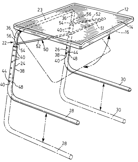
A folding table has a table top of synthetic plastic material with an upper working surface and an underside, the underside having at least one rearwardly located leg retainer and at least one forwardly located strut retainer. A leg assembly has an elongated connecting member and a pair of legs extending from opposite ends of the connecting member, each leg having a foot member extending from a lower end thereof remote from the connecting member. An angularly movable strut is pivotally secured at the rear to at least one of the legs and is releasably engageable at the front with the strut retainer. The strut is angularly moveablebetween a working position in releasable engagement with the strut retainer to maintain the tabletop in a working position and a retracted position between thelegs when released from the strut retainer. The or each leg retainer retains theconnecting member in engagement therewith while permitting angular movement of the table top between a working position and a folded position in which the table top is substantially parallel to the legs.


French Abstract

Une table pliante possède un dessus de table en matière plastique synthétique avec une surface de travail supérieure et une sous-face dotée d'un élément postérieur de retenue de jambe et aussi au moins un élément antérieur de retenue de mât. Une jambe de soutien comprend un élément de connexion allongé et une paire de jambes s'étendant à partir des extrémités opposées de l'élément de connexion, chaque jambe possède un élément de pied qui s'étend à partir d'une extrémité inférieure éloignée de l'élément de connexion. Un mât amovible de façon angulaire est fixé de façon à pouvoir tourner au niveau de sa partie arrière jusqu'à l'un des jambes au moins et peut être connecté (de façon libérable) au niveau de sa partie avant, avec l'élément de retenue de mât. Le mât peut se déplacer de manière angulaire entre une position fonctionnelle dans laquelle il est connecté (de façon libérable) avec l'élément de retenue afin de maintenir le dessus de table sur une position fonctionnelle, et une position rétractée entre les jambes lorsqu'elle est libérée de l'élément de retenue. L'élément de retenue ou chaque élément de retenue de jambe retient l'élément de connexion en place tout en permettant le déplacement angulaire du dessus de table entre une position fonctionnelle et une position rétractée dans laquelle le dessus de table est sensiblement parallèle aux jambes.

Claims

Note: Claims are shown in the official language in which they were submitted.


I CLAIM:
1. A folding table comprising:
a table top of synthetic plastic material having an upper
working surface and an underside,
said underside having a laterally spaced pair of rearwardly
located leg retainers and a laterally spaced pair of forwardly located
strut retainers, said leg and strut retainers being formed as part of
said table top and being integral therewith,
a leg assembly comprising an elongated connecting member
and a pair of legs extending from opposite ends of the connecting
member, each leg having a foot member extending from a lower end
thereof remote from the connecting member, and an angularly
movable strut pivotally secured at a rear end thereof to at least one
of the legs and releasably engageable at a front end thereof with the
strut retainers,
each integral leg retainer comprising a closely laterally spaced
pair of substantially identical integral leg retainer members each
retaining the connecting members in snapping engagement therewith,
and each integral strut retainer comprising a closely laterally spaced
pair of substantially identical integral strut retainer members each
retaining the strut in releasable engagement therewith,
said strut being angularly moveable between a working
position in releasable engagement with the strut retainers to maintain


the tabletop in a working position and a retracted position between
the legs when released from the strut retainers,
each leg retainer retaining the connecting member in
releasable snapping engagement therewith while permitting angular
movement of the table top between a working position and a folded
position in which the table top is substantially parallel to the legs.


2. A folding table according to claim 1 wherein each strut retainer
receives the strut in releasable snapping engagement therewith.


3. A folding table according to claim 1 wherein each strut retainer can
receive the strut in releasable engagement therewith at a plurality of
positions spaced from one another in a front to rear direction.


4. A folding table according to claim 1 wherein the strut comprises a
pair of laterally-spaced side members each pivotally secured at a rear
end to a respective leg and a transverse member extending between
the front ends of the side members, said transverse member being
received by each strut retainer in releasable engagement therewith in
the working position.


5. A folding table according to claim 1 wherein said legs each have
upper and lower portions in telescoping engagement, the lower leg


portions being securable at different longitudinal positions relative to
the upper portions to vary the length of the legs.


6. A folding table according to claim 5 wherein the lower leg portions
are angularly movable relative to the upper leg portions about the
longitudinal axes of the legs, the lower leg portions being securable
in working positions in which the foot members are parallel to one
another and folded positions in which the foot members extend in
opposite directions side-by-side one another.


Description

Note: Descriptions are shown in the official language in which they were submitted.


- 2110875
FOLDING TABLE
This invention relates to folding tables.
There are of course many known different kinds of folding tables.
However, there is still a need for a versatile folding table which is of simple yet
attractive construction and which can be easily erected and folded.
According to the invention, a folding table comprises a table top of
synthetic plastic material having an upper working surface and an underside, theunderside having at least one rearwardly located leg retainer and at least one
forwardly located strut retainer, a leg assembly comprising an elongated connecting
member and a pair of legs extending from opposite ends of the connecting member,each leg having a foot member extending from a lower end thereof remote from theconnecting member and an angularly moveable strut pivotally secured at the rear
to at least one of the legs and releasably engageable at the front with the strut
retainer. The strut is angularly moveable between a working position in releasable
engagement with the strut retainer to maintain the table top in a working position
and a retracted position between the legs when released from the strut retainer.The or each leg retainer retains the connecting member in engagement therewith
while permitting angular movement of the table top between a working position
and a folded position in which the table top is substantially parallel to the legs.
The underside of the table top may have a laterally-spaced pair of
rearwardly located leg retainers, and the or each leg retainer may retain the
connecting member in releasable snapping engagement therewith. The or each leg
retainer may comprise a closely spaced pair of substantially identical leg retainer
members which each retain the connecting member in engagement therewith.
The underside of the table top may have a laterally-spaced pair of forwardly
located strut retainers, and the or each strut retainer may receive the strut in

2110875
releasable snapping engagement therewith. The or each strut retainer may receivethe strut in releasable engagement therewith at a plurality of positions spaced from
one another in a front to rear direction. The or each strut retainer may comprise
a closely-spaced pair of substantially identical strut retainer members which each
receive the strut in releasable engagement therewith.
The strut may comprise a pair of laterally-spaced side members each
pivotally secured at a rear end to a respective leg and a transverse member extending
between the front ends of the side members, the transverse member being receivedby the or each strut retainer in releasable engagement therewith in the working
position. The legs may each have upper and lower portions in telescoping
engagement, the lower leg portions being securable at different longitudinal
positions relative to the upper portions to vary the length of the legs.
The lower leg portions may be angularly movable relative to the upper leg
portions about the longitudinal axes of the legs, the lower leg portions being
securable in working positions in which the foot members are parallel to one
another and folded positions in which the foot members extend in opposite
directions side-by-side one another.
One embodiment of the invention will now be described, by way of
example, with reference to the accompanying drawings, of which
Fig. 1 is a perspective view of a folding table in accordance with one
embodiment of the invention, the table top being in a horizontal working position,
Fig. 2 is a detailed view of the portion of a table leg indicated by the arrow
2 in Fig. 1,
Fig. 3 is a perspective view of the table with the table top in an inclined
working position and showing the underside of the table top,

211087~
Fig. 4 is a perspective view of the table in the fully folded condition,
Fig. 5 is a sectional detail view along the line 5-5 of Fig. 3 of a rear portionof a table top showing a leg retainer and part of the leg assembly, and Fig. 6 is a
similar view along the line 6-6 of Fig. 3 of a front portion of the table top showing
a strut retainer and part of the strut.
Referring to the drawings, a folding table 10 has an integrally molded plastic
table top 12 in the form of a rectangular panel with rounded corners, the table top
12 having an upper working surface 14 and an underside 16. The underside 16 has
a laterally-spaced pair of rearwardly located integral leg retainers 18 and a laterally-
spaced pair of forwardly located integral strut retainers 20. A leg assembly 22 of
tubular steel comprises a transverse connecting member 23 and a pair of legs 24, 26
extending from opposite ends of the connecting member 23, each leg 24, 26 havingan elongated foot member 28, 30 respectively extending from the lower end thereof.
Each leg retainer 18 comprises a closely-spaced pair of identical leg retainer
members 32 which each have hook portions 34 to retain the connecting member
23 in releasable snapping engagement therewith and permit the table top 12 to bemoved angularly relative to the leg assembly 22 in a manner which will be described
in more detail later.
Each leg 24, 26 has upper and lower portions 36, 38 in telescopic
engagement, the lower leg portions 38 being slidable over the upper leg portions 36.
Each upper leg portion 36 is integral with the relevant end of the connecting
member 23, and each lower leg portion 38 is integral with the respective foot
member 28, 30, the foot members 28, 30 thus also being of tubular steel. Each
lower leg portion 38 has a series of vertically-spaced apertures 40 on its laterally
outer and inner sides, and each upper leg portion 36 contains a resilient U-shaped

211087~
catch member 42 adjacent its lower end as shown in Fig. 2. The catch member 42
has a pair of projections 44 which project through apertures 46 in the upper legportion 38 on opposite sides thereof. The projections 44 are snappingly engageable
in selected pairs of apertures 40 in the lower leg portions 38 to enable the length of
the legs 24,26 to be adjusted as indicated in dotted outline in Fig. 1.
For folding purposes, as will be described in more detail later, the lower leg
portions 38 can be rotated about their longitudinal axis to the laterally-inwardly
extending positions shown in dotted outline in Fig. 3. Each lower leg portion 38also has an aperture 48 on a front surface so that one of the projections 44 can snap
thereinto to retain the lower leg portions 38 in the inwardly folded position.
An angularly movable strut 50 is pivotally secured at the rear to the upper
leg portions 36. The strut 50 is a metal rod bent to provide a transverse member51 at the front and a pair of laterally-spaced side members 52 extending rearwardly
from opposite ends thereof. Each side member 52 has a bent free end portion 54
at the rear extending into an aperture 56 in the respective upper leg portion 36 to
pivotally secure the strut 50 thereto. Each strut retainer 20 comprises a closely-
spaced pair of identical strut retainer members 58 which each have a series of hook
portions 60 spaced from one another in the front to rear direction which can each
retain the transverse strut member 51 in releasable snapping engagement therewith.
Fig. 1 shows the table in the fully erected position with the table top 12
horizontal. It will be understood that to retain the table top 12 in the horizontal
position, the transverse strut member 51 is snapped in to the strut retainer hook
portion 60 furthest from the front of the table top 12. The foot members 28,30
extend forwardly from the legs 24,26 beneath the table top 12. If it is desired to
position the table top 12 in an inclined manner as indicated in dotted outline in Fig.

2110875
1 and shown in more detail in Fig. 3, the transverse strut member 51 is snapped
into strut hook portions 60 nearer the front of the table top 12.
The table can be completely folded as shown in Fig. 4, by swinging the foot
members 28, 30 inwardly as previously described and releasing the transverse strut
retainer 51 from the retainer hook portions 60 and permitting the strut 50 to pivot
downwardly to a near vertical position. The table top 12 can then be permitted to
swing downwardly in the same manner.
The foot members 28, 30 can be left in the forwardly extending position
shown in Figs. 1 and 3, and the strut 50 and table top 12 put in the near vertical
position so that the members 28, 30 can be slid under the side or rear of a chair or
couch with the table top 12 adjacent the side or rear of the chair or couch. Thetable is thus then readily accessible for future use, it merely being necessary to slide
the table out and position the table top 12 by means of the strut 50.
It will be clear from the above description of a preferred embodiment that
the present invention provides a folding table which is of simple yet attractiveconstruction and which can be easily erected and folded.
Other embodiments of the invention will be readily apparent to a person
skilled in the art, the scope of the invention being defined in the appended claims.

Representative Drawing
A single figure which represents the drawing illustrating the invention.
Administrative Status

For a clearer understanding of the status of the application/patent presented on this page, the site Disclaimer , as well as the definitions for Patent , Administrative Status , Maintenance Fee  and Payment History  should be consulted.

Administrative Status

Title Date
Forecasted Issue Date 1996-01-09
(22) Filed 1993-12-07
(41) Open to Public Inspection 1995-04-16
Examination Requested 1995-07-27
(45) Issued 1996-01-09
Expired 2013-12-09

Abandonment History

There is no abandonment history.

Payment History

Fee Type Anniversary Year Due Date Amount Paid Paid Date
Application Fee $0.00 1993-12-07
Maintenance Fee - Application - New Act 2 1995-12-07 $50.00 1995-09-05
Registration of a document - section 124 $0.00 1995-11-02
Maintenance Fee - Patent - New Act 3 1996-12-09 $50.00 1996-10-10
Maintenance Fee - Patent - New Act 4 1997-12-08 $50.00 1997-10-17
Maintenance Fee - Patent - New Act 5 1998-12-07 $75.00 1998-10-28
Maintenance Fee - Patent - New Act 6 1999-12-07 $150.00 1999-11-10
Maintenance Fee - Patent - New Act 7 2000-12-07 $150.00 2000-11-20
Maintenance Fee - Patent - New Act 8 2001-12-07 $150.00 2001-10-18
Maintenance Fee - Patent - New Act 9 2002-12-09 $150.00 2002-09-24
Maintenance Fee - Patent - New Act 10 2003-12-08 $200.00 2003-11-13
Maintenance Fee - Patent - New Act 11 2004-12-07 $250.00 2004-11-08
Maintenance Fee - Patent - New Act 12 2005-12-07 $250.00 2005-10-07
Maintenance Fee - Patent - New Act 13 2006-12-07 $250.00 2006-11-03
Maintenance Fee - Patent - New Act 14 2007-12-07 $250.00 2007-10-18
Maintenance Fee - Patent - New Act 15 2008-12-08 $450.00 2008-10-02
Maintenance Fee - Patent - New Act 16 2009-12-07 $450.00 2009-10-16
Maintenance Fee - Patent - New Act 17 2010-12-07 $450.00 2010-09-17
Maintenance Fee - Patent - New Act 18 2011-12-07 $450.00 2011-10-07
Maintenance Fee - Patent - New Act 19 2012-12-07 $450.00 2012-12-05
Owners on Record

Note: Records showing the ownership history in alphabetical order.

Current Owners on Record
INO-PRODUCTS INC.
Past Owners on Record
SOPER, DOUGLAS
Past Owners that do not appear in the "Owners on Record" listing will appear in other documentation within the application.
Documents

To view selected files, please enter reCAPTCHA code :


To view images, click a link in the Document Description column. To download the documents, select one or more checkboxes in the first column and then click the "Download Selected in PDF format (Zip Archive)" or the "Download Selected as Single PDF" button.

List of published and non-published patent-specific documents on the CPD .

If you have any difficulty accessing content, you can call the Client Service Centre at 1-866-997-1936 or send them an e-mail at CIPO Client Service Centre.


Document
Description 
Date
(yyyy-mm-dd) 
Number of pages   Size of Image (KB) 
Cover Page 1995-06-05 1 40
Abstract 1995-06-05 1 39
Claims 1995-06-05 3 150
Drawings 1995-06-05 3 136
Description 1995-06-05 5 273
Cover Page 1996-01-09 1 15
Abstract 1996-01-09 1 27
Description 1996-01-09 5 204
Claims 1996-01-09 3 79
Drawings 1996-01-09 3 104
Representative Drawing 1998-05-14 1 26
Fees 2003-11-13 1 30
Fees 2001-10-18 1 30
Fees 2007-10-18 1 31
Fees 1998-10-28 1 45
Fees 2000-11-20 1 32
Fees 2002-09-24 1 29
Fees 1997-10-17 1 41
Fees 1999-11-10 1 40
Fees 2004-11-08 1 29
Fees 2005-10-07 1 34
Prosecution Correspondence 1995-07-27 2 68
Prosecution Correspondence 1995-07-27 1 31
Office Letter 1995-08-18 1 24
PCT Correspondence 1995-10-03 1 34
Fees 2006-11-03 1 31
Fees 2008-10-02 1 30
Fees 2009-10-16 1 33
Fees 1996-10-10 1 46
Fees 1995-09-05 1 30