Note: Descriptions are shown in the official language in which they were submitted.
(3 ~1 ~
STENT
Backqround of the Invention
This invention generally relates to assemblies for
delivering devices to a situs in a body passageway and in
particular, to assemblies comprising an outer sheath
containing an elongated catheter therein for delivering
the distal portion of the catheter to a situs in a body
passageway such as a blood vessel or bile duct. The
assembly is adapted to be percutaneously inserted into a
body passageway, sometimes by means of a guide catheter.
For example, the assembly is introduced percutaneously
into the femoral artery and then advanced, distally,
through the arterial system to a desired situs, e.g. at
the situs of an atherosclerotic lesion. Once located, the
proximal end of the sheath may be manipulated so as to
expose the distal portion of the catheter to the situs,
whereafter the intended medical procedure may progress.
For example, the so- located distal end of the catheter
may include an inflatable balloon for carrying out a
percutaneous translumenal coronary angioplasty procedure.
Alternatively, a prosthesis such as a stent, graft, or
stent/graft combination may be delivered, by the catheter
to such situs. The situs need not be in a blood vessel
but instead may be some other body passageway such as the
urethra or a bile duct. Currently, procedures are
performed for stenting such body passageways.
Descriptions of such procedures and the devices and
apparatus associated therewith are exemplified by
reference to the following U.S. Patents: U.S. Patent Nos.
4,299,226 issued November 10, 1981 to Banka; 4,323,071
issued April 6, 1982 to Simpson, et al.; 4,581,017 issued
JJI- l0
2i~ A~
April 8, 1986 to Sahota; 4,748,9~2 issued January 7, 1988
to Horzewski, et al.; 4,773,899 issued September 27, 1988
to Spears; 4,848,344 issued July 18, 1989 to Sos, et al.;
4,885,003 issued December 5, 1989 to Hillstead; 4,932,959
issued June 12, 1990 to Horzewski~ et al.; 4,998,917
issued March 1~, 1991 to Gaiser, e~ al.; 4,998,923 issued
March 12, 1991 to Samson, et al.; 5,0U7,898 issued April
16, 1991 to Rosenbluth, et al.; 5,034,001 issued July 23,
1991 to Garrison, et al.; and 5,116,309 issued Mary 26,
1992 to Coll.
In carrying out the proceduresi described and
exemplified above using heretofore available apparatus,
several difficulties have been encountered and, while in
lS some instances, the art has attempted to cure these
difficulties, the state of the art is such that
improvement is highly desired.
Specifically, one difficulty heretofore encountered
is the problem of threading the elongated catheter through
a tortuous passageway system. In doing so, one is faced
with the requirement that the assembly have the requisite
stiffness (often termed "pushability" in the art) to
transmit the pushing forces exerted on the proximal end of
the assembly and move the assembly in a distal direction
through the passageway without the assembly bending,
kinking, crimping or collapsing. At the same time, the
assembly must be led through the tortuous passageway,
conforming to all the bends and turns that are therein
encountered. This need for both stiffness and
conformability is in conflict and such conflict heretofore
is manifested in disappointing and unsatisfactory
performance of prior art devices~
JJI-
. , . .:
;~ . , " !:; ,' 'i, : , ' , .
',:,''".' " ' ' `' ' ' ` ' ' ' ~ ' `: ,. . .
.i~' . ':: ,:, , , ,,: ,, ,....... : : ',. ,., ' :
4 3
Still another difficulty has been encountered in the
employment of the subject devices. In pushing the
assemblies through the body passageways, there is the
great danger of abrading or otherwise traumatically
affecting the inner walls of these passageways. The
vascular system is particularly vulnerable to such
undesirable abrasion. Still further, generally in
connection with an emplaced sheath/conkained catheter
assembly, there is always the danger that the sheath will
move relative to the catheter in an undesired direction,
such undesired direction being generally the distal
direction. Such movement, for example, during a procedure
would obviously be disruptive. Accordingly, thexe is a
nee~d to obviate such undesired movement.
Summary of the Invention
In accordance with the teachings herein improved
catheters and sheaths are provided which can cooperate to
form an assembly obviating the above-described
shortcomings of prior devices.
In one aspact of this invention a sheath is provided
for containing a device to be delivered to a situs in a
body passageway e.g., for delivering to such situs the
distal portion of a catheter. The sheath comprises an
elongated polymeric tube having an open proximal end and
an open distal end and a lumen for containing the device,
such as a catheter, therein. In accordance with this
invention the out~lde diameter of the sheath at its distal
portion is smaller than the outside diameter of such
sheath at its proximal portion. Preferably, the smaller
diameter distal portion is at only the portion closely
adjacent to the distal end and extends for only a small
I
I JJI-
2 ~
fraction of the length of the sheath at the distal end.
Further, the hardness of the polymeric material employ~d
~ for such smaller diameter portion is less than the
hardness of the polymeric material employed for the
remainder of the sheath. Finally, the wall thickness of
- the smaller diameter portion is less than that of the
remainder of the sheath. The combination of smaller
diameter, lesser hardness and smaller wall thickness
results in a flexible, conformable leading distal portion
of the assembly as it is being pushed distally through the
tortuous body passageway. On the other hand, the major
and lagging proximal portion of the sheath by virtue of
its larger diameter, harder polymeric material of
construction and larger wall thickness, is designed to
have the requisite "pushability" to transmit forces and
translate the assembly distally through the body
passageway. As described herein, all of the above may be
accomplished by economically practical manufacturing
methods and hence, provides a simple yet highly effective
solution to a longstanding problem in this field.
While the differential pushability/conformability of
the sheath has been described by a device wherein the
diameter, wall thickness and hardness of the respective
portions have all been varied, it ~ill be understood that
a selection of one or more of these parameters may, in
certain instances, produce the desired differential
pushability/conformability.
In another aspect of this invention, an elongated
catheter is provided having a proximal end and a distal
end. The catheter is adapted to be contained in an
elongated tubular sheath Eor the purpose of having the
distal end of such catheter delivered to a situs in a body
JJI-
.
2~.'L2(')~5
passageway. The catheter comprises an elongated member
having at least one lumen therethrough, the member having
an outer longitudinally extending surface.
In accordance with the teachings herein, the outer
surface is provided with a toroidal enlargement in close
proximity to the distal end of the ca~heter. This
toroidal enlargement presents, in the longitudinal cros
sectional view of the catheter, a smooth curve. In
assembled form, the catheter is contained within the
sheath and the inner lumen of the sheath may now be sized
such that the dis~al end of the sheath, in its extreme
distal position with respect to the catheter, bears
against the proximal portion of the toroidal enlargement
and hence is precluded from further distal relocation with
respect to the catheter. Accordingly, the highly
undesirable relocation of the sheath during a medical
procedure is obviated.
The combination of the new sheath as described above
together with the catheter taught herein is particularly
advantageous in that the reduced diameter of the distal
portion of the sheath allows such portion to be impeded
distally by the enlargement without increasing the largest
profile of the sheath. That is to say, the enlargement
may be sized to correspond to the profile of the proximal
end of the sheath with the smaller distal end still
bearing against the enlargement.
~0 In another aspect of this invention, in the specific
case of a catheter carrying a prosthesis such as a stent,
the same toroidal enlargement placed distally to the stent
will prevent the distal displacement of the stent relative
to the catheter.
JJI-
,: . , : . , ": :
., . :.: : . : : . ,
2 ~ .3
These and other unique features and benefits of this
invention shall be apparent from the following detailed
descriptions and drawings.
Brief Description of the Drawinas
The invention will be better understood from the
following detailed description of exemplary embodiments
thereof taken together with the drawing in which:
Figure 1, consisting of Figs. lA, lB and lC, is an
elevational, discontinuous view of an assembled sheath and
catheter embodying this invention and shown in partial
longitudinal cross section wherein
Figure lA is the proximal portion of the assembly
including a proximal fitting and a guide wire;
Figure lB is an intermediate portion of the assembly
including an intermediate fitting;
Figure lC is the distal portion of the assembly, in
partial cross section to reveal an inflatable balloon
carrying a stent thereupon;
Figure 2 is an enlarged longitudinal cross sectional
view of the balloon catheter embodying the teachings of
this invention shown in Figure lC, with the sheath removed
and the balloon expanded;
Figure 3 is an enlarged, transverse cross sectional
view of the portion of the catheter illustrated in Fig. 2
and taken through line 3-3;
Figure ~ illustrates in longitudinal, elevation view
a stent: useflll in connection with the assembly illustrated
in the above drawings; and
JJI-
2 (~
Figure 5 is an enlargement of a portion of the stent
shown in Figure 4.
Detailed Description of the Invention
Referring now to the drawings, illustrated in Figure
1 (Figs. lA thru lC) is a sheath/catheter assembly 10
embodying the teachings of this invention. The sheath 12
is designed to deliver the distal portion 14 of a device,
which in the illustrated embodiment is the balloon
catheter 16, to a situs in a body passageway which, for
the purpose of this specific exemplification, i5 a blood
vessel such as a coronary artery. It will, of course, be
appreciated that other body passageways such as bile ducts
or urethras are also contemplated. The sheath 12
comprises an elongated polymeric tube having an open
proximal end 18 (hidden in Fig. lB) and an open distal end
20, and contains the catheter 16 therein. The sheath is
divided into a relatively long "pushable" proximal portion
22 and a relatively short conformable distal portion 24.
The length of the distal portion 24, in accordance with
this invention, is selected to be long enough to conform
to the bends and twists of the body passageway through
which the assembly must be threaded and lead the remainder
of the assembly therethrough. For example, typically a
catheter for carrying a stent to a body passageway and
passage to the desired situs may range in lengths o~ from
about 35 cm. to about 175 cm. and more typically from
about 50 cm. to about 160 cm. The shorter catheters for
use in peripheral stenting (e.g., in a femoral or iliac
30 artery) may vary from about 35 crto about 90 cm. and the
longer catheters for coronary stenting may range from
about 90 cm. to about 175 cm. e.g., about 150 cm. The
sheath, of course, will be about the same length.
JJI-
`.' "' ' ' , ' .,. : '. ~ . ' ~ ' ' '''
2 ~ 3
In accordance with the teachings of this invention,
it is preferred that the sheath be so divided in distal
~ and proximal portions so tha~ the distal portion is a
length of from about 1 cm. to about 35 cm. and more
preferably from about 1 cm. to about 12 cm. For example,
- the distal portion may be 12 cm.
As exemplified, the distal portion 24 of the sheath
12 is more conformable then the relatively stiff proximal
portion 22 by virtue of having a relatively smaller
diameter, a thinner wall thickness and being constructed
of a polymer having a lower hardness value.
The diameter of the distal portion 24 is limited by
the highest profile of the contained device in that it is
important that such diameter be large enough to allow the
distal portion 24 to be easily manipulated to slide over
the corresponding distal portion of the device. Beyond
this limitation, the diameter should be as small as
possible within the practical manufacturing limits so as
to present the least trauma and the most conformability to
this leading end of the sheath 12. It will be recognized
by those skilled in the art that some stiffness will be
required but for all practical purposes, a distal portion
having the requisite diameter to aLlow the distal portion
of the catheter to slide therein, will have the necessary
minimal stiffness to lead the remainder of the sheath
through the pathway to the desired situs. In contrast
with the distal portion 26, the proximal portion 22 is
limited in diameter only by the desire to minimize any
trauma to the walls of the body passageways through which
it must pass, except of course, it must retain sufficient
flexibility to be lead through the pathway by the
conformable distal portion. Generally, the constraint
JJI-
with respect to body passageway trauma will control and
preclude selecting a diameter for the proximal portion
which would be tbO stiff to manipulate through the
pathway. Typically, the distal porkion of the sheath may
vary from an outside diameter of from about 0.6 mm. (2
French) to about 6 mm. (18 French) and more preferably,
from about 0.6 mm. (2 French) to about 2O3 mm. (7 French).
The outside diameter of the proximal portion should vary
from about 1 mm. (3 French) to about 6.3 mm. (19 French)
and more preferably, from about 1 mm. (3 French) to about
2.7 mm. (8 French). For example, the diameter of the
distal portion may be 1.55 mm. (4.5 French) and the
diameter of the proximal portion may be 1.7 mm. (5
French).
A second contributing factor to the differential
pushability/conformability of the distal portion, as
compared to the proximal portion, is wall thickness; the
distal portion having a wall thickness less than that of
the proximal portion. Such wall thickness for the distal
portion may vary from about 0.0005 inches to about 0.05
inches and preferably from about 0.001 inches to about
0.006 inches, for example, 0.003 inches. In contrast
thereto, the wall thickness of the proximal portion varies
from about 0.0006 inches to about 0.06 inches and more
preferably, from about 0.004 inches to about 0.006 inches,
for example, 0.005 inches.
Still a third factor selected for providing the
differential pushability/conformability between the sheath
portions is the hardness of the polymer employed; a hard
polymer for the pushable proximal portion and a soft
polymer for the conformable distal portion. Such polymers
as are used currently, generally can be purchased in
JJI-
-
,... 1 ~. 2 5 ) ~ ~
-- 10 --
varying compositions which can result in extruded tubes
with varying stiffness. Typically, polymersi employed for
this purpose are, for example, polyethylenes,
polyurethanes, and in some cases, nylons. The polymer of
choice is a polyether block polyamide composition sold by
the Atochem Corporation of Pennsylvania, under the trade
name "PEBAX". Such PEBAX polymer comes in varyiny
hardnesses, ranging from about 25 to about 70 Shore D
Durometer values, as the extruded polymer is tested in
accordance with the ASTM 1147 standard test procedure for
Shore D Durometer values. The proximal portion is
preferably about 50 to about 70 in Shore D Durometer and
more preferably, about 60 to about 70. In contrast
thereto, the distal portion is preferably about 25 to
about 60 and more preferably, about 40 to about 60 in
Shore D Durometer value.
As best seen in Fig. lC, the two portions are joined
together by force fitting the larger diameter portion into
the smaller and then "welding" by the application o~
energy e.g., heat, whereby the polymers fuse to seal the
parts together. In an alternative method of construction
the two portions could be continuously co-extruded with
polymer of one hardness being first fed to the extruder
unit at an upstream station and a polymer of the other
hardness being fed in downstream thereof.
Again referring to the drawings, in operation, a
guide wire 26 is generally first introduced into the body
passageway and then the sheath/catheter assembly 10 is
threade!d over the guide wire 26 by threading such guide
wire through a provided guide wire lumen 28, best viewed
in Fig. 2. The annular space between the sheath 12 and
the catheter is generally flushed with fluid, such as
JJI-
saline solution, to free the annulus of air which
otherwise may be carried into the body passageway. This
is accomplished via sheath flush port 39 which is in
intermediate fitting 32 and in flow communicakion with the
sheath annulus. The assembly is then advanced through the
body passageway until the distal portion of the catheter
is in the desired position. Referring to Fig. 2, which
illustrates this distal portion o~ the catheter, radio
opaque markers 30 are provided whereby the progress and
positioning of the catheter may be monitored by the doctor
using x-ray. Once positioned, the distal portion 22 of
the sheath may be drawn back proximally to expose the
distal portion of the catheter to the situs. This is
accomplished by moving the intermediate fitting 32
proximally relative to the proximal fitting 34. The
sheath 12 is affixed to this intermediate fitting 32 at
its proximal end and the catheter is affixed to the
proximal fitting 34 via a stiffening section 36.
Accordingly, the translation of the intermediate fitting
32 proximally toward the proximal fitting 34 will result
in a proximal withdrawal of the distal portion of the
she.ath from the catheter. This operation is aided by
employing the stiffening section 36 in that the catheter
itself is generally flexible and manipulation of the
catheter is greatly facilitated by such stiffening means.
The sheath may be locked into its position by locking
means 38 carried on the intermediate fitting. Such
locking means 38 may, for example, comprise a so-called
"hemostasis valve e.g., a Tuohy Borst valve"~
The catheter itself comprises an elongated tube 41
having an outer surface. As exemplified in the drawings
and best seen in Fig. 2 and 3, the elongated tube contains
a guide wire lumen 2~ and a balloon inflation lumen 40 for
JJI-
2 ~ ii3
- 12 ~
carrying fluid to inflate balloon 42. Balloon 42 is
circumferentially affixed to the distal end of the
~ elongated tube by such means as welding or gluing. The
balloon is made of such a material ana is sized such
that, in its area of expansion, it is capable of
- presenting an increased diameter when inflated by pressure
exerted by the introduction of inflating fluid directed to
the balloon via inflation lumen 40 through inflation lumen
port 43. When pressure from such inflation fluid in
withdrawn, the balloon collapses to a lesser diameter
allowing for the retraction of the catheter. Inflation
fluid can be introduced into inflation lumen 40 via
inflation fluid port 44 which is contained within proximal
fitting 34 and is in flow communication with inflation
lumen 40 (see Fig. lA).
In the embodiment shown in Fig. 2, the wire lumen 28
of the elongated tube 41 terminates at the proximal
portion of the balloon. It is necessary for the guide
wire 26 to be threaded through the entire catheter and
extend from the distal end thereof as is illustrated in
Fig. lC. It is also necessary that the entire lumen
carrying the guide wire be sealed so as not be in flow
communication with the inflating fluid. These goals are
accomplished by inserting into the-distal portion of the
guide wire lumen 28, a lumen extension ~6 which is a lumen
containing tube for containing the guide wire in the
portion of the catheter extending from the distal portion
of the guide wire lumen 28 and through the distal end of
the catheter 48. To insure fluid tight sealing, the
extension 46 is sealed about the inside surface of the
distal portion of the guide wire lumen 28 by adhesive or
heat sealing means, for example. At the distal end of the
balloon, sealing is provided by extending the balloon into
JJI-
; v ~
'7, .~ ~ 2 ~
- 13 -
a circumferential flange 50 and sealing this flange 50 to
the lumen extension 46. The extension 46 also, usefully,
carries the radio-opaque markers 30 which may, for
example, be gold bands.
As described herein, heretofore there has been a
danger of the undesired movement of the distal end of the
sheath with respect to an emplaced catheter Accordinyly,
the outer surface of the catheter at the flange 50 of the
balloon has been provided with a toroidal enlargement 52
which pr~sents, in the longitudinal cross sectional view
shown in Fig. 2, a smooth curved surface. The enlargement
is sized relative to the sheath such that when the
catheter is contained within the sheath, the distal end 20
of the sheath, in its extreme distal position as shown in
Fig. lC, bears against the enlargement 52 and precludes
further distal relocation with respect to the catheter.
The curved surface of th.is enlargement, in addition to
precluding such undesired movement of the sheath, has the
added benefit of providing a smooth non abrading point of
contact with the body passageway as the assembly is being
inserted and positioned therein, as contrasted with the
blunt end of the sheath, for example. In contrast with
the relatively flexible inflatable portion of the balloon
which must inflate and collapse, the toroidal enlargement
is relatively rigid and remains at all times in its
enlarged configuration. This may be accomplished by
manufacturing the balloon integrally with the flange 50
carrying the enlargement by a molding process and varying
the flexibility of the inflatable section from that of the
flange by varying the wall thickness of these sections.
As illustrated in the drawings, the wall thickness of the
inflatable section of the balloon is shown to be thinner
than that of the flange portion. ~aterials useful for
JJI-
2, ~ .~
this purpose are such pol~mers as ethylene-methacrylic
acid polymer, polyurethane, polyethyleneterephthalate,
with polyethylene being the material o~ choic~i.
Alternatively, the enlargement may be made o~ a similar or
dissimilar material and attached to the flange by means
such as gluing, welding or the like.
As has been described herein and as is illustrated in
Fig. lC, the balloon may carry an expandable stent 54 for
emplacement within a body passageway. Such stents and
their delivery and function are well described in U.5.
Patent No. 4,733,665 issued March 29, 1988 to Julio C.
Palmaz; U.S. Patent No. 4,739,762 issued April 26, 1988 to
Julio C. Palmaz; and U.S. Patent No. 5,102,417 issued
April 7, 1992 to Julio C. Palmaz and Richard Schatz which
are all incorporated by reference herein. The toroidal
enlargement 52, in connection with the placement of such
stents is further useful in precluding the undesirable
movement of the stent distally into the body passageway
before it is expanded.
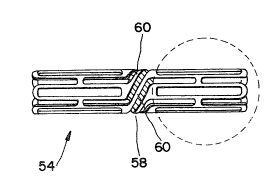
As illustrated in Fig~ 4, a stent 54 is provided
comprisinq a metal tube, open at both ends and having a
series of slots 56 therein which allow such stent to be
radially expanded into an enlarged diameter by the
de~amation of the metal under the action of an expanding
force such as the expanding balloon of a balloon catheter.
The stent 54 is provided in an intermediate position along
its longitudinal length with an articulatable section 58.
This section links the portion of the stent with bendable
metal struts 60 which can be bent and provide the stent
with a degree of conformability along its length. The
stent and its slots are also provided with rounded ends
62, which in contrast to blunt ends, provide a smooth
JJI-
2 ~ C3
- 15 -
surface with no danger of abrading the walls of the body
passageway or piercing the balloon of the catheter. Owing
to the extremely small size of the stents (as small as
less than about 0.5 mm. (less than 2 French~ in diameter)
the shaping of these ends, as well as the shaping of the
struts in the articulatable section, is very difficult to
accomplish with conventional equipment. Such shaping may
be accomplished by the use of etching techniques but it
has been found that the preferred method is to employ
laser cutting apparatus.
While the invention has been described herein in
connection with certain preferred embodiments, it will be
apparent to those skilled in the art that various
modifications and improvements can be made thereto without
departing from the scope thereof.
JJI-
~$
i: :::: . i , , . ~, ,