Language selection

Search

Patent 2120015 Summary

Third-party information liability

Some of the information on this Web page has been provided by external sources. The Government of Canada is not responsible for the accuracy, reliability or currency of the information supplied by external sources. Users wishing to rely upon this information should consult directly with the source of the information. Content provided by external sources is not subject to official languages, privacy and accessibility requirements.

Claims and Abstract availability

Any discrepancies in the text and image of the Claims and Abstract are due to differing posting times. Text of the Claims and Abstract are posted:

  • At the time the application is open to public inspection;
  • At the time of issue of the patent (grant).
(12) Patent Application: (11) CA 2120015
(54) English Title: COATING DEVICE WITH COATING GAP FORMED BETWEEN A COATING ROLLER AND A COUNTER-ROLLER
(54) French Title: MACHINE D'ENDUCTION AVEC ESPACE AMENAGE ENTRE LE CYLINDRE D'ENDUCTION ET LE CYLINDRE ARRIERE
Status: Dead
Bibliographic Data
(51) International Patent Classification (IPC):
  • B05C 1/08 (2006.01)
  • D21H 23/56 (2006.01)
  • D21H 25/10 (2006.01)
  • B05C 11/04 (2006.01)
(72) Inventors :
  • SIEBERTH, RALF (United States of America)
(73) Owners :
  • J.M. VOITH GMBH (Germany)
(71) Applicants :
(74) Agent: SIM & MCBURNEY
(74) Associate agent:
(45) Issued:
(86) PCT Filing Date: 1993-07-26
(87) Open to Public Inspection: 1994-02-03
Availability of licence: N/A
(25) Language of filing: English

Patent Cooperation Treaty (PCT): Yes
(86) PCT Filing Number: PCT/EP1993/001981
(87) International Publication Number: WO1994/002256
(85) National Entry: 1994-03-25

(30) Application Priority Data:
Application No. Country/Territory Date
P 42 24 726.8 Germany 1992-07-27

Abstracts

English Abstract


COATING DEVICE HAVING AN APPLICATION SLOT
FORMED BETWEEN AN APPLICATOR ROLL AND A BACKUP ROLL

ABSTRACT OF THE DISCLOSURE

The present invention relates to a coating device having
an applicator roll (1) which forms; an application (10) with
the backup roll (4) which conducts the web of material (C).
The invention is characterized by the fact that, adjoining
the applicator slot (10) or the pressure space (8) which is
formed at the outlet side there between applicator roll (1)
and backup roll (4), there is arranged a preferably flexible
guide wall (2) having a shape which approximates or is
adapted to the surface of the backup roll (4) and/or can be
adapted thereto by the Coanda effect itself, which wall forms
a narrow slot (7) along the web of material and behind which
slot, at such a slight distance away that the formation of
drips or streaks in the application by the centrifugal force
is definitely excluded, the dosaging place for the final
dosaging, formed by a dosaging doctor (6), is arranged.


Claims

Note: Claims are shown in the official language in which they were submitted.


- 5 -
CLAIMS

1. A coating device having an applicator roll (1) which
forms an application slot (10) with the backup roll (4)
which conducts the web of material (C), characterized by
the fact that, adjoining the applicator slot (10) or the
pressure space, formed at the outlet side between
applicator roll (1) and backup roll (4), there is
arranged a preferably flexible guide wall (2) having a
shape which approximates or is adapted to the surface of
the backup roll (4) and/or can be adapted thereto by the
Coanda effect itself, which wall forms a narrow slot (7)
along the web of material behind which slot, at such a
slight distance away that the formation of drips or
streaks in the application by the centrifugal force is
excluded, there is arranged the dosaging place for the
final dosaging, formed by a dosaging doctor (6).

2. A device according to Claim 1, characterized by the fact
that the guide wall (2) is very flexible.

3. A device according to Claim 2, characterized by the fact
that, with a pressure difference of 0.1 bar acting on
its two sides, the guide wall has a deflection at its
free end of at least 3 mm.
4. A device according to any of Claims 1 to 3,
characterized by the fact that the slot (7) formed by


- 6 -
the guide wall is approximately constant or at most
slightly wedge-shaped, with a maximum difference in
width between its starting point and its end of at most
18%.


5. A device according to any of Claims 2 to 4,
characterized by the fact that the flexible guide wall
(2) is supported on its side facing away from the backup
roll (4) by additional fluid pressure in addition to
atmospheric pressure, at least in the start-up phase.


6. A device according to any of the Claims 1 to 5,
characterized by a strip-shaped or curtain-shaped
lubrication jet which, in the start-up phase, is
directed into or in the direction of the application
slot (10) and/or into or in the direction of the slot
(7) between flexible wall (2) and web of material (C).


Description

Note: Descriptions are shown in the official language in which they were submitted.


~ 1 2 Q ) ~ i

COATIN5 DEVICE HAVING AN APPLICATION SLOT
FORMED BETWEEN AN APPLICATOR ROLL AND A BACKUP ROLL

The present invention relates to a coating device in
accordance with the preamble to Claim 1. Such a coating
device is known from EP 403845. In this ~onnection, the
applicator roll is frequently also raferred to as scoop roll,
since the coating composition is, so to speak, scooped out of
a reservoir and fed to the backup roll in the region of the
application slot where the backup roll conducts the web of
material to be coated, which generally consists of paper or
cardboard. In this connection, only a predosing is effected
in the applicator slot so that a doctor element is generally
also provided later on on the same backup roll on the web of
material in order to effect the final dosaging. The ~ -
disadvantages of this device become particularly clear with
high speeds of the web of more than about 800 meters per
minute, so that said patent describes an improved arrangement
which does away with the applicator roll. The problems which
:: :
arise in this connection have, however, also not been -~
completely solved as yet. -~
The object of the present invention is so to develop a
:
device in accordance with the preamble to the claim that high

speeds o~ the web of 1000 meters per minute and, in

I particular, moxe than 1200 meters per minute, are possible.

¦ This object is achieved in accordance with the invention

- 2 ~ O~l~


by the features set forth in the body of Claim l.
In this connection, the rapidly moving coating
composition applied to the web is reduced or constricted to a
given thickness between the web and the flexible wall by the
difference in pressure, and the result is furthermore
obtained by the Coanda effect that this layer, despite the
centrifugal speed which is acting, remains as a uniform film
on the web, from which layer the final layer thickness can
then be scraped off also uniformly by the subsequent doctor
element.
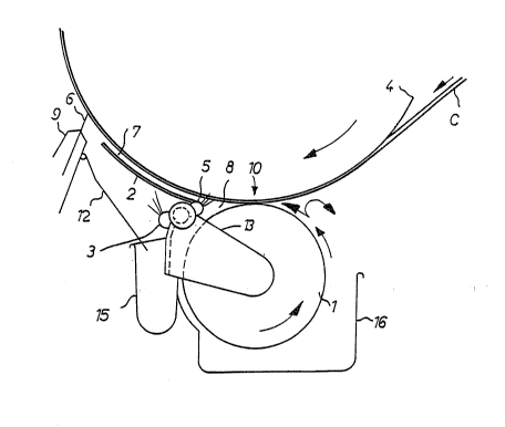
The invention will be described below with reference to
he sole figure of the drawing, which shows the device
basically in a side view.
In the figure, l is the applicator roll, 4 the backup
roll, and C the web of material. A holder 13 for the
flexible wall element 2 is mounted here in the region of the
axis of the applicator roll l. In this connection, a space 8
is formed between the flexible wall 2, the applicator roll 1,
and the backup roll 4 or web of material C, from which space
excess coating composition can be fed back to the reservoir
16 or else to another reservoir. For the starting-up
process, a spray nozzle 5 is provided which preferably sprays
a liquid, which may also be the coating composition, into the
space 8.
The coating composition therefore passes from the
reservoir 16, conveyed on the surface of the applicator roll


- 3 - 212 0 O l ~

1, to the application slot 10 over the space 8 into the slot
7 which is formed between the flexible wall 2 and the backup
roll 4 or web of material C. Here, the coating composition
is reduced to a small or smaller l:hickness of film than in
the applicator slot 10, the coating composition first -~
traveling further on the web of material and arriving at the
final dosaging element, which in this case is a doctor in the
form of a coating bl de 6. This coating blade is supported
by a mount 9 on which a deflection plate 12 is fastened in
order to conduct into a trough 15 the coating composition
which has been scraped off.
The slot 7 is at least about 50 mm long and the final
dosaging point oP the doctor 6 is arranged at most 30 mm ~-
behind the end of the slot 7 so that the coating composition
is not thrown off from the surface of the roll by the
centrifugal force. ~ `
The flexible wall 2 is very flexible, so that, as a
result of the difference in pressure between the outer side
of the wall -- mainly atmospheric pressure -- and the
pressure in the channel formed along the web of material by
the flexible wall, the wall is pressed against the web of
material and thus adjusts the size of the slot there. This
application force is possibly supported by a curtain-like
nozzle jet produced by a system of nozzles 3, which is
necessary, in particular, for the application of the flexible
wall during the start-up time. This curtain jet may consist


~ - 4 - ~2 ~ ?
:`^
o~ air or else of another fluid, for instance water.
However, air is preferred.
The flexibla wall is in this connection so thin and
flexible -- for instance of foil -- that it experiences a
deflection of at least 3 mm at its free end, with a
difference in pressure of 0.1 bar on its two sides. The
individual directions of movement of the various parts and of
the coating composition are furthermore indicated by arrows
in the figure.
By the device in accordance with the invention, a very
uniform film of coating composition is predosed onto the web
of material, the final dose being then determined, just as
uniformly, by the coating blade.
The material of which the flexible wall 2 can be made
may be very different such as, for instance, stainless steel,
possibly provided with an anticorrosion layer, steel having a
ceramic layer sprayed on the side thereof which ~aces the
web, a carbon-fiber composite foil, etc.


.- --
::,

Representative Drawing
A single figure which represents the drawing illustrating the invention.
Administrative Status

For a clearer understanding of the status of the application/patent presented on this page, the site Disclaimer , as well as the definitions for Patent , Administrative Status , Maintenance Fee  and Payment History  should be consulted.

Administrative Status

Title Date
Forecasted Issue Date Unavailable
(86) PCT Filing Date 1993-07-26
(87) PCT Publication Date 1994-02-03
(85) National Entry 1994-03-25
Dead Application 1996-01-26

Abandonment History

There is no abandonment history.

Payment History

Fee Type Anniversary Year Due Date Amount Paid Paid Date
Application Fee $0.00 1994-03-25
Registration of a document - section 124 $0.00 1994-09-09
Owners on Record

Note: Records showing the ownership history in alphabetical order.

Current Owners on Record
J.M. VOITH GMBH
Past Owners on Record
SIEBERTH, RALF
Past Owners that do not appear in the "Owners on Record" listing will appear in other documentation within the application.
Documents

To view selected files, please enter reCAPTCHA code :


To view images, click a link in the Document Description column. To download the documents, select one or more checkboxes in the first column and then click the "Download Selected in PDF format (Zip Archive)" or the "Download Selected as Single PDF" button.

List of published and non-published patent-specific documents on the CPD .

If you have any difficulty accessing content, you can call the Client Service Centre at 1-866-997-1936 or send them an e-mail at CIPO Client Service Centre.


Document
Description 
Date
(yyyy-mm-dd) 
Number of pages   Size of Image (KB) 
International Preliminary Examination Report 1994-03-25 12 416
Representative Drawing 2000-04-04 1 9
Drawings 1994-02-03 1 89
Claims 1994-02-03 2 163
Abstract 1994-02-03 1 80
Cover Page 1994-02-03 1 127
Description 1994-02-03 4 368