Language selection

Search

Patent 2120788 Summary

Third-party information liability

Some of the information on this Web page has been provided by external sources. The Government of Canada is not responsible for the accuracy, reliability or currency of the information supplied by external sources. Users wishing to rely upon this information should consult directly with the source of the information. Content provided by external sources is not subject to official languages, privacy and accessibility requirements.

Claims and Abstract availability

Any discrepancies in the text and image of the Claims and Abstract are due to differing posting times. Text of the Claims and Abstract are posted:

  • At the time the application is open to public inspection;
  • At the time of issue of the patent (grant).
(12) Patent: (11) CA 2120788
(54) English Title: DRILL STRING SHOCK ABSORBER
(54) French Title: AMORTISSEUR DE CHOC POUR TRAIN DE FORAGE
Status: Deemed expired
Bibliographic Data
(51) International Patent Classification (IPC):
  • E21B 17/07 (2006.01)
  • E21B 17/10 (2006.01)
(72) Inventors :
  • GIEN, BERNARD LIONEL (South Africa)
(73) Owners :
  • GIEN, BERNARD LIONEL (South Africa)
(71) Applicants :
(74) Agent: MACRAE & CO.
(74) Associate agent:
(45) Issued: 1999-03-30
(22) Filed Date: 1994-04-07
(41) Open to Public Inspection: 1994-10-28
Examination requested: 1995-10-10
Availability of licence: N/A
(25) Language of filing: English

Patent Cooperation Treaty (PCT): No

(30) Application Priority Data:
Application No. Country/Territory Date
93/2927 South Africa 1993-04-27

Abstracts

English Abstract


The invention concerns a shock absorber for use with a borehole drill string and which is to
take rotational load and absorb axial shock loading, the absorber consisting essentially of a
pair of oppositely disposed components adapted for connection into a drill string and
positioned on opposite sides of a resilient member the latter held between rigid rings around
and separate from the components each ring secured to the component on the opposite side
of the member.


French Abstract

Cette invention concerne un amortisseur de choc pour train de tiges de forage conçu pour transmettre l'effort de rotation et absorber les chocs axiaux, ledit amortisseur étant composé essentiellement d'une paire d'éléments opposés adaptés pour interposés dans un train de tiges de part et d'autre d'un élément élastique maintenu entre anneaux rigides distincts desdits éléments et les entourant, chaque anneau étant solidaire de l'élément situé du côté opposé de l'élément élastique.

Claims

Note: Claims are shown in the official language in which they were submitted.


THE EMBODIMENTS OF THE INVENTION IN WHICH AN EXCLUSIVE PROPERTY OR
PRIVILEGE IS CLAIMED ARE DEFINED AS FOLLOWS:

1. A shock absorber for use with a drilling machine, comprising:
a pair of oppositely disposed components adapted for connection into a drill
string and positioned on opposite sides of a resilient member;
said resilient member being held between rigid rings around and separate from
the components;
each said ring being secured to one of said oppositely disposed components and
on the opposite side of said resilient member.
2. A shock absorber for use with a drilling machine as claimed in claim 1, including
securing means for securing each said ring to its respective said oppositely disposed
component, said securing means being bolts extending inwardly through the resilient member
from the rings to the components.
3. A shock absorber for use with a drilling machine as claimed in claim 1, in which
the rings seat on faces of the resilient member inclined to the axis of the components.
4. A shock absorber for use with a drilling machine as claimed in claim 2, in which
the bolts are located in spacer sleeves.
5. A shock absorber for use with a drilling machine as claimed in claim 1, in which
the resilient member is a block of elastomeric material having an axial passage therethrough.
6. A shock absorber for use with a drilling machine as claimed in claim 2, in which
each said resilient member is provided with a face inclined to the axis of its said respective
components, and said ring seats on said face.
7. A shock absorber for use with a drilling machine as claimed in claim 3, including
spacer sleeves, and said bolts being located in said spacer sleeves.
8. A shock absorber for use with a drilling machine as claimed in claim 2, in which


said resilient member is a block of elastomeric material provided with an axial passage
therethrough.
9. A shock absorber for use with a drilling machine as claimed in claim 3, in which
said resilient member is a block of elastomeric material provided with an axial passage
therethrough.
10. A shock absorber for use with a drilling machine as claimed in claim 4, in which
said resilient member is a block of elastomeric material provided with an axial passage
therethrough.


Description

Note: Descriptions are shown in the official language in which they were submitted.


' -


2l2n7~


INTRODUCTION


This invention relates to shock absorbers which are included in drill strings and with borehole
drilling machines.


BACKGROUND OF THE INVENTION


Drilling machines utilise drill strings to l,ansmit power down predrilled holes to a drill bit at
the bottom of the hole. The drill bit may be operated by a down-the-hole hammer assembly
or by a rotary action.


Whatever method is used it is highly desirable that a shock-absorber be incorporated in the
drill string between the bit and the driving head. This is usually done by positioning the
shock-absorber between the driving head and the first drill rod of the drill string.


3 2 ~ 20 788 ~
Known types of shock absorbers, which must absorb axial shock loading and the torque
applied to the drill string, have either cumbersome casings with two sets of rubber elements
or one element with straps holding the top and bottom halves of the shock absorbers
together.


OBJECT OF THE INVENTION


It is the object of this invention to provide a shock absorber of the kind referred to which will
transmit torque through a resilient member which will also absorb axial shock loading applied
to the drill string with which it is used.


SUMMARY OF THE INVENTION


10 According to this invention there is provided a shock absorber for use with a drilling machine,
comprising: a pair of oppositely disposed components adapted for connection into a drill string
and positioned on opposite sides of a resilient member; the resilient member being held
between rigid rings around and separate from the components; each ring being secured to one
of the oppositely disposed components and on the opposite side of the resilient member.


Further features of this invention provide for the securing means to be bolts extending
inwardly through the resilient member from the rings to the components and for the rings to
seat on faces of the resilient member inclined to the axis of the components.


sglmw
A

2120788


The invention also provides for the bolts to be located in spacer sleeves and for the resilient
member to be a block of s~lit~''e elastomeric material with an axial passage therethrough.


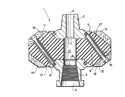
BRIEF DESCRIPTION OF THE DRAWING


A pref~r, ed embodiment of this invention is described below with reference to the
accompanying drawing which illustrates one form of shock absorber in cross-section.


DETAILED DESCRIPTION OF THE DRAWING


As shown the shock absorber (I) consis~s of a pair of components (2) and (3) one adapted
for connection to a drilling head and the other to the first drill rod of a drill string for a
borehole drill bit. The components have an axial passageway (4) therethrough.


The components have inclined faces (5) and (6) which enable their oppositely disposed ends
(7) and (8) to be countersunk into a resilient member in the form of a block (9) of elastomeric
material. This material is preferably polyurethane. The block also has an axial passage (10)
therethrough. The peripheral corners of the block (9) are chamfered to provide surfaces (Il)

and (12) against which rigid rings (13) and (14) seat. These rings are bored to receive bolts
(15) which extend through holes (16) through the block (9) so that each ring is bolted to the
component on the opposite side of the block (9). That is, ring (13) is secured to component
(3) and ring (14) is secured to component (2).


21207~8
- 5 -


Spacer sleeves (17) are provided in the holes (16) around the bolts (15).


The assembly forms a compact unit which can readily transmit torque and which will absorb
axial shocks applied through the drill string in use.


It will be appreciated that this invention is not limited to the particular example described.
Variations may be made and in particular the resilient member need not be of the shape
described but can be a flat ring.


It will be appreciated that the securing means des~i-iLed above as being bolts is not the only
suitable means for securing the components togell,er. It is quKe possible to have pins and
plates or washers which are welded in position. Due to the angle of the pins through the
block of material it will not be necessary to weld the inner ends of the pins, and plates around
the outer ends can be welded in position. It will in most cases however be advantageous
to have the inner ends of the pins also welded in position.


Representative Drawing
A single figure which represents the drawing illustrating the invention.
Administrative Status

For a clearer understanding of the status of the application/patent presented on this page, the site Disclaimer , as well as the definitions for Patent , Administrative Status , Maintenance Fee  and Payment History  should be consulted.

Administrative Status

Title Date
Forecasted Issue Date 1999-03-30
(22) Filed 1994-04-07
(41) Open to Public Inspection 1994-10-28
Examination Requested 1995-10-10
(45) Issued 1999-03-30
Deemed Expired 2002-04-08

Abandonment History

There is no abandonment history.

Payment History

Fee Type Anniversary Year Due Date Amount Paid Paid Date
Application Fee $0.00 1994-04-07
Maintenance Fee - Application - New Act 2 1996-04-08 $50.00 1996-02-12
Maintenance Fee - Application - New Act 3 1997-04-07 $50.00 1997-01-08
Maintenance Fee - Application - New Act 4 1998-04-07 $50.00 1997-11-13
Final Fee $150.00 1998-12-21
Maintenance Fee - Application - New Act 5 1999-04-07 $75.00 1999-02-04
Maintenance Fee - Patent - New Act 6 2000-04-07 $75.00 1999-12-07
Owners on Record

Note: Records showing the ownership history in alphabetical order.

Current Owners on Record
GIEN, BERNARD LIONEL
Past Owners on Record
None
Past Owners that do not appear in the "Owners on Record" listing will appear in other documentation within the application.
Documents

To view selected files, please enter reCAPTCHA code :


To view images, click a link in the Document Description column. To download the documents, select one or more checkboxes in the first column and then click the "Download Selected in PDF format (Zip Archive)" or the "Download Selected as Single PDF" button.

List of published and non-published patent-specific documents on the CPD .

If you have any difficulty accessing content, you can call the Client Service Centre at 1-866-997-1936 or send them an e-mail at CIPO Client Service Centre.


Document
Description 
Date
(yyyy-mm-dd) 
Number of pages   Size of Image (KB) 
Cover Page 1995-06-08 1 88
Abstract 1995-06-08 1 42
Claims 1995-06-08 2 124
Drawings 1995-06-08 1 87
Representative Drawing 1998-08-25 1 37
Representative Drawing 1999-03-22 1 17
Description 1998-09-16 4 100
Claims 1998-09-16 2 50
Drawings 1998-09-16 1 27
Description 1995-06-08 4 273
Cover Page 1999-03-22 1 47
Correspondence 1998-12-21 1 29
Fees 1997-11-13 1 27
Fees 1999-02-04 1 23
Prosecution Correspondence 1995-10-10 1 35
Office Letter 1995-11-03 1 37
Prosecution Correspondence 1998-04-24 2 61
Examiner Requisition 1998-02-06 2 44
Fees 1997-01-08 1 29
Fees 1996-02-12 1 29