Note: Descriptions are shown in the official language in which they were submitted.
2129614
COILED TUBING CONCENTRIC GAS LIFT ASSEMBLY
Background of the Invention
The present invention is directed to a coiled tubing concentric gas lift assembly
which is tubing retrievable, flexible, spoolable and provides a bore therethrough
5 allowing passage of well tools.
It is known, as disclosed in U.S. Patent No. 5,170,815 to provide removable and
flexible gas lift valves internally mounted in a coiled tubing. It is also known, as
disclosed in copending patent application Serial No. 2, 127, 013,
filed June 29, 1994, entitled "Coiled Tubing Wireline Retrievable
10 and Selective Set Gas Lift Assembly", to provide a flexible gas
lift valve in a coiled tubing which can be installed and removed
by wireline for allowing the passage of other well tools through
the coiled tubing.
The present invention is directed to a flexible gas lift valve assembly in a coiled
tubing which is positioned concentrically in the coiled tubing to provide an open bore
15 coaxially therethrough which is in communication with the bore of the coiled tubing
thereby allowing wireline work to be performed through the gas lift valves, such as
bottom hole surveys including pressure and temperature measurements, without
removing the gas lift valves. The present invention also provides gas lift valves in
which the coaction between the valve element and valve seat is guided and supported
20 and in which the gas lift valves may include injection ports if desired.
0341997
~'
2129614
`~ Summary
The present invention is directed to a flexible spoolable coiled tubing gas lift
valve connected in a coiled tubing having a bore. A longitudinal flexible gas lift valve
includes a circular housing having first and second ends connected in a coiled tubing
and the housing has an outside diameter substantially equal to the outside diameter of
the coiled tubing. An inside diameter of the housing is substantially equal to the inside
diameter of the coiled tubing. The housing includes an axial bore therethrough in
coaxial communication with the bore of the coiled tubing for allowing the passage of
well tools through the gas lift valve. The housing also includes a port between the first
and second ends which extends between the inside and the outside of the housing. A
movable valve element and a valve seat are provided within the inside diameter of the
housing in communication with the port and the valve element is controlled by a gas
con~ining compartment. The valve element and the valve seat are preferably
eccentrically positioned in the housing.
Yet a further object of the present invention is wherein the housing includes a
check valve eccentrically located and in communication with the valve seat.
Still a further object of the present invention is wherein seal means is provided
between the movable valve element and the housing. In one embodiment the seal
means is a bellows.
Still a further object of the present invention is wherein the valve element is
laterally supported and guided by the inside diameter of the housing.
A still further object of the present invention is the provision of a gas lift valve
in which the valve and the valve seat are coaxially positioned within the inside diameter
of the housing and the valve element may include a plurality of injection ports
positioned downstream of the valve seat.
-2-
. ~
2129614
Yet a still further object is wherein the valve element is
laterally supported and guided by the inside diameter of the
housing on both sides of the valve seat.
A further object is the provision of a check valve having a plurality of openings
in the housing and a circular resilient check element covering said openings andsecured to the valve element.
Other and further objects, features and advantages will be apparent from the
following description of presently preferred embodiments of the invention, given for the
purpose of disclosure, and taken in conjunction with the accompanying drawings.
Brief Description of the Draw~ngs
Figs. ~A and lB are continuations of each other and form an elevational view,
in cross-section, of one form of the present invention shown in the closed position and
in a spooled position,
Figs. 2A and 2B are continuations of each other and form an elevational view,
in cross section, of the gas lift valve of Figs. lA and lB but shown in an open position,
Fig. 3 is a cross-sec-tional view taken along the line 3-3 of Fig. 2A,
Fig. 4 is a cross-sectional view taken along the line 4-4 of Fig. 2B,
Fig. 5 is a cross-sectional view taken along the line 5;5 of Fig. 2B,
Fig. 6 is a fragmentary view taken along the line 6-6 of Fig. 2B,
Fig. 7 is an alternate embodiment of seal means positioned in the oval of Fig. 2B,
Figs. 8A and 8B are continuations of each other and form an elevational view,
in cross section, of another form of the present invention shown in the closed position
and in a spoolable position,
0341997 -3-
s~ .
2129614
Figs. 9A and 9B are continuations of each other and form an elevational view,
in cross section, of Figs. 8A and 8B but in the open and unspooled position,
Fig. 10 is a cross-sectional view taken along the line 10-10 of Fig. 9A,
Fig. 11 is a cross-sectional view taken along the line 11-11 of Fig. 9B,
Fig. 12 is a cross-sectional view taken along the line 12-12 of Fig. 9B,
Fig. 13 is a cross-sectional view taken along the line 13-13 of Fig. 9B, and
Fig. 14 is a cross-sectional view taken along the line 14-14 of Fig. 9B.
Des. l;~l,ion of the Prt:r~rl~(l Embo-limf~nt
The present invention will be described as various individual types of gas lift
valve assemblies for particularly pointing out the claimed invention. However, it is to
be understood that each coiled tubing may include one or more of the gas lift assemblies
of the present invention vertically connected in the coiled tubing and spaced from each
other.
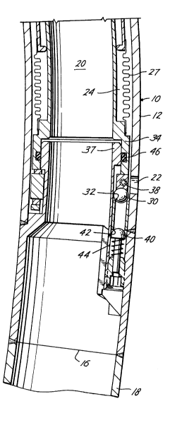
Referring now to the drawings, and particularly to Figs. lA and lB, and 2A and
2B, the reference numeral 10 generally indicates the longitudinally flexible gas lift valve
of the present invention which includes a circular housing 12 having a first end 14 and
a second end 16 connected in a coiled tubing 18, such as by welding. Preferably, the
housing 12 has an outside wall thickness and an outside diameter substantially equal
to the thickness and outside diameter of the coiled tubing 18. The housing 12 also
includes an axial bore 20 therethrough in communication with the bore of the coiled
tubing 18 for allowing the passage of well tools through the coiled tubing 18 and the
gas lift valve 10. The housing 12 also includes a port 22 for the admission of gas from
0341997 -4-
2 1 296 1 4
the annulus around the outside of the housing 12 which is injected into the bore 20 as
best indicated by the arrows in Fig. 2B for lifting fluids therein.
The gas lift valve 10 is normally biased to a closed position by a gas charged
compartment 24 acting on one or more bellows 26 and 27. The gas compartment 24
5 is charged through a dill valve 28 such as by air or nitrogen. A movable valve element
such as a ball 30 and a seat 32 are provided in the housing 12 in communication with
the port 22. The gas charged compartment 24 acts to seat the valve element ball 30 on
the seat 32 by being connected to a valve element extension 34. For opening the valve
10, lifting gas is injected into the port 22, acts on the exterior of the bellows 27 to
10 contract the bellows 27, lifts the ball valve element 30 and allows the gas to pass
through the valve seat 32 into the bore 20.
The valve 10 is advantageous in that it is longitudinally flexible and spoolable
and is shown in the spooled position in Figs. lA and lB. The valve 10 is flexible in
that the housing 12 may bend, and, of course, the bellows 26 and 27 are longitudinally
15 flexible. A flexible wire mesh 36 is provided adjacent the bellows 26 which may be a
rubber flexible wire mesh for protecting the bellows 26 from fluids in the bore 20 but
still allow longitudinal flexibility. Also, the housing 12 of the valve 10 is concentric
providing a large axial bore 20 therethrough for allowing wireline work to be performed
through the coiled tubing 18 and gas lift valves 10 as well as providing m~xim~l flow
20 area in the coiled tubing string.
Prior art concentric valve elements and valve seats have been proposed in the
past but they resulted in erratic valve operation because the ratio of the operating
bellows effective area to the injection port size of the valve could not be maintained
0341997 -5-
2129614
because of excessive wear and mi~lignment between the valve stem and seat. The
present invention overcomes this problem by moving the valve element 32 and the valve
seat 34 off of the center line of the valve 10 and eccentrically mounting them within the
valve housing 12. In addition, it is noted that the valve element extension 34 is slidable
5 against an inner wall 36 of the valve housing 12 thereby providing guidance and
support for the valve element 30 which is supported from a roll pin 38 (Figs. lB and
5) to provide a floating valve element which sealably mounts on the valve seat 32.
A check valve 40, preferably spring loaded, is provided in the housing 12
eccentrically located and in communication with the valve seat 32 for normally seating
10 on a seat 42 preventing tubing fluids from flowing out through an opening 44 and
though the port 22 but allowing the reverse flow of gas lift fluids.
Referring to Figs. lB and 2B, a seal 46 is provided between the valve element
extension 34 and the inner wall 36 of the housing. In some cases, the effective diameter
of the seal 46 may be made equal to the effective mean diameter of the bellows 26 for
15 balancing out the effect of tubing pressure in the bore 20, while in other cases, the
diameter of the seal 46 may be varied depending upon the desirability of obt~ining
effective action of the tubing pressure on the bellows. While the seal 46 shown in Figs.
lB and 2B is a conventional resilient seal, in another embodiment, as best seen in Fig.
7, the seal 46a may be a bellows.
In Figs. lA and lB, the valve 10 is shown spooled upon a coiled tubing reel (not
shown) and in the closed position. In Figs. 2A and 2B, the coiled tubing and valve is
shown in a position in a well and in the open position in which lift gas is being injected
through the valve 10 and upwardly through the bore 20.
0341997 -6 -
2129614
Other and further embodiments will be further described wherein like parts to
those numbered in Figs. lA through 7 will be similarly numbered with the addition of
the suffix "a".
The valve 10a, shown in the closed and spooled position in Figs. 8A and 8B and
5 in the open and extended position in Figs. 9A and 9B includes a housing 12a secured
in a coiled tubing 18 having an axial bore 20a therethrough. A gas compartment 24a
acts against bellows 26a and 27a to normally bias a concentric valve element 30a onto
a concentric seat 32a. The housing 12a includes a port or ports 22a for admitting gas
from the annulus around the housing 12a to act on the bellows 27a in a direction for
10 retracting the valve element 30a from the valve seat 32a. First, it is noted that the
valve 10a, unlike the valve 10 in which the valve element 30 in valve seat 32 were
eccentrically positioned in the housing 12, contains a concentric valve element 30a and
concentric valve seat 32a. However, the valve stem, unlike prior art concentric valves,
is guided and laterally supported at two places for overcoming the problems of prior art
15 valves. Thus, the valve element 30a includes a valve element extension 34a which
engages an inner wall 36a at a position above the valve seat 32a. In addition, the valve
element 30a includes a lower extension 44 which engages a housing lower guide 46
which is positioned below the valve seat 32a. Thus, as the valve element 30 moves, it
is laterally supported and guided, both above and below the valve seat 32a, thereby
0 ensuring accurate and aligned m~t.ing of the valve element 30a with the valve seat 32a.
Thus, while the valve 10a is concentric, it is securely centralized to provide a
good mating relationship between the valve element and valve seat.
0341997 - 7-
2129614
Valve 10a also includes a spring 60 acting against the movable valve seat 32a
which helps bias the valve to a closed position.
It is also to be noted, that, if desired, the lower extension 44 includes a plurality
of injection ports 50 which, when the valve is in the open position, as best seen in Fig.
5 9B, regulates the injection pressure flowing into the bore.
Valve 10a also includes a check valve which includes a plurality of ports 52 in
the housing 12a and a circular resilient check element 52 secured to the valve element
30a. When the valve 30a is closed, as best seen in Fig. 8B, the resilient check valve 52
covers and closes the ports 52. However, when the valve 30a is moved to the open
10 position, the resilient check 54, which includes a lower tapered end, allows inward
passage of gas through the ports 52, through the valve seat 32a, and out the injection
pressure ports 50.
The valve 10a is also flexible, similar to the valve 10, and in addition, has a
m,qximum flow area bore 20a which allows wireline work to be performed therethrough
15 without removing the valves.
The present invention, therefore, is well adapted to carry out the objects and
attain the ends and advantages mentioned as well as others inherent therein. While
presently preferred embodiments of the invention have been given for the purpose of
disclosure, numerous changes in the details of construction and arrangement of parts,
20 will readily suggest themselves to those skilled in the art and which are encompassed
within the spirit of the invention and the scope of the appended claims.
03419~7 -8-