Note: Descriptions are shown in the official language in which they were submitted.
W093/17743 PCT/US93/01857
,. ~ .
21 3~827
"POWDER NEBULIZER APPARATUS AND METHOD OF
NEBULIZATION"
BACKGROUND OF THE INVENTION
Field of the Invention
The present invention relates to a powder nebulization
method and a powder nebulizer apparatus usea in respiratory
therapy and, in particular, to a continuously connected,
continuous flow powder nebulizer useful in respiratory
therapy to deliver powdered medications.
Descri~tion of the Related Art
Critically ill patients requiring mechanical ventilation
are often victims of respiratory distress syndrome, status
asthmaticus and pulmonary infections. Treatment of these and
other severe respiratory conditions includes medications
delivered directly to the lungs of the patient.
Respiratory delivery of medication for these conditions
is preferable to oral, intravenous and subcutaneous delivery
because it is non-invaslve, permits rapid action of medicant,
re~uires a relatively small dosage, is not filtered through
the liver of the patient, and produces a low incidence of
systemic side effects.
Nebulized or aerosolized solutions are the preferred
method of respiratory delivery of medication; when fragmented
into small particles, medicants are more efficiently
deposited near sites of medicant activity in the lung.
~V093/l77~3 2 1 3 0 8 2 7 PCT/US93/0l8s,
Respiratory= medications may be delivered to the lungs
the patient as an aerosol of a liquid or a powder. Clinical
aerosols are currently generated by iet or ultrasonic
nebulizers, metered dose inhalers (MDI ) and dry powdered
inhalers.
There are two types of nebulizers for the delivery of
liquid medication to the lungs: jet nebulizers and ultrasonic
nebulizers. In conventional jet nebulizers, compressed gas
from a compressor or hospital air line is passed through a
narrow constriction know as a jet. This creates an area of
low pressure, and liquid medication from a reservoir is drawn
up through a feed tube and fragmented into droplets by the
airstream. Only the smallest drops leave the nebulizer
directly, while the majority impact on baffles and walls and
are returned to the reservoir. Consequently, jet
nebulization takes several minutes to complete, depending
upon the initial volume.
Important disadvantages of nebulizers include low lung
deposition related to the use of tidal breathing. A
substantial portion of the dose used in a jet nebulizer is
retained permanently as a dead or residual volume on baffles
and internal walls of the nebulizer chamber and cannot be
released. Generally only 2-10% of the dose placed in the
nebulizer ever reaches the lung. The consequences are a
higher drug dosage and longer administrative time, along with
the associated cost and risk of contamination.
The second type of aerosol generator is a metered dose
W093/l7743 ~ 3 ~ ~ ~ 7 PCT/US93/01857
.
inhaler (MDI), which delivers a bolus of more concentrated
drug aerosols than the solution commonly available for
nebulizers. For optimal effect, MDI delivery systems require
proper administration technique, which includes coordinated
actuation of aerosol delivery with inhalation, a slow
inhalation of 0.5-0.75 liters per second, a deep breath
approaching inspiratory capacity inhalation, and at least 4
seconds of breath holding.
Many patients find it difficult to properly administer
medication with an MDI, especially during acute exorbation.
An article which appeared in Eur. J. Respir. Dis., 68(5), 332
(1986), entitled ~Bronchodilator Affects of a Fenoterol Meter
Dose Inhaler and Fenoterol Powder in Asthmatics with Poor
Inhaler Technique,~ described test findings showing that the
effectiveness of bronchodilator medication, when delivered
with an MDI, is dependent on good MDI technique. The article
suggested that delivery of medication in a powdered form is
more reliable for patients who do not exercise proper MD
technique.
MDI~s can be equipped with devices that automatically
couple actuation to inspiratory effort, thus eliminating the
need for coordinating hand action with inhalation. Devices
such as spacers and holding chambers also decrease partial
velocity and reduce the number of large particles. Both of
these features reduce oral pharyngeal and large airway
deposition with a consequent reduction in systemic
absorption. Deposition of aerosols from an MDI with a spacer
W093/t7743 2 1 3 0 8 2 7 PCTtUS93/0l8s7
or holding chamber is similar and perhaps better than the
deposition of a properly used MDI alone.
Advantages of the MDI include deposition of 10-15~ of
the metered dose with consequent short treatment time, low
cost and increased convenience. However, MDI~s cannot be
used by patients requiring mechanical ventilation. Other
disadvantages include the need for patient cooperation, the
practical limitations and inconveniences associated with
increased dosing requirements due to the typically small
dosages administered with an MDI, the limited number of
currently available drugs, and the dependence on
fluorocarbons for aerosol generation.
Others have recognized the need for new inhalation
devices such as modified dry powder inhalers to replace use
of MDI~s due to environmental concerns related to the use of
fluorocarbons. See ~Today's Treatment of Airway
Obstruction...and Tomorrow~s?~ Flenley, D.C., Respiration, 55
Suppl. 2, 4 (1989).
The third type of aerosol generator is a dry powdered
inhaler. Dry powdered inhalation devices currently in use are
the Spinhaler, the Rotahaler, the Turbuhaler and the disc
inhaler. Dry powdered inhalers are breath actuated and
usually require a higher inspiratory flow rate than that
required for an MDI or a nebulizer. Flow rates of 1-2 liters
per second are usually considered optimal, although flow
rates as low as 0.5 liters per second may be effective for
some dry powdered inhalers.
W O 93/17743 . '' ; ' 2 ~ P~r/US93/01857
Advantages of dry powdered inhalers include relative
ease of a~mini~tration and the fact that they do not require
fluorocarbon propellants. When a dry powdered inhaler is
used properly, deposition appears to be similar to that of a
properly used MDI.
However, powdered inhalers are limited by the dose they
can provide and by the number of drugs currently available.
Only terbutaline, salbutamol, dexamethasone and chromolyn
sodium are available in powder form.
All conventional powder inhaler delivery systems utilize
single dose capsules except the Turbuhaler for administration
of terbutaline. While several devices have been developed
which permit preloading of several single dose capsules,
neither these devices nor the Turbuhaler have eliminated the
other disadvantages of conventional powdered inhalers. See
"A New Inhalation System for Bronchodilatation. Study of
the Acceptance of the Ingelheim M Inhaler in Chronic
Obstructive Respiratory Tract Diseases,~l Mutterlein, B.
Schmidt, ~., Fleisher, w., and Freund, E., Fortschr. Med.,
April 15, 108(11), 225 (1990)i "In Vivo Evaluation of the New
Multiple Dose Powder Inhaler and the Rotahaler Using the Gama
Scintigraphy," Vidaren, M., Paronen, P., Vidaren, P., Vainir,
P., and Nuutinen, J., Acta. Pharm. Nord., 2(1), 3 (1990);
~Clinical Use of Dry Powder Systems," Crompton, G . K., Eur. ~ .
~espir. Dis. Suppl ., 122, 96 (1982).
Other disadvantages of dry powdered inhalers include the
following: a) they are usually not particle size-selective
WO93/177~3 2 1 3 0 8 2 7 PCT/US93/0l857
and thus heavy oral pharyngeal deposition may occur; b) high
humidity environments may cause clumping of the particlesi
and c) dry powdered inhalers cannot be used in ventilatory
circuits.
Currently available devices for delivery of powdered
medications in respiratory therapy do not employ nebulization
technology.
The use of compressed air powered jet mills as a powder
generator for inhalation experiments is disclosed in "Use of
a Jet Mill for Disbursing Dry Powder for Inhalation Studies,"
Cheng, Y.S., Marshall, T.C., Henderson, R.R., and Newton,
G.J., Am. Ind. ~ya. Assoc. ~., 46(8), 449 (1985~. The jet
mill consisted of an elongated channel, one material delivery
jet, and two high speed air jets. Powder fed into the
channel was disbursed by turbulence and centrifugal forces.
The powder used in the inhalation experiments consisted of
dye materials to be tested for toxicity. A flow rate of 400
liters per minute was maintained. The article does not
address nebulization of powdered medication for purposes of
respiratory therapy.
U.S. Patent 4,232,002 discloses procedures for
administering antihistamines. Methods disclosed include
inhalation by a patient of mist, nebulized spray, or a cloud
of fine solid particles. Products for delivery of medication
include pressurized canister inhalers, portable dry powder
insuffilators using capsules, and nebulizers. The only dry
powder delivery system described is a dry powder inhaler
WO93/17743 ' 2 1 3 0 ~ 2 7PCT/US93/0l857
using capsules of dry powder in single dose units. The
delivery method described involves puncturing a capsule of
dry powder medication which is disbursed by means of a
turbomixer to be inhaled through a mouth piece. This patent
does not address continuous flow or continuous delivery of
inhalable medication. It does not enablingly teach or
address jet nebulization of powdered solid medications, and
does not teach a nebulizer vial which connects to a nebulizer
to provide a device for introducing continuous flow.
U.S. Patent 3,669,113 discloses a method and device for
dispensing powdered medication from a perforated container by
rotating the container by pneumatic means and causing the
axis of rotation of the container to precess and describe a
path of precession which is contained within a generally
conical surface of a precession. The mechanisms described
are based on varying shaft and bearing configurations. The
method of this patent is said to be especially well suited to
delivery of particles less than 80 microns in diameter. The
patent does not address jet nebulization, continuous flow or
continuous nebulization.
Recent developments in respiration therapy involve
aerosolization and delivery of nebulized liquids on a
continuous basis over several hours. Such delivery
stabilizes the effects of the medication over time, reduces
respiratory personnel support time, and reduces the chances
of respiratory circuit contamination.
In our prior co-pending U.S. Patent Application NC .
W O 93/17743 2 1 3 0 8 2 7 PC~r/US93/01857
07/729,518, filed July 12, 1991, a liquid nebulizer system is
disclosed comprising a nebulizer attachable nebulizer vial, a
large supply vessel, and a fluid delivery system, to be used
with a conventional liquid nebulizer. The liquid nebulizer
system provides for continuous delivery of liquid medication
from a large supply vessel into the nebulizer vial which is
attached to a conventional nebulizing apparatus, permitting
continuous delivery of nebulized liquid medication. The
disclosure of such prior copending application is hereby
incorporated herein by reference.
It would be a significant advance in the art to combine
the technology of nebulization systems with the efficiency of
dry powdered inhaler systems.
Accordingly, it is an object of the present invention to
provide a method and apparatus for continuous respiratory
delivery of nebulized powdered medication.
It is another object of the invention to provide a
method and apparatus for respiratory delivery of powdered
medication which may be used in ventilatory circuits.
It is another object of the invention to provide a
method and apparatus which overcome the disadvantages
associated with currently available respiratory medicant
delivery systems.
These and other objects and advantages of the present
invention will be more fully apparent from the ensuing
disclosure and appended claims.
W093/17743 , , PCT/US93/01857
~ 2 i 3~7
SU~M~RY OF THE INVENTION
The present invention alleviates the disadvantages of
conventional administration of respiratory medications. The
invention provides for administration of respiratory
medication with less patient coordination than that required
by an MDI or dry powdered inhaler, and can be used in
ventilatory circuits. No inspiratory flow rate is required
of patients. A carrier flow rate as low as .5 to 2 liters
per minute can be accommodated by the present invention, as
opposed to the 6 to 8 liters per minute flow rate required by
a liquid nebulizer apparatus.
The apparatus of the present invention operates without
the baffling system which is used in li~uid nebulization
systems, thereby enabling a larger percentage of medication
to be delivered to the patient instead of being retained in
the apparatus. The percentage of the originally provided
medication which is actually delivered to the patient by the
apparatus and method of the present invention is typically
greater than 20~. The size of particles produced by the
invention is determined by the intrinsic physical form, e.g.,
molecular structure of the medicament species, not by the
specific apparatus configuration and methodology of the
nebulizer as in liquid nebulizer systems. Higher drug
dosages can be obtained by use of the present invention than
is possible with conventional respiratory medication delivery
systems.
In one aspect, the present invention relates to a method
W093/17743 2 1 3 0 8 2 7 PCT/USg3/01857
of forming a solid particle dispersion in a carrier gas
stream, comprising the steps of:
(a) providing a generally conical-shaped or funicular
receptacle containing particulate solid to be dispersed;
(b) directing a jet of carrier gas downwardly toward
the lower extremity of the generally conical-shaped or
funicular receptacle to entrain particles of the
particulate solid in the gas; and
(c) discharging particulate solids-containing gas from
the receptacle.
In a particularly preferred embodiment of the method of
the present invention, the gas stream directed at the
particulate solid is passed through a first nozzle, then
expanded and passed through a second nozzle where an
entrainment structure channels gas from the conical-shaped
receptacle to the jet structure, increasing total gas flow
and aiding in the production of a gas jet flow stream of
desired velocity and pressure characteristics. The
entrainmen~ structure comprises a chamber defining a plenum,
with an entrainment port communicating in gas flow
relationship with the interior volume of the housing, and
with an outlet port communicating with the second nozzle to
cooperatively form a jet structure therewith.
In another aspect, the present invention relates to a
continuous flow powder nebulizer medicant delivery system
comprising a jet nebulizer including a conical nebulizer
receptacle. The nebulizer receptacle provides a reservoir
WO93~17743 - 2 t 3 ~ PCT/US93/01857
for powdered medication with a multiple dose capacity,
permitting continuous delivery of medication rather than a
single breath dose or periodic single doses. The present
invention may be used with a ventilator circuit to deliver
nebulized powdered medication and gas to patients via an
endotracheal tube when necessary for critically ill patients.
A mouthpiece, mask or other proximal attachment is used to
deliver nebulized powdered medicant to voluntary patients.
More specifically, the nebulizer device of the present
invention comprises a nebulizer housing having a generally
conical-shaped or funicular lower housing portion defining an
interior volume enclosed by the housing, and a gas jet
member, e.g., a nozzle element, at the upper portion of the
housing, generally coaxially aligned with the cone-shaped or
funicular lower portion. The gas jet member extends through
the housing, with an upper inlet portion coupleable to a
suitable source of compressed carrier gas, and a lower
portion of the gas jet member forming a nozzle or discharge
structure for directing gas downwardly to the lower extremity
of the conical-shaped or funicular lower portion of the
nebulizer housing. At the upper portion of the nebulizer
housing, in transversely outwardly spaced relationship to the
gas jet member, is an exit port, for discharge of solids-
containing carrier gas from the nebulizer housing to an
exterior treatment locus. For example, the exit port may be
suitably coupled to a ventilator or breathing circuit,
comprising connecting tubing, as described hereinabove.
W093/17743 2 1 3 0 8 2 7 PCT/US93/0l8S7
As used herein, the term ~transverse~ refers to the
direction generally perpendicular to the central axis defined
by the conical-shaped or funicular lower portion of the
nebulizer housing.
In a particularly preferred embodiment, the above-
described gas jet member is coaxially disposed in closed flow
communication with a second gas jet member, with the second
gas jet member having an upper portion defining a receiving
volume for receiving carrier gas discharged from the nozzle
or discharge end of the first gas jet member. The receiving
volume is of significantly greater transverse cross-section
than the discharge passage of the first gas jet member. The
second gas jet member defines a lower discharge passage
(nozzle portion) which is of substantially reduced transverse
cross-section, relative to the receiving volume. By this
arrangement, the compressed carrier gas is discharged from
the first gas jet member into the receiving volume of the
second gas jet member, thereby undergoing expansion,
following which the gas is discharged in a high velocity jet
from the nozzle portion of the second gas jet member disposed
beneath the first gas jet member. Gas exiting the second gas
jet member passes through an entrainment structure wherein
additional gas, which is channeled from the nebulizer
receptacle into the entrainment structure through an
entrainment port, is entrained in the gas stream being
discharged from the second gas jet member. Entrainment of
gas from the nebulizer receptacle increases circulatory flow
W093/17743 ~ - ~- 2 1 3 0 8 2 7 PCT/US93/01857
by producing a swirling effect wlthin the nebulizer
receptacle, and increases the homogeneity of the nebulized
particulate-containing gas. The resultingly discharged high-
velocity gas stream then engages the powdered medicament in
the lower portion of the nebulizer housing, which is of
progressively decreasing transverse cross-section. As a
result, there is achieved a high extent of solids entrainment
in the carrier gas stream, as discharged from the nebulizer
housing through the exit port.
The operation of the nebulizer device of the present
invention is based on a number of gas physics laws. One such
principle is the Bernoulli principle, which states that where
the forward velocity of a gas increases, its lateral wall
pressure decreases with a corresponding increase in forward
pressure. The jet structure in the nebulizer of the present
invention utilizes this principle.
use of two jets in a preferred embodiment of the
nebulizer of the present invention, one above the other,
forms a type of proportional amplifier, yielding greater
pressure from a lower flow rate. The first jet, wherein the
gas flows through a pinhole or other nozzle-forming means,
causes a directed flow of carrier gas to issue from the jet.
As the gas leaves this jet, the flow is allowed to expand
laterally for a very small distance. The flow is then
directed into a second jet comprising a nozzle-forming means,
causing the flow to undergo a phenomenon described by
Toricelli's law, which states that as gas flow meets a
W093/17743 2 ~ 3 ~ ~ ~ 7 PCT/USg3/01857
restriction, the molecules must travel faster in a forward
direction than they did previously. In a preferred
embodiment of the present invention, the accelerated gas flow
produced according to Toricelli~s law is further accelerated
by entrainment of gas from the nebulizer receptacle in the
gas flow by means of an entrainment structure. The principle
upon which such entrainment is based is Venturi's law of
air/liquid entrainment.
Simply stated, gas is directed by the nebulizer through
a jet where the gas flow accelerates; in the preferred
double-jet system of the invention, this accelerated gas flow
then partially re-expands after exiting the jet, and flows
into a second jet which further increases the pressure. The
pressure of the gas being discharged from the second jet
entrains gas through the entrainment structure which
increases the circulatory flow of the carrier gas. In either
case, the pressurized gas is directed down into the nebulizer
vial with a "V" or cone- shaped apex containing powdered
medication. This creates a swirling effect in the
receptacle, causing the medication to rise to the top of the
nebulizer receptacle for efficient entrainment in the carrier
gas and subsequent delivery to the patient.
B~ TEF DESCRIPTION OF THE DRAWINGS
Figure 1 is a schematic representation of a patient
receiving respiratory support and continuous medication via a
continuous flow nebulizing device connected to an
14
WO93/17743 . PCT/US93/01857
~ 2~ 30~27
endotracheal tube and a ventilator.
Figure 2 is a perspective view of a nebulizer housing
and supporting system comprising a nebulizer upper portion,
nebulizer receptacle and influent gas flow regulating and
supply devices.
Figure 3 is a cross section of a powder nebulizer device
comprising an influent port, outlet port, and jet-producing
structure.
Figure 4 is a cross section of a powder nebulizer device
comprising an influent port, outlet port, ~et-producing
structure, and entrainment structure.
DFTAI~ED DESCRIPTION OF THE INVENTION,
AND PREFERRED EMBODIMENTS THEREOF
The present invention provides a method and apparatus
which overcome the disadvantages associated with currently
available respiratory medicant delivery systems. The present
invention requires less patient coordination than that
required by an MDI or dry powdered inhaler, requires no
inspiratory flow rate from patients, and can accommodate flow
rates for the carrier gas as low as .5 to 2 liters per
minute.
The present invention provides a method and apparatus
for continuous respiratory delivery of nebulized powdered
medication. In addition, the present invention provides a
method and apparatus for respiratory delivery of powdered
medication which may be used in ventilatory circuits. This
represents an advance in the state of the art; no currently
W093/17743 2 1 ~ 0 8 2 7 PCT/US93/Ot857
available devices for delivery of powdered medications in
respiratory therapy provide for continuous delivery of
nebulized powdered medication or for use with ventilatory
circuits.
In this description, the term ~'proximalN is used to
indicate the segment of the device normally closest to the
patient when it is being used. The term Udistal'' refers to
the other end. Herein the term Unebulizing deviceU is
defined to be a nebulizing unit or instrument used to
aerosolize powdered medication for delivery to a patient.
The term Unebulizer receptacle~l is defined to be that portion
of a nebulizing device which comprises a container for a
reservoir for powdered medication to be nebulized. The term
Unebulizer upper portion" is defined to be the non-nebulizer-
receptacle portion of the nebulizing device which comprises
at least a portion of the nebulizing mechanism. Reference is
now made to the embodiments illustrated in Figures 1-4.
As seen in Figure 1, a patient 30, undergoing
respiratory therapy, is fitted with an endotracheal tube 24.
The proximal trunk end 18 of a "Y"-shaped connector 32 is
insertably connected to a distal end 25 of endotracheal tube
24. Nebulizing device 48 is connected to arm 34 of "Y"-
shaped connector 32 via tube 22 which is interposed and
connected between exit port 21 of nebulizer device 48 and arm
34 of the UYu-shaped connector 32 at port 33. A distal end
35 of arm 34 is insertably connected to a proximal end 14 of
gas delivery tube 12. Gas delivery tube 12 provides the
16
W093/17743 - 2 ~ 3 0 8 2 7 PCT/US93/0l857
distal portion of inhalation respiratory pathway 26 and
connects to the output inhalation gas of a ventilator 10.
Ventilator 10 thereby supplies periodic, breath-sustaining
pulses of pressurized gas through tube 12 and through arm 34
of ~Y~-shaped connector 32 into endotracheal tube 24 and to
patient 30.
The other distal end 36 of "Y"-shaped connector 32
comprises a proximal portion of an exhalation respiratory
pathway 28 which further comprises tube 16 which returns
exhalation flow to ventilator 10. Many different ventilators
are known and available in the art. Generally, ventilators
which are currently used with nebulizers may be used with the
present invention.
Nebulizer device 48 receives a supply of nebulizing gas
from a flow meter 40 along a fluid pathway 26' which passes
through a tube 42 interposed and connected between flow
meter 40 and a top nebulizer inflow connecting tube 44~.
Flow meter 40 receives a pressurized gas from a gas source
44 through a connecting tube 42'. Gas pressure from gas
source 44 is sufficient to provide the volumetric flow for
which flow meter 40 is preset. Gas source 44 may comprise
pressurized oxygen or other breathable gas from the hospital
pressurized oxygen delivery system, from a tank of compressed
oxygen, a blender, directly from ventilator 10 or from other
sources of pressurized gases used in respiratory therapy.
Flow meters are well known and widely used in the art. Such
flow meters may comprise macro and vernier adjustable
~VO93/17743 2~ 3Q~ PCT/US93/0l857
controls for very accurate and precise gas flow settings.
Although oxygen is preferred for some selected medicants,
source 44 may supply oxygen blended with other gases.
Nebulizing device ~8 comprises nebulizer upper portion
20 and a nebulizer receptacle 50. Nebulizing device 48
nebulizes or aerosolizes powdered medication contained in
nebulizer receptacle 50 thereby producing a mist (particulate
solids-in-gas dispersion) which is carried to patient 30 by
influent flow of gas from ventilator 10 through pathway 26
and by nebulizing gas received from gas source 44.
As seen in Figure 2, nebulizing device 48 comprises
nebulizer receptacle 50 which is attached to nebulizer upper
portion 20. In a specific embodiment, the top of the
nebulizer receptacle 50 is 1.5 inches in diameter, the bottom
is 0.25 inches in diameter, and the nebulizer receptacle 50
measures 1.5 inches from tOp tO bottom. An end 68 of nozzle
66 is disposed above the surface of a reservoir 72 in the
bottom of the nebulizer receptacle 50.
While specific dimenslons and tolerances are
illustratively set forth herein in respect of the preférred
embodiments of the invention, it will be appreciated that the
specific size, design, dimensions, and tolerances, may be
varied widely within the broad scope of the present
invention, with the choice of a specific set of such design
parameters being dependent on the particular end use
application contemplated in a given instance. The present
invention may be embodied in the various embodiments
18
WO93/17743 2 1 3 0 8 2 7 PCT/US93/0l857
illustrated in our prior co-p~n~i ng u. s . Patent Application ===
No. 07/729,518, filed July 12, l99l, which is hereby
incorporated herein by reference.
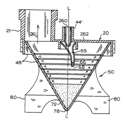
Figure 3 provides a sectional view of nebulizing device
48, comprising nebulizer upper portion 20 and nebulizer
receptacle 50. The following description of nebulizer upper
portion 20 is provided for a general understanding of the
interaction between nebulizer upper portion 20 and nebulizer
receptacle 50.
The nebulizer upper portion 20, as seen in Figure 3,
comprises a housing 262 which includes a nebulizer inflow
connecting tube 44l, a nozzle 260, and a second nozzle 66.
The jet structure comprising the nozzles may, as shown, be
positioned off-center relative to the centerline axis L-L of
the receptacle. In the broad practice of the present
invention, wherein single or multiple nozzle jet structures
may be employed, the jet structure may be offset to the
receptacle centerline (vertical axis) or the jet structure
may be coaxial with such central axis of the receptacle,
depending on the overall design, operation, and end use
application of the nebulizer. Pressurized gas which provides
the nebulizing high velocity gas stream for nebulization is
provided through nebulizer inflow connecting tube 44'. The
high velocity stream is produced by nozzle 260 and nozzle 66.
The pressurized gas is discharged from the first nozzle 260
into the receiving volume 65 of the second nozzle 66, thereby
undergoing expansion, following which the gas is discharged
19
WO93/17743 2 ~ 3 3 8 2 7 PCT/US93/0l857
in a high velocity jet from the end 68 of nozzle 66. The
resultingly discharged high-velocity gas stream then engages
the powdered medication in the lower portion of nebulizer
receptacle 50, which is of progressively decreasing
transverse cross-section. As a result, there is achieved a
high extent of solids entrainment in the gas stream, as
discharged into inhalation pathway 26~ via exit port 21.
While this description of the nebulizer upper portion 20
is for a single connecting tube 44l, nozzle 260, nozzle 66
and associated parts, the type, number, and structure of
inflow connecting tubes, nozzles, and associated nebulizer
parts may vary.
Nebulizer receptacle 50 has a conical-shaped or
funicular shape, is made from synthetic resinous material and
is preferably transparent or at least translucent for easy
monitoring of solids content by a respiratory technician or
other patient attendant. Various materials of construction
which are well known in the art are appropriate for the
nebulizer receptacle. They are usually of chemically-inert
thermoplastic such as polyolefins or polyvinyl chlorides.
Their selection and fabrication are well within the skill of
the art.
Apex 78 of the conical-shaped nebulizer receptacle 50
provides a containment structure for powdered medication
contained in nebulizer receptacle 50. A plurality of legs 80
provide a level support when nebulizer receptacle 50 is
disposed on a horizontal surface, to maintain powdered
=
WO93/17743 2 ~ 3 0 8 2 7 PCT/US93/01857
medication at the bottom of the nebulizer receptacle 50.
Figure 4 provides a sectional view of nebulizing device
148, comprising nebulizer upper portion 120 and nebulizer
receptacle 150. Numerals in Figure 4 have been
differentiated from numerals designating like parts in Figure
3 by adding 100 to each such numeral.
The nebulizer upper portion 120, as seen in Figure 4,
comprises a housing 362 which includes a nebulizer inflow
connecting tube 144~, a first nozzle 360, and a second nozzle
166. Pressurized gas is provided through nebulizer inflow
connecting tube 144~. The high velocity stream of gas for
nebulization is produced by nozzle 360 and nozzle 166. The
pressurized gas is discharged from the first nozzle 360 into
the receiving volume 165 of the second nozzle 166, thereby
undergoing expansion, following which the gas is discharged
into entrainment structure 167. As the high velocity gas
stream passes through entrainment structure 167, a resulting
below ambient pressure within entrainment structure 167
creates a sufficient pressure differential between
entrainment port 169 and nebulizer receptacle 150 to draw gas
from nebulizer receptacle 150 through entrainment port 169
and into entr~inm~nt structure 167 where the entrained gas is
added to the high velocity gas stream being directed toward
reservoir 172. The resultingly augmented gas stream exits
entrainment structure 167 through outlet port 170. The high
velocity gas stream thus discharged from jet structure 171
engages the powdered medication in the lower portion of
W093/17743 2 l 3~7 PCT/US93/ot8s7
nebulizer receptacle lSO, which ls of progressivel
decreasing transverse cross-section. As a result, there is
achieved a high extent of solids entrainment in the gas
stream, as discharged into inhalation pathway 126' via exit
port 121.
Best Mode For Carrvin~ Out The Invention
In a preferred aspect, the powder nebulizer apparatus of
the invention is generally configured as shown and described
with reference to Figures 3 or 4 hereof, and such nebulizer
device is utilized for delivery of dry powder medicament. In
a most preferred aspect, the nebulizer device is configured
as shown and described with reference to Figure 4 hereof.
In operation, such nebulizer device is provided with an
oxygen-containing carrier gas which is introduced into the
powder-containing receptacle of the device at a flow rate in
the range of from about 0.5 to 2 liters per minute, thereby
producing a solids-in-gas disperson which is flowed by
suitable connector structure from the nebulizer device to the
patient, to effect treatment of the patient with the powder
medicament.
Preferably, the nebulizer housing is formed of a
transparent or ~ransluscent polymeric material, e.g., of
thermoplastic construction, so that visual verification of
22
WO93/17743 2 1 3 0 8 2 7 PCT/US93/01857
the nebulization action and powder inventory in the reservoir
of the device is facilitated.
ndustrial A~licabilit~
The nebulizer device of the present invention is
usefully employed in the delivery of powdered medication to
the lungs for treatment of a patient. Such powdered
medicament delivery facilitates administration of the
treating agent where it is insoluble in suitable liquids for
conventional liquid aerosolization, and the dry powder form
of the delivered medicament enables lower fluid volumes to ~e
administered to the patient undergoing treatment.
Among the drugs which may be advantageously a~mi ni tered
by the nebulization device of the present invention are
terbutaline, salbutamol, dexamethasone, and chromolyn sodium.