Note: Descriptions are shown in the official language in which they were submitted.
213~61
Hydrocrac~inq of Heavy Hydrocarbon Oils With Heavy Hydrocarbon
Recycle
Backqround of the Invention
This invention relates to the treatment of hydrocarbon
oils and, more particularly, to the hydrocracking of heavy
hydrocarbon oils to produce improved products of lower boiling
range.
Hydrocracking processes for the conversion of heavy
hydrocarbon oils to light and intermediate naphthas of good
quality for reforming feed stocks, fuel oil and gas oil are
well known. These heavy hydrocarbon oils can be such
materials as petroleum crude oil, atmospheric tar bottoms
products, vacuum tar bottom products, heavy cycle oils, shale
oils, coal-derived li~uids, crude oil residuum, topped crude
oils and heavy bituminous oils extracted from tar sands. Of
particular interest are oils extracted from tar sands and
which contain wide boiling range materials from naphthas
through kerosene, gas oil, pitch, etc. and which contain a
large portion of material boiling above 524~C. These heavy
hydrocarbon oils contain nitrogen and sulphur compounds in
extremely large quantities and often contain excessive
quantities of organo-metallic cont~m;n~nts which tend to be
detrimental to various catalytic processes which may ;
sub~e~uently be carried out, such as hydrofining. Of the
metallic cont~'n~nts, those containing nickel and vanadium
are most common, although other metals are often present.
These metallic cont~m;n~nts, as well as others, are usually
present within the bituminous material as organo-metallic
compounds of relatively high molecular weight. A considerable
~uantity of the organo-metallic complexes are linked with
asphaltenic material and contain sulphur.
As the reserves of conventional crude oils decline, the
heavy oils must be upgraded to meet the demands. In this
upgrading, the heavier material is converted to lighter
fractions and most of the sulphur, nitrogen and metals must be
removed. This is usually done by means of a hydrocracking
process.
~ 2 2131261 ~
In catalytic hydrocracking, the mineral matter present in
the feed stock tends to deposit on the surface of the
expensive catalyst, making it extremely difficult to
regenerate, again resulting in increased production cost. The
non-catalytic or thermal hydrocracking process can give a
distillate yield of over 85 weight percent but in this
process, there is a very considerable problem of the formation
of coke deposits on the wall of the reactor which ultimately
plug the reactor and cause costly shutdowns.
It is known to recycle downstream heavy hydrocarbon -~
products in thermal hydrocracking processes for the purpose of
improving efficiency. For instance, Wolk, U.S. Patent No.
3,844,937, issued October 29, 1974 describes a process for
utilizing a high ash content in the hydrocracking zone fluid
e.g. in the range of 4-10 weight percent as a means for
preventing the formation of coke in the hydrocracking zone.
In order to achieve this ash content in the fluid, a recycle
of heavy hydrocarbons from a hot separator was used and as a ~ -
part of this recycle, the heavy hydrocarbons from the hot
separator were passed through a cyclone or through another low
pressure separator. This was carried out at quite low recycle
rates and, consequently, quite low liquid up-flow velocities
in the hydrocracking zone.
Another prior system utilizing recycle of separator -~
bottoms is Schlinger et al. U.S. Patent No. 3,224,959, issued
December 21, 1965. In that procedure, the heavy hydrocarbons
~rom the hot separator were contacted with a separate hydrogen
~tream heated to a temperature between 800~ and 950~F. and
this hydrogen treated product was then recycled into the
hydrocracking zone. This procedure involved extremely high
hydrogen recirculation rates of up to 95,000 s.c.f/b.b.l.
making the procedure very expensive. Moreover, the reaction
zone was operated at a high turbulence which resulted in
reduced pitch conversion with high operating and production
costs.
In Ranganathan et al, U.S. Patent No. 4,435,280, issued
March 6, 1984, a process is described in which a feed slurry
~ 3 '~3~26~ ~
of heavy hydrocarbon oil and coal particles was passed
upwardly through a vertical hydrocracking zone while a drag
stream of liquid content of the hydrocracking zone was drawn
off. A portion of this drag stream could be recycled to the
feed slurry. However, there are no examples showing that the
recycle was ever used and it cannot be seen that there would
be any particular benefit in doing so. Thus, the recycle
would only remove liquid from the hydrocracking and feed it
back in where it came from.
Another patent which describes recycle is Khulbe et al,
U.S. Patent No. 4,252,634. This describes a process for ; ~
hydrocracking heavy hydrocarbon oils with recycle of heavy oil ' .
from a downstream hot separator. The purpose of this recycle
was to increase the superficial liquid upflow velocity in the
hydrocracking zone to at least 0.25 cm/sec such that
deposition of coke in the hydrocracking zone was substantially
eliminated. Mixed effluent from the top of the hydrocracking
zone was also discharged into the hot separator vessel in a
lower region below the liquid level to provide vigorous mixing ~'
20 action in the bottom of the separator, thereby also '~
substantially preventing coke deposits in the hot separator.
In Unger et al, U.S. Patent No. 4,411,768, issued October ;
25, 1984 a recycle is used in a catalytic hydrogenation
operation with a fractionated heavy product stream being
25 recycle to a hydrogenation stage. This process is carried out ;
in an ebullated catalytic bed and there is no catalyst in the
recycle.
It is an object of the present invention to provide a
.
process for hydrocracking heavy hydrocarbon oils in which '~
additive particles are included in the feedstock to suppress
coke formation and downstream fractionated heavy product is ;~
recycled to the feedstock with active additive particles being
retained in the recycle.
Summary of the Invention
In accordance with the present invention, there is
described a process for hydrocracking a heavy hydrocarbon oil
feedstock, a substantial portion of which boils above 524~C '~
~.. ..
','' ' ~ '"'''~';':'
,......... . . ~ . , :
-' 2 L31261 ~ :
whlch comprises: (a) passing a slurry feed of (1) a mixture ;
of fresh heavy hydrocarbon oil feedstock and a heavy
hydrocarbon recycle and (2) from about 0.01-4.0% by weight
(~ased on fresh feedstock) of iron sulphate additive particles
5 having sizes less than 45 ~m, upwardly through a confined ~ ~-
vertical hydrocracking zone, said hydrocracking zone being -~
maintained at a temperature between about 350~ and 600~C, a
pressure of at least 3.5 MPa and a space velocity of up to 4
volumes of hydrocarbon oil per hour per volume of
hydrocracking zone capacity, (b) removing from the top of said
hydrocracking zone a m.ixed effluent containing a gaseous phase
comprising hydrogen and vaporous hydrocarbons and a liquid
phase comprising heavy hydrocarbons, (c) passing said mixed
effluent into a hot separator vessel, (d) withdrawing ~rom the ~ ~-
top of the separator a gaseous stream comprising hydrogen and
vaporous hydrocarbons, (e) withdrawing from the bottom of the
separator a liquid stream comprising heavy hydrocarbons and
particles of the iron sulphate additive converted mainly to an ;~
iron sulphide phase, (f) fractionating the separated liquid
~0 stream to obtain a heavy hydrocarbon stream which boils above -~
450~C, said heavy hydrocarbon stream containing said additive
particles, and (g) recycling said fractionated heavy
hydrocarbon stream containing said additive particles as the
recycle portion of the feed slurry in an amount of up to 40
by weight of the combined feed slurry.
It has surprisingly been found according to the present
invention that the additive particles are able to survive the
hydrocracking process and remain effective as part of the
recycle. This is not true of prior art hydrocracking
processes with heavy oil recycle and the usual situation is
that ~the additive particles become coked and contaminated with
metals, and must be replaced or regenerated. It is believed
that the reasons for the additive surviving the process to
remain active in the recycle stream is because of the additive
being used (iron sulphate), its small particle size and the
fact that the iron sulphate converts mainly to an iron
sulphide phase during the reaction. The particulate additive
~ 5 21312fi~
that is used in the present invention is typically the one
described in Belinko et al, U.S. Patent 4,963,247, issued ;
October 16, 1990. Thus, the particles are typically ferrous
sulphate having particle sizes less than 45 ~m and with a
major portion, i.e. at least 50% by weight, preferably having
particle sizes of less than 10 ~m. It is particularly
advantageous to have a substantial portion of the particles of
less than 5 ~m.
Because the recycle stream contains active additive, it
10 is able to serve as part of the additive in the feedstock . -'
slurry. For instance, the recycle system of the invention is
capable of decreasing the fresh additive requirement by as
much as 40~ or more. Preferably the additive particles are
used in an amount of less than 3~ by weight o~ the fresh
feedstock.
The process of this invention is particularly well suited
for the treatment o~ heavy hydrocarbon oils having at least
10~, preferably at least 50~, by weight of which boils above
524~C and which may contain a wide boiling range of materials
20 from naphtha through kerosene, gas oil and pitch. It can be ;~-
operated at quite moderate pressure, preferably in the range
of 3.5 to 24 MPa, without coke formation in the hydrocracking
zone. ~he reactor temperature is typically in the range of
350~ to 600~C, with a temperature of 400~ to 500~C being
preferred. The ~HSV is typically below 4 h1 on a fresh feed
basis, with a range of 0.1 to 3 h-1 being preferred and a range ~ ;
of 0.3 to 1 h1 being particularly preferred.
Although the hydrocracking can be carried out in a
variety of known reactors of either up or downflow, it is
particularly well suited to a tubular reactor through which
feed and gas move upwardly. The effluent from the top is
praferably separated in a hot separator and the gaseous stream
from the hot separator can be fed to a low temperature, high
pressure separator where it is separated into a gaseous stream
containing hydrogen and less amounts of gaseous hydrocarbons
and liquid product stream cont~;n;ng light oil product.
According to a preferred embodiment, the particles of
' ' ' ,""': ~
~,',"' ';':
6 213126~ :
iron sulphate are mixed with a heavy hydrocarbon oil feed and
pumped along with hydrogen through a vertical reactor. The
liquid-gas mixture from the top of the hydrocracking zone can
be separated in a number of different ways. One possibility
is to separate the liquid-gas mixture in a hot separator kept
at a temperature in the range of about 200-470~C and at the
pressure of the hydrocracking reaction. A portion of the
heavy hydrocarbon oil product from the hot separator is used
to form the recycle stream of the present invention after
secondary treatment. Thus, the portion of the heavy
hydrocarbon oil product from the hot separator being used for
recycle is fractionated in a distillation column with a heavy
liquid stream being obtained which boils above 450~C~ This
heavy oil stream preferably boils above 495~C, with a heavy
15 oil boiling above 524OC being particularly preferred. This ~;
heavy oil stream is then recycled back to form part of the ;~
feed slurry to the hydrocracking zone. The surprising feature :~;
of this invention is that the fractionated heavy oil stream
being recycled to the feed slurry contains coke suppressing
additive particles in still active form. Preferably, this
recycled heavy oil stream makes up in the range of about 10 to
30~ of the slurry feed to the hydrocracking zone.
The gaseous stream from the hot separator containing a
mixture of hydrocarbon ga6es and hydrogen is further cooled
and separated in a low temperature-high pressure separator.
By using this type of separator, the outlet gaseous stream
obtained contains mostly hydrogen with some impurities such as
hydrogen sulphide and light hydrocarbon gases. This gaseous
stream is passed through a scrubber and the scrubbéd hydrogen
may be recycled as part of the hydrogen feed to the
hydrocracking process. The hydrogen gas purity is maintained
by adjusting scrubbing conditions and by adding make up
hydrogen.
The liquid stream from the low temperature-high pressure
separator represents a light hydrocarbon oil product of the
present invention and can be sent for secondary treatment.
.
2~3126i
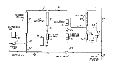
Brief Descri~tion of the Drawinq .
For a better understanding of the invention, reference is
made to the accompanying drawing which illustrates ~:.
diagrammatically a preferred embodiment of the present
invention.
It is a schematic flow sheet showing a typical
hydrocracking process to which the present invention may be ~.
applied.
DescriPtion of the Preferred Embodiments
In the hydrocracking process as shown in the drawing, the
iron salt additive is mixed together with a heavy hydrocarbon
oil feed in a feed tank 10 to form a slurry. This slurry,
including heavy oil recycle 37, is pumped via feed pump 11
through an inlet line 12 into the bottom of an empty tower 13.
Recycled hydrogen and make up hydrogen from line 30 are
simultaneously fed into the tower through line 12. A gas~
liquid mixture is withdrawn from the top of the tower through .
line 14 and introduced into a hot separator 15. In the hot .:~
separator the effluent from tower 13 is separated into a
20 gaseous stream 18 and a liquid stream 16. The liquid stream -~
16 is in the form of heavy oil which is collected at 17. -
The gaseous stream from hot separator 15 is carried by ' :~
way of line 18 into a high pressure-low temperature separator
19. Within this separator the product is separated into a :
gaseous stream rich in hydrogen which is drawn off through
line 22 and an oil product which is drawn off through line 20
and collected at 21.
The hydrogen-rich stream 22 is passed through a packed ;
scrubbing tower 23 where it is scrubbed by means of a .
scrubbing liquid 24 which is recycled through the tower by
means of a pump 25 and recycle loop 26. The scrubbed
hydrogen-rich stream emerges from the scrubber via line 27 and
i9 combined with fresh make up hydrogen added through line 28
and recycled through recycle gas pump 29 and line 30 back to :~
35 tower 13. .
The heavy oil collected at 17 is used to provide the ~ :
heavy oil recycle of the invention and before being recycled
"' .' ~'''
~ 8 2 ~3 ~2 61
back into the slurry feed, a portion is drawn off via line 35 : :
and is fed into fractioner 36 with a heavy oil stream boiling :
above 450~C, preferably above 524~C being drawn off via line
37. This line connects to feed pump 11 to comprise part of :
the slurry feed to reactor vessel 13.
Description of the Preferred Embodiments
Certain preferred embodiments of this invention are :
illustrated in the following non-limiting examples. :
Example 1
The feedstock used was a Cold Lake vacuum tower bottoms
boiling above 446~C. The feedstock had the following
properties:
Table 1 .
ProPerties of the Feedstock :~ .
% C, wt% 83.24 ::
%H, wt% 10.19
%S, wt% 5.58
%N, wt% 0.56
Sum, wt% 99.57
~API 5.1
CCR, wt% 21.1
Distillation,
204-343~C, wt% 0.6
343-524~C, wt~ 24.1
524~C+, wt% 75.3
% PI, wt%
% TI, wt%
% Ash, wt% 0.07
' Fe, ppm 7.4
Ni, ppm 74.2
V, ppm 217.4
PI = Pentane insolubles
TI = Toluene insolubles
CCR = Conradson Carbon Residue
.
9 '~1~126 1 -~ ~
The additive which was used was ferrous sulphate .
monohydrate which had been dry ground using an ACM 10
pulverizer. A micron separator was used after the pulverizer ~
to produce a fine grind additive. A typical assay of the '::
additive is shown in Table 2 below:
Table 2
wt~
Iron 29.000-31.000 ;~
(Average 30
Sulphate 56.5000
Water 12.000
Magnesium 1.2100
Manganese 0.0300
Titanium 0.1400 ~:
Arsenic <0.0001
Lead <0.0001 . ~ ;
Cadmium <0.0001 ~:
Mercury ~0.0001 : .. '
.: ,, .
Chromium 0.0003 :~
Selenium O.0010 ~.,': ,;
Silver 0.0002 .
20. Antimony 0.0030
Zinc 0.0050 - :.
Calcium 0.0030 ~.'
The additive particle distribution, as obtained with a
Hiac 720 instrument was as shown in Table 3 below~
., . .:
': :.,' ;,'
: ,, ,:
lo 2~3126~
Table 3 ~ .
Particle size (~m) Cumulative % below
3 4.6 ~ :
24.5
S 10 65.2
94.2
46 96.9
126 100.0
The above ferrous sulphate monohydrate contained
approximately 25~ of particles having sizes less than 5 ~m and
approximately 65~ of particles having sizes less than 10 ~m.
About 95% of the particles had sizes less than about 20 ~m.
The above feedstock and particulate were used for
carrying out a series of hydrocracking tests with recycle
utili~ing a hydrocracking pilot plant having a capacity of
50 ~ per day.
The pilot plant hydrocracker was heated to 350~C and the
~eed was introduced at this temperature and thereafter the
temperature was gradually increased to an operating
temperature of 447~C. The pilot plant was operated on a
continuous basis at temperatures between 447~ and 453~C, LHSV
~f 0.4 to 0.7 h-1, a pressure of 13.8 MPa and a gas rate of
28 L/min.
~A) Base line runs
A series of base line runs without recycle were first
carried out to obtain the processing characteristics of the
feedstock, the pitch conversion of different conditions and
the~ amount of additive needed for incipient coking temperature
operation.
Each test was run for from l to 10 days and the results ~
obtained are summarized in Table 4 below:
' - 11 2 1 '~ 1 2 6 1 ~
Table 4 :
Temperature HLSV % ICT .
~C h1Conversion Additive, wt~ :
447 0.66 80.6 1.8
447 0.55 86.9 1.9
447 0.42 91.4 2.0 :
447 0.36 94.5 2.0
450 0.70 85.0 2.0
453 0.65 89.3 2.0
(B) Recycle Runs
Using the feedstock and additives described above, a
series of three tests were carried out with recycle. The ~ ~.
pilot plant was operated at a pressure of 13.8 MPa and a
hydrogen gas rate of 28 l/min at a gas purity of 85~
The recycle heavy oil was prepared by fractionating hot ~ .
separator heavy bottoms to cut points between 450~C and 495~C.
The ratio of fresh feed/recycle heavy oil was varied between
80/20 and 89/11, the reactor temperature was varied between
447~ and 453~C and the ~HSV was varied between 0.45 and
0.68 h~
A summary of the recycle conditions is shown in Table 5 : . :
below: .
Table 5
Recycle Fresh Feed/ Recycle Reactor Fresh Feed
Run # Recycle Cut Point Temperature Space
Heavy Oil ~C ~C Velocity
1 86/14 450 447 0.68
2 86/14 495 447 0.65
3 86/14 495 447 0.45' ; .
The results obtained from the above recycle runs are
shown in Table 6 below:
' "~;.'
' :' ',
' '" '.
'~ 12 2131261
Table 6
Recycle Conversion at Additive Additive Additive
Run # Equilibrium Conc. in Conc. in Conc. in
(~) Fresh Feed Recycled Material
(%) Material Entering
(%) Reactor (%)
1 78.3 1.2 4.2 1.6
2 79.4 1.0 5.5 1.6
3 86.7 1.0 3.3 1.3
The above results show a 30-50% reduction in the
requirement of fresh additive particles because of the active ~
particles present in the recycle. :'