Note: Descriptions are shown in the official language in which they were submitted.
WO 93/20764 PCI/US93/03358
2131702
"IMPROVED VENOUS VALVE CUl-rER".
8ACRGROUND OF T~E lNv~ ON
This invention is directed generally to
rendering venous valve leaflets incompetent for
in-situ arterial bypass in patients requiring
arterial reconstruction for chronic limb-
threatening ischemia. More particularly, this
invention is directed to a venous valve cutter
having unique improved cutting surfac~s to
facilitate the incision of the leaflets and a
unigue irrigation system to minimize frictional
forces on the endothelium of the vein when
introducing and withdrawing the cutter.
A common form of chronic limb-threatening
ischemia, femorotibial, obstructive disease,
typically is treated by using the greater
saphenous vein as a bypass conduit.
Traditionally, this vein has been removed from
its anatomic bed and reversed to overcome the
obstruction to flow from its one-way valves.
The distal end of the "reversed flow" greater
saphenous vein is then grafted to the femoral
artery and its proximal end is grafted to the
outflow artery beyond the obstruction.
3Q There are a number of problems inherent in
the use of a reversed flow saphenous vein as a
SUBST~TUTE SHE~T
W093/20764 ' 2 1 3 1 7 ~ 2 PCT/US93/03358
~ . ~
bypass conduit. The narrow distal end of the
~.
vein may not permit enough arterial in-flow from
i~s new parent vessel, whereas the wide proximal
end of the vein makes an anastomosis to the 2-3
~illimeter distal outflow vessel cumbersome.
Also, the body of the vein may twist or compress
and be damaged during the vein removal, reversal
and replacement process and it is difficult to
preserve the very sensitive endGthelial layer of
the vein during the removal and replacement
process. Furthermore, the process may impair
the blood vessel's blood supply (the vasa
vasorum).
Bypass procedures in which a vein is used as
it lies anatomically within the body, without
removal, reversai and replacement, i.e., 'lin-
situ vein bypasses", generally overcome most
problems associated with removing, reversing and
replacing the vein. This is most commonly
accomplished in treating femorotibial disease by
moving a valve cutter through the saphenous vein
to incise the venous valve leaflets.
Since Carrel and Guthrie's publication of the
techniques required for a small vessel
anastomosis, vascular surgeons have attempted
infrainguinal distal revascularizations. The
advantage of the in-situ technique for saphenous
~- vein bypass are first that the narrow end is
S'JBSTITUTE SHEET
W093/207~ ' 2 13 1~ 0 ~ PCT/US93/03358
anastomosed to the smaller artery distally with
the graft tapering in the appropriate direction.
This improves the hemodynamics at both
anastomoses. A second consideration is that the
adventitial blood supply to the vein is
preserved to help protect the endothelial lining
of the vein.
Typically, in performing this procedure
either the distal end of the vein is anastomosed
to the femoral artery to allow arterial blood to
pass into the vein or a s~line solution is
pumped through a cannula into the vein to
provide the required pressure to distend the
-~ ~ vessel and close the valves. These procedures
a~e performed to ensure that the valve cutter
will meet and incise the valve leaflets in their
closed, extended position. Once all of the
- valves are made incompetent, the vein becomes
suitable for use as an arterial bypass conduit.
Unfortunately, it is quite difficult using
currently available valve cutters, to
efficiently and consistently incise and render
the valves incompetent without damaging the
endothelium of the vein or even piercing the
vein wall. The various currently available
valve cutter devices are difficult to
manipulate, often do not center and catch the
,. . .. . .
valve leaves properly, and can cause significant
', '
SUBSTIl IJTE S~E~~T
wo g3/20764 2 1 ~ 1 7 0 2 PCr/USg3/03358
damage to the vein due to intimal contact
between the surfaces of the cutting head and the
vein wall and tearing at the points of valve
attachment to the vessel wall.
U.S. Patent No. 3,837,345, entitled "Venous
Valve Snipper", describes a device for incising
valves in vein grafts to bypass blocked
arteries. This device is not intended to be
used in-situ. The instrument has a closed
position and an open position: it is maneuvered
past the venou~ valves in the direction of blood
flow, opened and withdrawn whereby sharp spikes
spear and impale the venous valve leaflets which
, ~.
are then hopefully incised by closing the device
in a~scissors-like motion.
U.S. Patent No. 4,493,321, entitled "Venous
Valve Cutter for the Incision of Valve Leaflets
:.
~ In-situ", describes a valve cutter in the shape
-~ of a reverse arrowhead for preparing a vein n-
20 situ for an arterial bypass. The valve cutter -~
includes a rounded leader, a cutting blade
enclosed in a protective support, a torsionally
rigid rod connecting the leader to the cutting
blade, and a catheter attached to the cutting
blade support with suture material. The valve
cutter is used by making proximal and distal
incisions in the vein, passing a rod through the
-~ vein, attaching the valve cutter and pulling it
~ SUBSTITUTE SHEET
~'
W093/20764 2 1 ~ 1 7 0 2 PCT~US93/03358
~down the vein while introducing fluid through
the attached catheter to close the valves before
incising them, and then returning the valve
c~utter assembly to the proximal incision. The
orientation of this device must be continuously
controlled to prevent the cutting blade from
catching and tearing the orifice wall of a
contributing venous branch and to ensure
engagement and incision of both leaflets of each
0 ~alve.
U.S. Patent No. 5,047,041, entitled "Surgical
Apparatus for the Excision of Vein Valves In-
situ", describes a valve cutter in which a
circular cut;ing head affixed to a cable is
prec~eA by a dilating segment also affixed to
the cable. The circular cutting edge has series
of rounded guide teeth which are intended to
guide the valve leaflets into cutting grooves
which are supposed to engage and then cut the
valve leaflets. Unfortunately, the rounded
h~rpened guide teeth pull, stretch and likely
irregularly tear the valve leaflets before any
cutting can beyin.
~UMMARY OF THE lNv~lON
Accordingly, this invention is directed to an
improved venous valve cutter for in-situ
incision of valve leaflets which safely,
SUBSTITUTE S~IEET
W093/20764 2'1 '3 i 7 0 2 PCT/US93/03358
efficiently, and consistently renders the venous ''
valves incompetent while minimizing frictional
forces on the endothelium of the vessel and
preventing inadvertent contact between cutting
surfaces and the intima of the vein wall.
~ n important object of this invention is the
provision of a venous valve cutter for ~-situ
incision of valve leaflets which does not pull,
stretch or tear the leaflets' attachments to the
vessel wall.
Another important object of this invention is
the rendering of the venous valves incompetent
for in-situ arterial bypass by cutting blades
which engage and penetrate the valve leaflets
- 15 im~ediately on contact with the cutting head.
A further object of this invention is the
provision of a venou~ valve cutter with
interchangeable cutting heads which enable the
surgeon to appropriately match the head size to
a vessel's tapering lumen.
Yet another object of this invention is the
provision of an integral venous valve cutter
irrigation system which helps center the device
,
while irrigating and opening the valves and
distending the lumen of the vessel to prevent
contact with the vessel wall as the device is
passed up through the vessel in preparation for
the valve cutting procedure.
.
SUBSTITUTE SHE~T
. ~ , .~'. .
CA 02131702 1998-02-20
Stlll another ob~ect of thls lnventlon ls the
provlslon of a valve cutter wlth an lrrlgatlon system ln whlch
fluld ls allowed to pass retrograde lnto the cutter head of
the devlce to flush and lubrlcate lts cuttlng surfaces.
Yet a further ob~ect of the lnvention ls to provide
a venous valve cutter havlng a cuttlng head wlth a cyllndrlcal
portlon whlch helps center the cutter ln the veln.
Yet another ob~ect of the lnventlon ls to provlde a
venous valve cutter havlng a cuttlng head wlth a cyllndrlcal
portion ln whlch channels are provlded to facllltate fluld
passage ln tlghtly flttlng vessels.
In one aspect, the lnventlon resldes ln an
lmprovement ln a venous valve cutter for renderlng venous
valve leaflets lncompetent havlng a cutter head wlth a forward
clrcular cuttlng edge dlsposed ln the dlrectlon of the
lntended movement of the cutter through the veln to render the
valve leaflets lncompetent, the lmprovement comprlslng: a
plurallty of proxlmally dlrected prongs ln the clrcular
cuttlng edge presenting sharp edges, sald prongs havlng flat
leadlng edges and belng separated by slots slmllarly
presentlng sharp edges, sald cuttlng head havlng a contlnuous
cuttlng surface ln multlple planes runnlng along the entlre
forward edge of the cuttlng head.
In another aspect, the lmprovement comprlses means,
attached to sald cutter head, for dlrectlng fluld dlstally to
the cuttlng head.
In a further aspect, the inventlon resldes ln an
lmproved venous valve cutter comprlslng: a cutter head havlng
-- 7
66850-38
CA 02131702 1998-02-20
a forward circular cuttlng edge and means for advancing said
cutter head through a vein to render valve leaflets
lncompetent; said clrcular cuttlng edge havlng a plurallty of
proxlmally dlrected prongs presenting sharp leadlng edges,
said prongs havlng flat leading edges and being separated by
slots similarly presenting sharp cutting edges.
In a still further aspect, the invention resides in
an lmproved venous valve cutter comprising: a cutter head
havlng a forward circular cutting edge and a catheter for
advanclng sald cutter head through a veln to render valve
leaflets lncompetent; sald clrcular cuttlng edge havlng a
plurallty of proximally dlrected prongs presenting sharp
leadlng edges, said prongs being separated by slots similarly
presenting sharp cutting edges; and a leader having a diameter
generally equal to that of sald cutter head and a rigld coll
spring provldlng addltional irrigation sites through spacings
in the spring coils.
In a further aspect, the invention resides ln a
venous valve cutter assembly for renderlng venous valve
leaflets incompetent, including a cutter head and means for
advancing the cutter head, the improvement comprlslng a
plurality of dlfferently slzed lnterchangeable cutter heads
adapted to be removably attached to the advanclng means
whereby cuttlng procedure to match cuttlng head slze to a
vessel's taperlng lumen.
In yet a further aspect, the lnventlon resldes ln a
kit for renderlng venous valve leaflets lncompetent comprlslng
means for advancing the cutter head and a plurallty of
-- 8
66850-38
CA 02131702 1998-02-20
dlfferently slzed lnterchangeable cutter heads adapted to be
removably attached to the advanclng means whereby cuttlng
heads may be changed durlng the valve cuttlng procedure to
match cuttlng head slze to a vessel's taperlng lumen.
BRIEF D~ ON OF THE FIGURES
The features of the present lnventlon whlch are
belleved to be novel are set forth wlth partlcularlty ln the
appended clalms. The lnventlon, together wlth further ob~ects
and advantages thereof, may best be understood by reference to
the followlng descrlptlon taken ln connectlon wlth the
accompanylng drawlngs ln whlch:
FIGURE 1 ls a front plan vlew of a horlzontally
dlsposed, lmproved venous valve cutter ln accordance wlth the
present lnventlon;
FIGURE 2 ls an enlarged vlew of the cutter head and
leader of the valve cutter of FIG. l;
FIGURE 3 ls an enlarged end vlew, ln elevatlon, of
the cutter head of FIG. 1, vlewlng the cutter head from the
pronged end;
FIGURE 3A ls a modlfled enlarged end vlew, ln
elevatlon, of the cutter head of FIG. 1, vlewlng the cutter
head from the pronged end ln whlch channels are provlded to
facllltate fluld passage ln tlghtly flttlng vessels;
- 8a -
66850-38
W093/207~ 2 1 3 1 7 0 2 PCT/USg3/03358
FIGURE 4 is an enlarged elevat.ion view of the
cutter head of FI6, ~, shown in s~ion, taken
along lines 4-4 of ~lG. 3;
FIGURE 4A is a schematic representation of a
interchangeable valve cutter head;
FIGURE 4B is an elevation view of a blunt-
tipped ~esd used to facilitate placement of the
venous valve cutter when interchangeable cutting
heads are to be used;
FIGURES 4C and 4D are elevation views of an
alternative unitary interchangeable valve cutter.
head and leader design and FIGURE 4E is an
~ ~ elevation view of alternate catheter design
.:~ which may~be fitted to the valve cutter head and
: 15 leader of FIGS. 4C and 4D as well as that of
FIG. 9 below;
FIGURE 5 is an enlarged view of the cutter
and leader assembly portion of the device of
FIG. 1, shown in section, taken along lines 5-5
of FIG. 2;
FIGURE 5A is an enlarged view of the cutter
and leader assembly portion of the device of
FIG. 1, shown in section, taken along lines 5-5
o~ FIG. 2 in which optional irrigation ports are
formed in the cutter head and in the cutter
stem.
.
.
,"''~' ' 9
W093/20764 21 31 7 PCT/USg3/033~8
FIGURES 6A-6I comprise a diagrammatic
representation of the operation of the valve
cutter of FIG. l;
FIGURE 7 is a planar representation of the
continuous cutting surface of the present
invention;
FIGURE 8 is an enlarged front plan view,
shown in section, of a cutter head in accordance
with the present invention, in which provision
is made for back flushing the cutter head as the
valve leaflets are excised: and
FIGURE 9 is an enlarged partial view of an
alternative embodiment of the improved venous
valve cutter of the present învention in which a
15 ~fiber optic element is provided for viewing the
vessel and the action of the cutting head in
rendering the valves incompetent, and for
assessing the effectiveness of the cut. ;:
2 0 m;!~CPTPq!ION OF T~E PREFERRED ENBOI)IMENT
An improved venous valve cutter or
valvulotome in accordance with the present
invention is generally designated in FIG. 1 by
the numeral 10. Although the valve cutter is
discussed below in connection with in-situ
bypass procedures, it is not limited to this and
may be applied to any vascular operation
~ requiring a non-reversed vein graft. Such
- ~ 10
~: ~ SUBSTITUTE SHEET
wo g3/20,64 21 ~ 1 7 U 2 PCT/US~3/~3358
applications may, for example, be found duriny
distal infrainguinal bypasses when a non-
anatomic pos~tion is required (ex: profunda
femoris to anterior tibial artery), composite
vein infrainguinal bypasses, or even an aorta-
renal bypass.
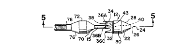
Valve cutter 10 comprises a cutter head 12, a
leader 14, a stem 15 between the cutter head and
the leader, a catheter 16, a handle 18 and a
combination hub and injection port 20.
Cutting head 12 may be~made of any material
which is safe for use in the body and is capable
of taking and holding a knife edge. Stainless
steel is preferred for the f~brication of the
cutting head. The valve cutter may, for
example, include 1.5 mm, 2.4 mm, 3.0 mm, and 4.0
mm or other size diameter cutting heads. The
choice of cutter head size is a matter of
judgement although it is recommended that a size
smaller than the vein be employed.
Turning now to FIGURE 2, an enlarged view of
cutter 12 joined to leader 14 by stem 15 is
shown. The distal end of cutter 1~ is in the
shape of a cone 22 truncated and bored at its
distal tip 24 to provide an irrigation port 26
which communicates with a central lumen 27
(FIGS. 4 and 5). The edge 28 of irrigation port
SUBSTITUTE SHE~T
W093/207~ 213l~ 02 PCT/US93/03358
26 preferably is rounded in order to minimize
the danger of intimal damage.
Immediately proximal to cone 22, the cutter
head surface flows smoothly into a first
cylindrical section 30 which is undercut along
its circumference at 32 to form a second
cylindrical section 34 of slightly lesser outer
diameter than the first cylindrical section.
This undercut further minimizes the danger of
damage to the vein wall as the cutter moves past
the valves.
A plurality of proximally directed prongs 36
are at the proximal or "business end" of
cylindricol section 34. At least two prongs are
required, although four prongs, 36A, 36B, 36C
and 36D axe depicted in the iIlustrated
preferred embodiment, and more can be used. The
prongs are defined by half-oval slots 38 in
cylindrical section 34.
The inside edges of prongs 36A-36D, as
defined by slots 38, are bevelled back to a
margin 40 and ground to present sharp cutting
surfaces 41, as best seen in FIG. 4.
Additionally, the flat leading edges 42 of the
prongs are ground on their inner surfaces at 44
to similarly present sharp cutting edges. Thus,
cutting head 12 is provided with a continuous
cutting surface in multiple planes running along
12
~,
: SUBSTITUTE SHEET
W093/207~ 21~1 ~ O 2 PCT/US93/03358
the entire forward edge 46 of the cutting head,
which is shown in FIGURE 7 as if the wall of the
cutter were laid out in a plane. As a result,
flat leading edge~ 4~ of the prongs pierce the
leaflets whereupon the eight sharp cutting
surfaces 41 continue the shear of the venous
valves as the cutter is pulled through to gently
widen the cut in the valve until the apices 43
of the slots are reached whereupon the entire
valve can be cleanly cored out and captured in
the cutter head at 45 (FIG. 5).
The use of leader 14 is preferred ~ut not
required in the practice of the invention.
Leader 14 is attached to cutter head 12 through
a rigid stem 15, which is centered on the axis
of both the cutter and the leader and forms an
open lumen from irrigation port 26 through the
distal end 50 of the leader, as seen in FIG. 5.
Also, a rigid spring may be used as stem 15 to
20 provide an additional irrigation site through
the spacings between the coils of the spring.
Finally, stem 15 must be of a length sufficient
to permit the valve leaflets to close (clear the
leader) before meeting the leading edges 42 of
prongs 38A-38D.
Leader 14 includes a conical surface 70 which
flows into a cylindrical surface 72 and a then a
trailing conical surface 76. A nipple 78 is
SUBSTITUTE ~;HEET
W093/20764 2 1 3 1 7 0 2 PCT/USg3/03358
provided at the proximal end of the leader for
attachment to catheter 16.
In an alternate embodiment, catheter 16
comprises a tightly wound coil spring covered
with an inextensible sheath. The coil spring is
preferably stainless steel and the sheath i8
preferably a low surface friction
thro~mboresistant material such as polyurethane.
This sheathed coil structure is conformable,
compliant and flexible yet has longitudinal
rigidity for better centering.
Catheter 16 is attached to plastic handle 18
which may be made of polyurethane or other
suitable materials. The~surgeon will gri~ this
l9~ h-~Ale as the device is p~s~e~ through the vein,
and may rotate the cutter head, if desired.
Howevèr! even without physically rotating the
device, the advancing cutting edges of the
prongs produce incisions that advance about the
~ 20 valve leaflets in a circumvolutory fashion.
.~
- The hub/injection port 20 is attached to a
source of saline (not shown). The saline or
other fluid flows from the irrigation port
distçn~ing the vessel's lumen and aiding in the
centering of the device while irrigating and '
opening the valves as the valve cutter is passed
up through the vessel in preparation for the
valve cutting procedure. This minimizes trauma
14
;~ SU~3STITUTE 5HEET
wo g3/20764 2 1 3 1 7 0 2 PCT/US93/03358
to the vessel wall, to preserve a viable,
untraumatized and hence non-thrombogenic
endothelium. In an alternative embodiment,
depicted in FIGURE 5A, irrigation ports 21 could
S be formed in cone 22 or in stem 15 to either
enh~nce the effect of the irrigation from
irrigation port 26 or to replace port 26 which
could be capped off.
The present valve cutter adds a particular
advantage over other such devices if the
proximal anastomosis is no~t performed prior to
rendering the valves incompetent since this
permits the valve cutter to ensure that the
valves are c}osed and thus the valves' maximum
surface area is eYpo~~ for the cutting blade to
engage the valves.
Further, the present valve cutter allows,
- with a small fiber optic bundle inserted through
the irrigation channel in the valve cutter,
direct observation of the incised valves. In an
alternate embo~ir?nt, as illustrated in FIGURE
9, a fiber optic bundle 150 is mounted in the
leader 14 of the valve cutter to enable the
surgeon to view and monitor the action of the
cutting surfaces as they render each successive
valve incompetent.
In yet another embodiment of the invention,
underside irrigation is used in a valve cutter
' ~ ~
:: SUBSTITUTE SH E~T
wo g3/20764 2 1 3 1 7 0 2 PCT/VS93/033~
12A as depicted in FIGURE 8. In this
embodiment, saline or other fluid is p~sce~
through the catheter 100 and into the rearward
section 102 of the cutting head. The saline
accumulates at 102 and is forced out through
ports 104 to flush and lubricate the cutting
edges of the cutting head as they cut into the
valve leaflets.
Turning now to FIGURES 6A-6I, valve cutter 10
is introduced through the proximal end 110 of
vein 112 and heparinized saline 114 is irrigated
through port 26 in the cutting head of the valve
cutter to dilate and lubricate vein 112 before
*he-advancing cutting head which is shown
, ~
passing up through valve 116, comprising
~leaflets 116A and 116B, in FIGURES 6B and 6C.
-~ The pressure gradient established through
~ irrigation port 26 opens the valve leaflets
i ahead of the advancing valve cutter (FIG. 6B)
which then passes through the valve as shown in
FIG. 6C, well lubricated by the saline front
advancing ahead of it.
When the cutting head of the valve cutter has
cleared the valves, its direction is reversed
(FIGURES 6D-6H). The valve cutter is thus
positioned at the most proximal aspect of the
vein and gently the hydrostatic pressure is re-
~,
established to close the nearest proximal valve.
16
SUBSTITUTE SHEET
W093/207~ 21317 02 PCT/US93~033~8
The irrigation pressure gradient should begentle to prevent or minimize hydrostatic
pressure injuries as the valve cutter is gently
advanced, with the vein distended, allowing it
to float proximally. The hydrostatic pres~ure
is maintained so that, with the leaflets closed,
leading edges 42 of the cutting head prongs
engage the leaflets near the vein wall and
immediately pierce them forming a small incision
which is gently widened by the curved cutting
surfaces 41 (FIGURES 6F-6H~ until the valve is
rendered incompetent leaving a clean and
minimally damaged former valve site, as seen in
FIGURE 6I. The irrigation during the proces~ is
provided at a level sufficient to help center
the device while minimizing the danger of
hydrostatic pressure injuries to the vein.
The valve cutter 10 is then positioned at the
most distal aspect of the next valve and gently
the hydrostatic pressure is re established to
- close that valve which is engaged and gently
incised out as described above. Hydrostatic
pressure is maintained and the valve cutter is
pulled down, sequentially engaging and cutting
the next distal valve until all the valves have
~een ren~ered incompetent.
- 0
If the surgeon wishes to construct a proximal
anastomosis prior to using the valve cutter,
SUBSTITUTE SHEET
WO 93/20764 2 1 3 1 7 U 2 Pcr/ US93/03358
thereby allowing the systemic arterial pressure ;
to close the valves, the irrigation port may be
~A~re~ off to prevent loss of blood. However,
the proximal anastomosis does not negate the
S advantage of irrigation during the initial
introduction of the valve cutter at the distal
end of the vein. Also, the surgeon may wish to
pass a fiber optic bundle through the irrigation
channel to view the cutting of the valves as the
valve cutter proceeds down the vein.
In an alternative embodiment of the
invention, as illustrated in FIGURE 3A, channels
llO-llOD are provided in the cylindrical portion
30 of the cutter head to permit fluid flow when
~; 15 the~cutter head encounters a tightly fitting
portion of a vessel thereby preventing
undesirable pressure build up and ensuring
continued lubrication as the cutter passes
through the snugly fitting portion of the
- 20 vessel. -
In yet another alternate embodiment of the
invention, a series of differently sized cutter
heads are provided in a kit with a single valve
:
cutter assembly. This embodiment of the
invention is depicted in FIGURE 4A by a
representative interchangeable cutter head 120
;~ which has an inner female threaded portion 122
: ~ dimensioned to screw onto a corresponding male
~; 18
~ ~ SUBSTITUTE SHEET
W093/207~ 2~13 L7 02 - PCT/US93,033~8
threaded portion 124 at the distal end of stem
126 of the valve cutter assembly. Thus,
differently sized cutter heads with inner
threaded female portions could be substituted
for cutter head 120, along with a blunt-tipped
head to facilitate initial placement of the
device. The blunt-tipped head 130, which is
illustrated in FIGURE 4B, includes a body 132
having a blunt portion 134 and an irrigation
port 134, and an internally threaded portion
135.
An alternative unitary interchangeable cutter
head and leader 136 is illustrated in FIGURE 4C.
It includes a leader 138 with an inner female
thr~ portion 138 dimensioned to screw onto
the co~ o.,~i~g male threaded portion 140 at
the end of catheter 142 (FIGURE 4D)..
Use of the interchangeable valve cutter heads
~- of FIGURES 4A - 4C begins by introducing the
valve cutter assembly fitted with the blunt-
tipped head 130 through the most proximal end of
the vein while heparinized saline is irrigated
through the port to dilate the vein prior to
advancing the device distally. The distal end
of the vein is gently closed with a clamp or
between the fingers of an assistant to allow for
the dilation of the vein. ~With the vein
- ' 19
SUBSTITUTE ~HEET
W093/20764 2 1 3 1 7 0 2 PCT/USg3/033~
dis~en~e~, the valvulotome is gently advanced
allowing it to float distally.
When the catheter reaches the open sapheno-
femoral junction, (or is ~ ~d out through a
distal adequate tributary when the distal
anastamosis is performed prior to the valve
disruption procedure) the blunt tip head is
removed and replaced with an appropriately sized
valve cutter head. The saphenous vein is again
clamped at its open fossa ovalis. The surgeon
must choose a cutting head appropriate for the
size of the patient's greater saphenous vein.
The valve cutter is then positioned at the
most distal aspect of the vein. Fluid is
.;,
. ,
injected through the catheter which distends the
iumen and r~seC back over the cutting head and
closes the valve which is now appropriately
positioned for cutting. The fluid is injected
to present a dilated vessel for the floatation
of the device and a functionally closed valve
for the cutting head to engage.
The valve cutter is withdrawn thus engaging
and cutting the most distal valve. Slow and
consistent traction is all that is required.
The hydrostatic pressure is maintained and the
n ' valve cutter assembly is pulled down engaging
and cutting each sequential valve, until all
~ valves have been rendered incompetent within the
,:
~ 9 20
~ ~ o~ SUBSTITUTE SHEET
.. ;, . . . .
, ~ ~
wo g3/20764 2 1 3 1 7 0 ~ PCT/US93/03358
~ppropriate range relative to the chosen cutting
head. Judgment of the surgeon best determines
when the catheter i~ again passed back through
the unclamped distal sapheno-femoral junction
where the cutting head is replaced with a larger
head.
The procedure is repeated and again judgment
determines the appropriately sized cutting head
for the vessel's lumen~ The appropriately sized
valve cutting head will best cut the valves at a
given position in the vessel. Preferred cutting
head sizes include 1.5mm, 2.4mm, 3.0mm and
4.0mm. The choice of the particular size is a
matter of judgement although it is recommended
that a size smaller than the vein be employed.
The ability to change cutting heads in this
catheter allows the surgeon to appropriately
match the heads to the vessel's tapering lumen.
Finally, c~rrent devices fitted with fiber
optic elements at best permit the surgeon to
view the valve distally and do not permi~ the
cutting edge to be viewed as it penetrates the
valve because the vessel collapses as the cutter
penetrates through the valves. As illustrated
in Figure 9, in the present device the valve can
be visualized proximately so that the cu~ting
edge can be observed as it penetrates without
the vessel collapsing. In this manner, each and
SUBSTITUT~ SHE~T
W093/207~ 8 ' PCT/~S93/03358
~ ' 21~17~)2
p every valve can be observed by the surgeon as
~; the cutter edge penetrates.
O Thus, FIG. 9 illustrates an enlarged partial
view of an alternative embodiment of the
5 improved venous valve cutter of the present
inve~tion in which a fiber optic element is
provided~for viewing the vessel, the action of
the cutting head in rendering the valves
incompetent, and for assessing the effectiveness
10 of the cut. In this embodiment, the cutting end
.-~ 150 of the cutter head is_fixed to a leader 152
in which a fiber optic element 154 is mounted.
This unique fiber optic mounting permits the
- surgeon to observe th~ cut*ing edge of the
~,
cutter head as it penetrates each valve using
conventional apparatus (not shown).
It should be understood that various changes
and modifications to the preferred embodiments
described herein will be apparent to those
20 skilled in the art. Such changes and -
modifications can be made without departing from
the spirit and scope of the present invention
and without diminishing its attendant
advantages. It is therefore, intended that such
changes and modifications be covered by the
following claims.
~ '
. 22
~: '
SUBSTITUTE SH EET
; .