Note: Descriptions are shown in the official language in which they were submitted.
WO 94/12785 -1- PCT/GB93/02472
A HEAT ENGINE AND HEAT PUMP
This invention relates to heat engines and heat
pumps, and in particular to those for providing power
and/or heat appropriate to domestic appliances, service
industries, commerce and manufacturing industry.
The attainment of high thermal efficiency is nearly
always an important consideration in the field of power
generation for the reason that the fuel cost is generally
responsible for about two thirds of the cost of the power
produced. In addition to the cost incentive, enviromental
considerations require that greater effort be directed
towards the achievement of higher efficiencies in order to
minimise the production of carbon dioxide and other
undesirable emissions.
In general it is possible to achieve a higher thermal
efficiency and fewer emissions in large generating units
than in small ones. This is partly because of heat losses,
friction and leakage flows which tend to be proportionally
less significant in large units than in small ones. Also
economies of scale make it possible to have more
sophisticated equipment in large units. In small units,
the cost of such equipment may be prohibitive.
In spite of these factors, there are circumstances
where small generating units are needed and it is important
that they should be as efficient and enviromentally benign
as possible. This situation arises in the many parts of
the world where no electricity grid is available. It may
WO 94/12785 - 2 - PCT/GB93/02472
be that construction of a power station to supply
electricity is beyond the financial capacity of the local
population or it may be that the electricity demand is too
small to justify its construction. The former situation
arises in many less developed countries. The latter
situation applies in many remote or thinly populated
regions and on offshore islands.
Another application for small efficient engines
arises in connection with combined heat and power (CHP).
The use of heat and power together usually results in a
higher overall energy efficiency than the use of mains
power from the electricity grid. Since heat cannot be
transported economically over any significant distance, CHP
systems have to be sized for the local heat load. This
usually implies generating units of modest size.
The invention described here can be applied either as
a heat engine or in modified form as a heat pump. Heat
pumps transfer heat from a low temperature heat source to a
high temperature heat sink. For example, in cold weather a
heat pump can extract heat from the atmospheric air and
pump it to a higher temperature in order to heat a
building. Alternatively, in~hot weather, the heat pump can
operate as an air conditioning unit to extract heat from
the internal air of the building and reject it to the
outside atmosphere, even though the outside temperature is
higher than the inside temperature. The heat pump may also
be used to cool air in order to condense the water vapour
in it. The heat rejected from the heat pump may then be
used to restore heat to the air. In this case the heat
pump is used to de-humidify the air. As with CHP, heat
pumps have to be sized in accordance with the local heat
load. Consequently, most heat pump capacity will be
required in the form of small rather than large units.
Most types of heat pump, air conditioning unit or
refrigeration system require the use of an
WO 94/12785 - 3 - PCT/GB93/02472
evaporating/ condensing fluid which boils aL an appropriate
temperature such as one of the chloro-fluoro-carbons
(CFC's). These substances are known to deplete the earth's
ozone layer which protects human and animal life from
harmful ultra-violet radiation. Although certain
alternatives to CFC's are known, some of these also cause
ozone depletion, but to a lesser degree. Other
alternatives have disadvantages such as flammability,
toxicity, high cost, poor thermodynamic properties or a
tendency to increase global warming.
Engines and heat pumps based on the Stirling Cycle
are well known. One form of Stirling engine includes a
compression chamber and an expansion chamber connected
together via a regenerative heat exchanger forming a gas
space which contains a working gas. According to the ideal
Stirling Cycle working gas in the compression chamber is
compressed by a piston and undergoes isothermal
compression, the heat of compression being rejected to a
low temperature heat sink. After this process is complete
the cold working gas is pushed through the regenerator
where it is preheated before entering the expansion
chamber. In the expansion chamber, the hot compressed
working gas is allowed to expand by forcing the piston out
of the expansion chamber. During expansion, heat is added
to the working gas so that the gas expands isothermally.
The hot expanded gas is then pushed back through the
regenerator to which it gives up its heat before being
admitted to the compression chamber to begin the next cycle.
US 4148195 describes a heat actuated heat pump which
requires a high temperature heat source such as the
combustion of fuel and another heat source at low
temperature such as atmospheric air. The heat output is at
an intermediate temperature. The purpose of the heat pump
is to convert a certain amount of heat energy at high
temperature to a larger amount of heat energy at the
intermediate temperature. This is done by extracting heat
. . ,:
WO 94/12785 - ~ - PCT/GB93/02472
energy from the low temperature heat source. The heat
actuated pump described in US 418195 is a closed-cycle
system without valves which approximates to the Stirling
cycle. Liquid pistons contained in a series of four
interconnected U-tubes and which are ccnnected in a closed
circuit displace the working gas between adjacent expansion
and compression chambers formed in the arms of the
U-tubes. The liquid pistons transmit power around the
closed circuit directly from the expanding gas in the
expansion chamber to the compressing gas in the adjacent
compression chamber, an expansion chamber and a compression
chamber being formed in opposed arms of the same U-tube.
The four U-tubes are connected via the gas space with
regenerators. T-ao of the four regenerators and the
associated gas volumes work in a temperature range between
the high temperature and the intermediate temperature. The
other two regenerators and associated gas volumes work in a
temperature range between the low temperature and the
intermediate temperature. The cycle is operated in such a
way that power is transmitted via the medium of the liquid
pistons from the gas volumes working over the high
temperature range to the gas volumes working over the low
temperature range.
21st Inter-society Energy Conversion Engineering
Conference Volume 1 (1986) pages 377 to 382 describes a
Stirling heat actuated heat pump similar to that described
in US4148195, in which the working gas is heated or cooled
by taking liquid from a liquid piston, heating or cooling
the liquid externally and reinjecting it into the expansion
or compression cylinder as an aerosol.
One drawback of these known heat pumps is that the
maximum working temperature of the high temperature heat
source is very low in comparison to what can be achieved in ,
- 2~.~~~5~
WO 94/12785 - 5 - PCT/GB93/02472
modern advanced power generating technologies, such as the
combined cycle gas Turbine. For example the temperature of
heat addition to the heat pump is likely to be limited to
400°C, whereas the ~urbine inlet temperature of a modern
power generating gas turbine is anything up to 1300°C.
Consequently the efficiency of conversion of the high
temperature heat to internal work within the heat actuated
heat pump is also low, as would be expected from
considerations of Carnot's theorem. As a result the
overall coefficient of performance is very low.
Another disadvantage of the heat ac~uated heat pump
described in US 4148195 lies in the fact that the liquid
pistons have to be very long in order to achieve a low
natural frequency of oscillation. The frequency of
oscillation must be low because sufficient time must be
allowed for heat transfer~between the droplet spray and the
gas. The required length of liquid piston is particularly
difficult to achieve in a small device operating at high
pressure. Also friction losses arising from long liquid
pistons are likely to become unnacceptably high in a small
device. Furthermore a high value for the ratio of length
to stroke is required to avoid the so-called shuttle loss
which arises from the transfer of heat from one end of each
liquid piston to the other end. The shuttle loss occurs
because the two ends of each liquid piston are at different
temperatures and there is consequently some mixing of the
liquid and transport of heat.
US 3608311 describes an engine whose operation is
based on the Carnot Cycle, in which gas is successively
compressed and expanded in a single cylinder by a liquid
displaces. Hot and cold liquid from the liquid displaces
is alternately injected into the cylinder to heat the gas
during part of the expansion process, and to cool the gas
CA 02150359 2004-05-12
' -6-
during part of the compression process.
One drawback of this known heat engine is that the
power output per cycle is relatively low because it
requires an extremely high compression ratio to raise the
temperature of the working gas to a reasonable value during
adiabatic compression, and such a compression ratio is not
possible in practice. A further drawback of this engine is
that the working gas is continually cycled between high and
low temperatures while remaining in the same cylinder
throughout the process. Therefore the walls of the cylinder
also cycle from low to high temperatures and back again
which implies large entropy changes and a reduction in
thermodynamic efficiency.
According to one aspect of the present invention
there is provided a heat engine comprising a compression
chamber to contain gas to be compressed and a first piston
to compress said gas by movement of the piston in said
compression chamber and driving means arranged to drive
said. first piston into the compression chamber to compress
said gas, an expansion chamber and a second piston to allow
gas to expand therein by movement of the second piston out
of the expansion chamber, means to feed compressed gas from
said compression chamber to said expansion chamber, and
heating means arranged to heat said compressed gas from the
compression chamber, transmission means comprising a solid
member operatively coupled to said second piston to permit
power from the engine to be drawn, means to form a spray of
liquid in said compression chamber to cool the gas on
compression therein, and separator means arranged to
separate liquid from the compressed gas leaving said
compression chamber.
One advantage of this arrangement is that heat is
rejected efficiently to the liquid in the liquid spray, at
the lowest temperatures in the heat engine cycle.
Furthermore, expansion is done in a separate chamber so
that temperatures in each chamber and therefore the various
parts of the chamber and of the pistons do not cycle
between high and low temperatures, and thus reducing the
WO 94/12785 - 7 - PCT/GB93/02472
efficiency.
In a preferred embodiment, the engine further
comprises means to add heat to the gas in the expansion
chamber during expansion thereof. Thus, the expansion
process may be approximately isothermal.
Preferably, the heating means also includes heat
exchanger means arranged to pre-heat compressed gas from
the compression chamber with heat from gas expanded in the
expansion chamber. Thus, expanding the gas isothermally in
the expansion chamber provides an opportunity of recovering
some of this heat in a heat exchanger which is used to
pre-heat the compressed gas from the compression chamber
prior to expansion. The heat exchanger may for example be
a regenerative heat exchanger if expanded gas from the
expansion chamber flows along the same flow path as the
incoming compressed gas from the compression chamber, or a
recuperative heat exchanger if the gases flow along
different flow paths. A recuperative heat exchanger is
particularly advantageous where heat exchange is required
between two gases where mixing of the gases is undesirable
and/or the two gases are at' substantially different
pressures.
One embodiment includes means for returning expanded
gas leaving the expansion chamber to the compression
chamber for recompression. The returning means may be
separate from the means for feeding compressed gas to the
expansion chamber, or the working gas may flow back and
forth between the compression and expansion chambers along
the same flow path. Embodiments in which the same body of
working gas is continuously recycled between the
compression and expansion chambers will be referred to as a
closed-cycle engine. Because the working gas is sealed
within the engine, the gas can be pre-pressurised so that
the minimum pressure attained by the gas during the cycle
is much greater than atmospheric.
.. . s ~ . I , . y
WO 94/12785 - 8 - PCT/GB93/02472
In one embodiment of the engine, the means to add
heat to the gas in the expansion chamber comprises means
forming a spray of hot liquid in the expansion chamber.
The liquid used in the spray may be :zeated using an
external heat exchanger and the source of heat may be waste
heat e.g., industrial waste heat, solar energy or heat from
a combustion chamber cooling system. Using a hot liquid
spray to transfer heat into the expansion chamber is
particularly advantageous when used in closed-cycle engines
which have a heat source at relatively low temperature.
Liquid sprays are not suitable for use at very high
temperatures.
An alternative embodiment includes first valve means
operative to admit air or other oxidising gas into the
compression chamber, second valve means operative to
prevent gas in the expansion chamber returning to the
compression chamber through said means for feeding
compressed gas to the expansion chamber and wherein the
means to add heat comprises means to provide a combustible
fuel in the expansion chamber. In this embodiment, the
mixture of fuel and hot compressed gas in the expansion
chamber ignites and after expansion the combustion products
are expelled from the engine via the heat exchanger means .
A fresh supply of working gas is therefore required at the
beginning of each cycle. Embodiments in which the working
gas is renewed each cycle will be referred to as an
open-cycle engine. One form of this embodiment may include
means to control the rate of flow of combustible fuel into
the expansion chamber to provide substantially isothermal
expansion.
It is generally preferable that the first and second
pistons provide a good seal for the working gas and this is
particularly important in the closed-cycle engine.
Advantageously, the first and/or second pistons may
comprise a liquid thus eliminating the sealing difficulties
' 2~.~~~~ ~
WO 94/12785 - g - PCT/GB93/02472
:~hich may otherwise be present if the pistons are solid. A
preferred embodiment comprises a pair of generally U-shaped
conduits each containing a body of liquid as a piston, a
compression chamber formed in each arm of one conduit and
an expansion chamber formed in each arm of the other
conduit, and means feeding compressed gas from one of said
compression chambers to one of said expansion chambers and
separate means feeding compressed gas from the other
compression chamber to the other expansion chamber. In
this embodiment, expansion and compression each occur twice
per cycle and the timing of the liquid pistons is
preferably arranged so that the expansion process in one of
the expansion chambers drives the compression process in
one of the compression chambers. This may be achieved by
appropriate coupling between the drive means and the
transmission means. A preferred embodiment comprises
another pair of said generally U-shaped conduits whereby in
use, the liquid piston in one U-shaped conduit containing
expansion chambers is substantially 90° out of phase with
the liquid piston in the corresponding U-shaped conduit
containing the other expansion chambers. It will thus be
appreciated that this arrangement can provide a net
positive power output at each stage during a complete cycle
of the engine, thereby removing the need for a fly wheel or
other means to sustain the operation of the engine between
power strokes.
When expanded gas is forced out of the expansion
chamber by movement of the second piston into the expansion
chamber, the gas pressure is increasing. A preferred
embodiment of the engine includes means to provide liquids
of at least two different temperatures for use in the
liquid spray in the expansion chamber and includes means
forming a spray of liquid during compression of gas in the
expansion chamber to control the gas temperature. The
temperature of the liquid spray is preferably such that the
temperature of the gas remains constant during compression
thereof. Advantageously, if said second piston comprises a
.
' 5 O ~ 5 ~ _ 1 ~ _ PCT/GB93/02472
z
liquid, said means to provide may be arranged to supply
liquid from the liauid piston directly to the spray forming
means.
After compression of gas in the compression chamber,
the gas pressure decreases and the gas expands as a result
of both pistons moving out of their respective chambers. A
preferred embodiment includes means to provide liquids of
at least two different temperatures in the liquid spray in
the compression chamber and includes means forming a spray
of liquid during expansion of gas in the compression
chamber to control gas temperature. Preferably, the
temperature of the liquid spray is such that the gas
temperature is maintained constant during expansion.
Advantageously, if said first piston comprises a liquid,
said means to provide may be arranged to supply liquid from
said first piston directly to the spray forming means.
Where any of the first pistons comprise a liquid, the
drive means may comprise a member arranged to cooperate
with the first piston such that motion of the member
imparts motion in at least one direction to the piston.
The member may comprise a solid piston and may be immersed
in the liquid piston or floating on the surface thereof.
The solid piston may be coupled to a shaft extending
through the wall of the conduit containing the liquid
piston.
Likewise, where the or one of the second pistons
comprises liquid, the transmission means may comprise a
member arranged to cooperate with said second piston such
that motion of the liquid piston in at least one direction
is imparted thereto. The member may comprise a solid
piston which is immersed in the liquid piston or arranged
to float on the surface thereof. A shaft may be coupled to
the solid piston and extend through the wall of the conduit
containing the second piston.
e~
WO 94/12785 - 11 - PCT/GB93/02472
Alternatively, the first and second piston gay
comprise a solid material. One embodiment includes a pair
of compression chambers and a pair of expansion chambers
wherein in use the pistons in the compression chambers are
arranged to move substantially in antiphase with each other
and the pistons in the expansion chambers are arranged to
move substantially in antiphase with each other. In a
preferred embodiment, another said pair of compression
chambers and another said pair of expansion chambers are
provided wherein in use, the pistons in one pair of
compression chambers are arranged to move substantially
90° out of phase with the pistons in said other pair of
compression chambers and the pistons in one pair of
expansion chambers are arranged to move substantially 90°
out of phase with the pistons in the other said pair of
expansion chambers.
Preferably, in a closed-cycle engine the heat
exchanger means comprises a regenerator. The purpose of
the regenerator is to enable heat to be transferred to and
from the working gas efficiently.
In a preferred embodiment, separator means are
provided to separate liquid from the gas leaving the or
each compression chamber. In embodiments operating in a
closed-cycle, a separator means may also be provided to
separate liquid from the gas leaving the or each expansion
chamber.
Where the first and/or second pistons comprise a
liquid, means are preferably provided to supply the or each
means forming a spray with liquid from the liquid pistons.
Advantageously, said means to supply may include a pump
arranged to be driven by a respective piston.
In one embodiment said driving means includes
coupling means coupled to said transmission means so that
..
WO 94/12785 ' ~ - ~ 12 - PCT/GB93/02472
in use, said first and second pistons move in predetermined
phase relationship. It will be appreciated that coupling
the first and second pistons together by for example a
:mechanical means such as a crankshaft is a convenient
method to enable large compression ratios to be achieved,
and at the same time maintain the phasing of the pistons.
The phase angle between the first and second pistons may be
such that the second piston leads the first piston by at
least 90° Alternatively the pistons could be driven
independently and may each be adapted together with any
means for coupling to an external drive, to withstand
substantial forces against the pressures in their
respective chambers.
In one embodiment, the engine may further comprise a
combustion chamber for the combustion of fuel, wherein the
heating means comprises means to heat compressed gas from
said compression chamber with heat conducted across at
least one of the surfaces defining the combustion chamber
of the engine. Thus, advantageously the present invention
may readily be adapted to provide a cooling apparatus for a
conventional combustion engine (e. g. petrol, diesel or gas)
which recovers heat, normally wasted by conventional
cooling apparatus and converts this heat into useful
power. Cold compressed gas is produced in the compression
chamber and heat lost to the combustion chamber walls is
transferred to the compressed gas to provide cooling of the
engine. The same method can be used to recover heat from
the exhaust gases of a conventional combustion engine, for
example by putting compressed air cooling channels through
the exhaust manifold or by including a heat exchanger
through which the exhaust gases would pass. The pre-heated
compressed gas is then injected into the expansion chamber .
which expands forcing the piston out of the chamber and
thereby generating useful mechanical work. In one
embodiment, the expansion piston may be connected to an
external output drive of the engine. This arrangement has
the advantage of
WO 94/12785 ' - 13 ~ ~ ~ ~ ~ ~ PCT/GB93/02472
increasing the efficiency of conventional combustion
engines.
According to another aspect of the present invention
there is provided a heat pump comprising an expansion
chamber to contain gas to be expanded and a first piston to
allow the gas to expand by movement of the piston out of
the expansion chamber, a compression chamber to contain gas
to be compressed and a second piston to compress said gas
by movement of said second piston in the compression
chamber, means to feed gas from one of said expansion
chamber and said compression chamber to the other chamber,
and means to form a spray of liquid in said compression
chamber to absorb heat from said gas during compression,
wherein said second piston is adapted to be driven by an
external source of power into said compression chamber to
compress the gas.
This form of heat pump enables the pumped heat to be
transferred to an external heat sink extremely efficiently
via the medium of a liquid spray in the hot compression
chamber and at the same time can be driven through, for
example a mechanical coupling, by an external source of
power and in particular an electric motor to provide a heat
pump with a higher coefficient of performance than can be
achieved by known heat pumps.
Advantageously, this form of heat pump can perform
heating or cooling in either a closed-cycle or an
open-cycle. For example, one embodiment may be adapted for
air conditioning in which air is drawn into the compression
chamber from an external source, compressed substantially
isothermally using the liquid spray and passed to the
expansion chamber in which it expands, so that it does
work, returning some of the energy used for compression.
The expansion may be adiabatic so that the gas cools, and
the cool gas may then be ejected from the heat pump to
provide air conditioning. Alternatively, another
embodiment of the heat pump may further include means to
WO 94/12785 - 14 - PCT/GB93/02472
supply heat to the gas during expansion thereof in the
expansion chamber so that the expansion is approximately
isothermal. This may be done efficiently by employing a
liquid spray in the expansion chamber. Heat is absorbed
from the liquid droplets, which cool, and the cooled spray
liquid may be used for cooling, e.g., air conditioning.
The liquid spray injection into the expansion chamber also
allows efficient heat transfer from a low temperature heat
source so that the heat pump can pump this heat to higher
temperature sink, for the purpose of heating. The heat
pump can be modified for either open or closed-cycles.
In another embodiment the heat pump may further
comprise heat exchanger means arranged to pre-heat said
expanded gas with heat from compressed gas leaving the
compression chamber. This is particularly advantageous in
the closed cycle in which the same gas is pumped back and
forth between the expansion and compression chambers.
A preferred embodiment includes coupling means for
coupling the second piston to the external source of power,
wherein the coupling means is adapted to withstand
substantial force against the pressure of gas in the
compression chamber. Coupling the heat pump to an external
source of power in this way, enables much higher pressures
and therefore a higher compression ratio to be achieved in
the compression chamber so that a greater amount of heat
can be pumped per cycle than achieved by prior art heat
pumps. At the same time, the use of such a coupling
enables the heat pump to be compact, since the attainment
of high pressures (and therefore output) does not rely on
the inertia of the pistons which would have to be
relatively massive and therefore large in size. The ,
coupling means may for example comprise a crank shaft.
In a preferred embodiment, the first and second
pistons are coupled together by a mechanical coupling
means, e.g. a crank shaft so that the phasing of the
, . ',
WO 94/12785 - 15 - PCT/GB93/02472
pis~ons can be easily controlled.
Another important advantage of the heat pump
according to the present invention is that it does not
require an evaporating or condensing fluid, and can be used
with a gas which does not condense and a liquid which does
not evaporate to any significant degree. There is no
requirement for a specific boiling point. Indeed, it is
possible to choose a gas such as helium and a liquid such
as water, which will cause no harm to the environment
should they be released. This is also an important
advantage of the heat pump according to the present
invention. An additional advantage of not requiring a
specific boiling point is that the heat pump can work over
a wider range of operating temperatures than conventional
heat pumps.
The heat pump may include any one or more of the
preferred or alternative features mentioned above in
association with the heat engine.
Embodiments of the heat engine and heat pump may
include any number of compression and expansion chambers
and the number of compression and expansion chambers need
not be equal.
Examples of embodiments of the present invention will
now be described with reference to the drawings in which:-
Figure 1 shows a schematic diagram of a first
embodiment of the present invention which includes liquid
pistons and operates in a closed-cycle:
Figure 2 shows a schematic diagram of a second
embodiment of the present invention including liquid
pistons and which operates in an open-cycle,
Figure 3 shows a schematic diagram of a third
WO 94/12785 - 16 - PCT/GB93/02472
embodiment of the present invention including solid pistons
and which operates in an open-cycle, and
Figure 4 shows a schematic diagram of a fourth
embodiment of the present invention including solid pistons
and which operates in an open cycle.
Referring to Figure 1, a pair of U-shaped conduits 1
and 3 each contain a body of liquid 5 and 7. A compression
chamber 9, 11 is formed in each of the arms 13 and 15 of
one of the U-shaped conduits 1 and an expansion chamber 17,
19 is formed in each arm 21 and 23 of the other U-shaped
conduit 3. One of the compression chambers 9 is connected
through a regenerator 25 to one of the expansion chambers
19 and the other compression chamber 11 is connected
through another regenerator 27 to the other expansion
chamber 17. In practice; the U-shaped conduits shown in
Figure 1 would each be rotated 90° to face each other,
with the regenerators having the same length. The two
U-shaped conduits and regenerators are thus configured as a
saddle and will be referred to as "saddle loop". An engine
or a heat pump which consists of a single inter-connected
mass of gas with a single regenerator, a single compression
chamber and a single expansion chamber, each with a liquid
or solid piston and each with means for addition or removal
of heat is described as a "half saddle loop".
Liquid sprays are provided in both compression
chambers and both expansion chambers. Liquid used in the
sprays 29 and 31 in the compression chambers is preferably
drawn from the body of liquid in the conduit 1 and the
liquid sprays 33 and 35 in the expansion chambers 17 and 19
is preferably drawn from the liquid in the corresponding _
conduit 3. The liquid drawn from conduit 1 may be passed
through a cooler (not shown) prior to injection in the ,
compression chambers 9 and 11 and liquid drawn from conduit
3 may be passed through a heater prior to inj ection in the
expansion chambers 17 and 19. A working gas fills the
WO 94112785 - 17 - PCT/GB93/02472
space formed by the compression chambers 9 and 11 and their
corresponding expansion chambers 19 and 17 with which they
communicate via a respective regenerator 25 and 27.
Separators 37, 39, 41 and 43 are provided between the
chambers and corresponding regenerators to remove any
liquid in the working gas before the fluid passes through
the regenerator concerned.
Each U-shaped conduit 1 and 3 has a linear section 45
and 47 joining the adjacent arms. Mechanical means coupled
to each liquid piston is provided to transmit power to and
from the pistons. In this embodiment, a solid piston 49
and 51 is disposed in each of the linear sections of the
conduit and is free to execute linear motion along the
length thereof with the liquid pistons formed either side.
A drive shaft 53, 55 is connected to each solid piston 49
and 51 and extends through the wall of each conduit to
provide means for driving or transmitting power from the
liquid pistons.
The two drive shafts 53 and 55 are coupled together
by an external drive mechanism so that the displacement of
each piston is approximately sinusoidal with time and so
that a predetermined phase relationship is maintained
between the pistons in different conduits. This can be
achieved for example by coupling the drive shafts 53 and 55
to a crankshaft as for petrol or diesel engines.
The engine operates by passing the working gas
through a thermodynamic cycle which involves repeated
compressions and expansions. The compression is done when
most of the working gas is in the compression chamber 9 and
11 while the expansion is done when most of the working gas
is in the expansion chamber 17 and 19. This may be
achieved by arranging for the pistons in the expansion
chambers to lead the pistons in the compression chambers by
a phase angle of 90° The phase angle between the pistons
in the expansion chambers or compression chambers
- . _ '
WO 94/12785 - 18 - PCT/GB93/02472
is 180° With this arrangement, the expansion process in
one of the expansion chambers will drive the compression
process in the other compression chamber. For example
expansion in chamber 19 will drive the compression in
chamber 11 and the expansion in chamber 17 will drive the
compression in chamber 9.
One complete cycle of the engine will now be
described in relation to one compression chamber and one
expansion chamber only, beginning with compression in
compression chamber 9. At the start of compression the
liquid piston in the compression chamber 9 is at the bottom
of its stroke and the piston in the expansion chamber 19 is
at the mid-point of its stroke and moving upwards. Most of
the working gas shared between the compression chamber 9
and the expansion chamber 19 is in the compression chamber
9. The compression pistcn moves into the compression
chamber 9 and compresses the working gas against the gas
pressure resulting from movement of the expansion piston
into the expansion chamber 19. Cold liquid is sprayed into
the compression chamber to cool the working gas during
compression. This liquid may be obtained by drawing off
liquid from the cold liquid piston (i.e. the compression
piston) and then passing it through an external cooler (not
shown) before injecting it into the compression chamber.
When the compression piston in compression chamber 9 is at
the mid-point of its stroke the expansion piston in
expansion chamber 19 will be at the top of its stroke and
about to reverse direction. As the compression piston
continues moving upwards in the compression chamber,
compression of the working gas continues but at the same
time the cool compressed gas begins to flow through the
regenerator towards the expansion chamber 19 as the
expansion piston begins to move downwards. The cool
compressed gas leaving the compression chamber 9 is
pre-heated with heat from the expanded gas which left the
expansion chamber at the end of the previous cycle.
_ 2.~~~~~~
WO 94/12785 - 1 s - PCT/GB93102472
when the compression piston in compression chamber 9
has reached the top of its stroke, the expansion piston in
expansion chamber 19 is at the mid-point of its stroke and
moving downward, out of the expansion chamber. Hot, liquid
is sprayed into the expansion chamber to maintain the
temperature of the gas as it expands on continued downward
movement of the expansion piston. This liquid may be
obtained by drawing off liquid from the hot liquid piston
(i.e. the expansion piston) and then passing it through an
external heater (not shown) before injecting it into the
expansion chamber. At the same time, the compression
piston has reversed direction and is moving out of the
compression chamber 9. To prevent the gas in the
compression chamber from cooling during expansion it may be
advantageous to spray liquid drawn directly from the liquid
piston rather than liquid which has been pre-cooled in an
external cooler.
When the expansion piston has reached the bottom of
its stroke in the expansion chamber 19 the compression
piston will be at the mid-point of its stroke in the
compression chamber 9 and moving downwards. The expansion
piston reverses direction and the two pistons move in
opposite directions forcing the working gas out of the
expansion chamber, through the regenerator and into the
compression chamber. The hot expanded gas leaving the
expansion chamber is pre-cooled in the regenerator before
returning to the compression chamber. As the expansion
piston moves upwards into the expansion chamber, the gas
remaining in that chamber undergoes some compression. To
prevent heating of the gas, liquid may be sprayed into the
exapnsion chamber. This liquid should preferably be taken
directly from the hot liquid piston without passing through
the external heater. When the compression piston in the
compression chamber 9 reaches the bottom of its stroke, the
expansion piston in the expansion chamber 19 is at the
mid-point of its stroke and travelling upwards into the
expansion chamber, the compression piston reverses
- _.~
WO 94/12785 ' ~ ~ 2 0 - PCT/GB93/02472 i
direction and the cycle is repeated.
As mentioned above, the thermodynamic cycle in
chambers 9 and 19 is 180° out of phase with the cycle in
chambers 11 and 17. Thus, the expansion stroke in chamber
19 drives the compression stroke in chamber 11 and the
expansion stroke in chamber 17 drives the compression
stroke in chamber 9. However, there are points in the
cycle between the compression and expansion strokes where
no net power output from the engine is occuring. Thus, to
sustain the operation of the engine over the cycle a fly
wheel may be used or it may be possible to rely on the
inertia of the pistons themselves if they are massive
enough. However, the need for a fly wheel can be avoided
by providing a second saddle loop whose operating cycle is
arranged to be 90° out of phase with that of the first
saddle loop. This may ~be achieved by incorporating an
appropriate external drive mechanism. This embodiment of
the heat engine is then capable of providing a net energy
output at all stages of the cycle.
One of the most important features of the engine
described above is the use of hot and cold liquid sprays to
maintain the temperature of the working gas within each
chamber at the desired value. As stated above, the liquid
sprays may be maintained throughout the cycle, although the
liquid passes through the heat exchangers during only part
of the injection cycle. The reason for this can be
explained in connection with each chamber separately.
During compression, the function of the spray is to
keep the working gas temperature in the compression chamber
as low as possible. Thus the liquid should be passed
through the external cooler during this part of the cycle.
When the gas is expanded, in a later part of the cycle, the ,
function of the spray is to prevent the gas from cooling
too much. During this part of the cycle, it is better to
take the liquid directly from the liquid piston and not to
WO 94/12785 - 21 - PCTlGB93/02472
cool it.
The converse argument applies to the expansion
chamber. During expansion the gas must be as hot as
possible and therefore the liquid spray should be passed
through the external heater. During compression, it is
important to prevent the gas from becoming too hot.
Therefore, the liquid should be taken directly from the
liquid piston during this stage.
In one embodiment, the pumping of the liquid used for
the spray may be achieved by making direct use of the
reciprocating motion of the piston and drive shaft. The
pump which may be mounted within the conduit comprises a
small piston driven by the liquid piston, the solid piston
or the drive shaft and which is arranged to slide in a
cylinder incorporating non-return valves. A single pump in
each conduit may be provided if the pump is double ended
i.e. fills and pumps at both ends. This enables liquid to
be supplied from each end alternately while the other end
is filling. One double ended pump would serve two liquid
spray injectors associated with that particular conduit.
Each end of the pump may have two outlets, one which leads
to the spray nozzle in one of the chambers associated with
the particular conduit, while the other leads directly to
the spray nozzle in the other chamber. Thus, although a
liquid spray would be maintained almost continuously, the
temperature of the injected liquid would vary during the
cycle according to whether it had passed through the heat
exchanger or not.
The separators situated above the spray injector
nozzles and which may comprise corrugated plates, also play
an important part in the heat transfer process between the
liquid spray and working gas, since the corrugated surfaces
are expected to be cooled or heated by contact with the
liquid from the spray, and will extend the contact area
between the working gas and the liquid. When the gas flow
~~.5~ ~5 9
WO 94/12785 - 2 2 - PCT/GB93/02472
in a particular chamber is upward, then most of the
droplets injected at that time will be carried upwards into
the separator. However there will still be many droplets
in the lower gas space, resulting from the injection at
earlier times. When the gas flow is downward, most of the
liquid that has been separated onto the corrugated plates
will be swept downwards into the chamber. In this way, it
is expected that the separators will repeatedly collect
then discard the liquid carried over into them. The
separators may in addition, or alternatively be arranged to
cause the working gas to swirl to facilitate the removal of
liquid droplets, while at the same time minimising the
pressure loss of the gas flow.
The purpose of the regenerators is to change the
temperature of the working gas from hot to cold or vice
versa in a thermodynamically efficient way. The
regenerator may comprise an array of narrow channels of
various cross sectional geometries designed to provide a
large heat transfer area between the gas and the material
of the regenerator. The narrow channels may be formed
using for example plates or tubes. The regenerator stores
the heat from the working gas until the working gas
reverses its direction of flow, after which the heat is
restored to the working gas. The regenerator should also
be designed to minimise the pressure drop over its length.
The choice of working gas and heat transfer liquid in
the liquid pistons depends on the application and the
temperature range over which the engine needs to work.
Because the engine operates in a closed-cycle and the
liquid pistons form a perfect seal, the choice of working
gas is not necessarily restricted by availability or cost
and may be chosen for its thermodynamic properties. Thus,
the working gas may be for example helium or hydrogen,
which have excellent heat transfer characteristics. Helium
may be preferred to hydrogen on safety grounds, although it
would be more expensive. Another advantage of the
2~~0~5~
WO 94/12785 - 2 3 - PCT/GB93/02472
closed-cycle engine is that the operating pressures of the
working gas can be relatively high and would generally be
in the range of 1-20 MPa (10-200 bar).
At operating temperatures up to about 200°C, water
may be used as the heat transfer liquid. However, at
higher temperatures water would probably not be suitable
because of the high pressures needed to maintain it in the
liquid state. For operating temperatures up to about
400°C, commercial heat transfer fluids which are also
liquid at low temperatures may be used. It is likely that
helium would again be selected as the working gas for this
higher temperature range. For operating temperatures above
400°C a liquid metal such as the sodium-potassium eutectic
mixture (NaK) may be used with helium as the working gas.
Eutectic NaK remains liquid down to -12°C and boils at
785°C (at atmospheric 'pressure). Molten salts are
possible high temperature alternatives to liquid metals.
However, because of the likely engineering difficulties in
designing an engine suitable for use with high temperature
liquids at temperatures above 400°C, it may be better not
to use a hot liquid at all. Instead, heat may be
transferred into the engine through the walls of a heat
exchanger enabling the engine to be driven from much higher
temperature heat sources including the combustion of fuel.
This fuel could be heavy oil, coal, biomass or domestic
waste, since the products of combustion do not enter the
engine. Thus, embodiments of the heat engine which employ
hot liquid injection, are very suitable for power
generation from relatively low temperature heat sources
such as industrial waste heat or solar energy.
The closed-cycle heat engine can be modified to
operate as a heat pump in which mechanical energy is used
to pump heat from a low temperature source to a high
temperature sink. Thus, in contrast to the heat engine,
compression is done on the working gas when the gas is hot
and expansion is done when the working gas is cold. One
embodiment of the heat pump may be described with reference
2 ( ,5 0 3 5 q 2 4 PCT/GB93/02472
~o Figure 1. ~~In this embodiment, mechanical energy to
drive the heat pump~-'is imparted to the solid pistons 49 and
51 via drive shafts 53 and 55. In contrast to the heat
engine, the liquid piston in the compression chamber leads
the piston in the associated expansion chamber by a
predetermined phase angle, e.g. 90° instead of vice
versa. Referring to Figure 1, liquid sprays 29 and 31 in
chambers 9 and 11 are used to transfer heat to the heat
pump from a low temperature heat source. Cool liquid is
injected into chambers 9 and 11 during expansion of the
working gas in the chambers which is driven by the liquid
pistons. During expansion, heat from the spray is
transferred to the working gas and the expansion process
may be approximately isothermal. After heat has been
extracted from the droplets in the liquid spray, the now
cooler droplets recombine with the liquid in the liquid
piston whose temperature 'will decrease as a result. Cool
liquid from the liquid piston is passed to a suitable heat
exchanger (not shown) in which heat is transferred to the
liquid from a. heat source. The heat source for the cold
liquid could be atmospheric air, the ground, a river,
stream or other body of water. Another possibility is to
use extracted stale air from a ventilation system as the
heat source. Alternatively warm waste water from baths
etc. may be used. This is the converse of the operation of
the heat exchanger in the heat engine in which the heat
exchanger transfers heat from the liquid to a low
temperature heat sink.
Liquid sprays 33 and 35 in chambers 17 and 19 spray
hot liquid into the chambers during compression of the
working gas which is driven by the liquid piston. The hot
liquid spray serves as a heat sink to the working gas,
absorbing the heat produced by the work of compression.
After compression, the now hotter liquid droplets in the
spray recombine with the liquid piston whose temperature is
thereby increased. Hot liquid from the liquid piston is
passed to a suitable heat exchanger (not shown) in which
WO 94/12785 - 2 5 - PCTlOB93/02472
heat from the liquid is transferred to the point of use.
This is the converse of the operation of the heat exchanger
in the heat engine in which the heat exchanger transfers
heat from a hot source to the liquid. The heat may, for
example be supplied to a hot water system similar to those
used in many households. Alternatively the heat may be
supplied to a ducted air system.
A cycle of the heat pump in relation to one of the
cold chambers 9 and the associated hot chamber 19 proceeds
as follows, beginning with the liquid piston in the hot
chamber 19 at the top of its stroke and reversing direction.
As the liquid piston reaches the top of its stroke in
the hot chamber 19, the liquid piston in the cold chamber 9
is reaching the mid-point of its stroke and moving out of
the cold chamber 9. On 'continued movement of the liquid
piston out of chamber 9, the cool gas expands and at the
same time, cool liquid is injected into the cold chamber
via the spray 29. The working gas in chamber 9 absorbs
heat from the liquid spray and the gas expands
approximately isothermally. When the liquid piston in cold
chamber 9 reaches the bottom of its stroke and reverses
direction, the liquid piston in hot chamber 19 reaches the
mid-point of its stroke and is moving out of the chamber.
As the liquid piston in chamber 9 moves into the chamber,
cool working gas is forced out of the chamber, passes
through the regenerator in which it is preheated with heat
from the working gas which left the hot chamber at the end
of the previous cycle, and enters the hot chamber 19. When
the liquid piston in chamber 19 reaches the bottom of its
stroke and reverses direction, hot liquid is sprayed into
chamber 19 via spray nozzle 35. At this point the liquid
piston in chamber 9 reaches the mid-point of its stroke and
most of the working gas is in the hot chamber 19. The
liquid piston in chamber 19 moves upwards into the chamber
and compresses the working gas. The heat of compression is
transferred to the liquid droplets in the hot spray and the
2~~~33~~~
WO 94/12785 - 2 6 - PCT/GB93/02472
compression process ,rnay be approximately isothermal. As
the liquid piston in chamber 19 reaches the mid-point of
its stroke, the liquid piston in the cold chamber 9 reaches
the top of its stroke and reverses direction. On continued
movement of the liquid piston into chamber 19 the working
gas is forced out of the chamber and through the
regenerator 25 to which it gives up its heat. The cool gas
leaving the regenerator returns to the cold chamber where
the cycle begins again.
When the piston in the cold chamber 9 is moving into
the chamber and forcing gas out, the gas pressure
increases, tending to increase the gas temperature. Liquid
may be sprayed into the cold chamber as the gas is being
compressed to prevent the gas from heating too much and
preferably to maintain the gas temperature constant. If a
liquid piston is used, liquid for the spray may
advantageously be drawn directly from the liquid piston.
Similarly, when the piston in the hot chamber is moving out
of the chamber and drawing gas in, the gas pressure drops,
tending to lower the gas temperature. To prevent this,
liquid may be sprayed into the hot chamber as the gas
expands, so as to maintain the 'gas temperature constant.
If a liquid piston is used, liquid for the spray may
advantageously be drawn directly from the liquid piston.
As for the heat engine, two saddle loops may be used
and these will be 90° out of phase with each other.
Preferably, the working gas is a gas which does not pass
through a phase transition (i.e. condense or evaporate)
within the range of operating temperatures and pressures
used in the heat pump. The working gas may, for example,
be helium or hydrogen as for the heat engine. The heat
transfer liquid may be water, and depending on the
temperature of the cold source, anti-freeze may have to be
added. If air is used as the heat source, then the heat
source heat exchanger may have to be regularly de-frosted.
WO 94/12785 - 2 7 - PCT/GB93/02472
The heat pump may be used for example for domestic or
commercial applications for air-conditioning,
refrigeration, space heating or for heating water. The
efficiency of a heat pump is usually expressed as the
co-efficient of performance, or COP, which is the
conversion ratio of electricity to heat. The COP also
depends on the temperatures of the heat source and the
required heat supply. For heating of water for space
heating and other domestic purposes, a conventional heat
pump might be able to achieve a COP of about 3. The heat
pump cycle described above, is expected to achieve COP's of
about 3.5 in a domestic application when the heat source is
just above freezing temperatures. The achievable COP
should be about 4 with the heat source temperatures
increased by the use of solar panels or by heat recovery
from domestic waste water. Alternatively a heat pump as
described above could extract heat from the atmosphere at
near freezing point to provide ducted warm air for space
heating at a COP of about 4. The COP could be improved
above 4 if some heat was recovered from waste water, from
stale ventilation air or from solar warming.
Returning to the heat engine, another embodiment
relies on the combustion of fuel to add heat to the working
gas. A combustible fuel is injected into the expansion
chamber, mixes with the hot compressed gas and ignites.
The fuel is preferably a clean fuel such as gas or light
distillate oil. An embodiment of this version of the heat
engine is shown schematically in Figure 2. Many of the
features in the embodiment shown in Figure 2 are similar to
those of the embodiment shown in Figure 1 and like features
are represented by like numerals.
Referring to Figure 2, the heat engine comprises a
pair of U-shaped conduits 1 and 3 each partially filled
with liquid each of which serves as a liquid piston.
Compression chambers 9 and 11 are formed in the arms 13 and
15 of one of the conduits 1 and combustion chambers 17 and
...
WO 94/12785 - 2 8 - PCT/GB93/02472
19 are formed in the arms 21 and 23 of the other conduit
3. One of the compression chambers 11 is arranged to
communicate with one of the combustion chambers 17 through
a heat exchanger which is.:preferably a regenerator 27 and
the other compressiom.c~iamber 9 is arranged to communicate
with the other combustion chamber 19 through another heat
exchanger 25 which may also be a regenerator. The
compression chambers 9 and 11 are provided with gas inlet
valves, to admit air or other oxidising gas into the
chambers and these may, for example be non-return valves.
Each compression chamber 9 and 11 has a liquid spray
injector 29 and 31, the liquid used in the spray being
drawn from the liquid piston, as before. Another valve 61,
63 is positioned between the compression chamber 9, 11 and
the regenerator 25, 27 to prevent exhaust gases from the
combustion chamber 19, 17 via the regenerator 25, 27
returning to the compression chamber 9, 11. An exhaust
port 65, 67 operated by an exhaust valve 69, 71, is
provided between valve 61, 63 and the regenerator 25, 27 to
enable exhaust gases to be expelled after passing through
and giving up their heat to the regenerator 25, 27. A fuel
inlet port 73, 75 is provided in each combustion chamber
17, 19 to enable fuel to be introduced into the chamber.
Each exhaust valve 69 , 71 is operated by a suitable timing
mechanism (not shown).
The engine cycle in relation to one of the
compression chambers and the associated combustion chamber
is as follows. When the level of liquid in the compression
chamber 9 falls to the point at which the internal pressure
becomes less than the pressure on the other side of the
non-return valve 57, the inlet valve 57 opens and oxidising
gas is drawn in. If the gas source is atmospheric air,
then the inlet valve will open when the pressure in the
compression chamber is less than atmospheric. As the
piston in the compression chamber reaches and falls beyond
the mid-point of its stroke, the piston in the combustion
chamber 19 reaches the bottom of its stroke and reverses
WO 94/12785 - 2 g - PCT/GB93/02472
direction. The exhaust valve 65 is cpened and as the
combustion piston moves into the combustion chamber, the
exhaust gases are forced through the regenerator giving up
their heat in the process. The non-return valve 61
prevents the exhaust gases from entering the compression
chamber 9.
When the combustion piston reaches and goes beyond
the mid-point of its stroke in the combustion chamber, the
compression piston reaches the bottom of its stroke and
reverses direction. When the compression piston reaches
its lower limit and starts to move upwards, the inlet valve
closes so that the oxidising gas that was drawn in becomes
compressed. The liquid spray maintains the gas close to
ambient temperature, thus providing an approximately
isothermal compression. During compression when the
compression piston is between its lower limit and the
mid-point of its stroke, the expansion piston continues to
move into the expansion chamber 19 forcing the hot
combustion gases through the exhaust port 65 via the
regenerator 25. When the pressure in the compression
chamber exceeds that of the combustion chamber, the
non-return valve 61 connecting the chambers opens and cool
compressed gas passes through the regenerator, extracting
heat so that it enters the combustion chamber at high
temperature. The combustion piston reverses direction and
moves out of the combustion chamber while the compression
piston approaches the top of its stroke in the compression
chamber. Shortly before the liquid piston reaches the top
of its stroke in the compression chamber, and shortly
before the combustion piston in the combustion chamber
reaches the mid-point of its stroke, fuel is injected into
the combustion chamber 19 and ignites either spontaneously
or with the help of a pilot flame or spark (not shown). At
some point during the continued downward movement of the
combustion piston out of the combustion chamber, the fuel
is turned off. The rate of injection of fuel may be
regulated to provide approximately isothermal expansion.
WO 94/12785 - 3 0 - PCT/GB93102472
'='he compression piston will have reversed direction drawing
a fresh supply of gas into the chamber and as the
combustion piston approaches the bottom of its stroke the
exhaust valve 65 opens and the cycle is repeated.
To avoid the need for.a fly wheel, two saddle loops
:gay be provided which are -~a'rranged to operate 90° out of
phase from each other. A mechanical drive system would be
used as for the closed-cycle engine. The liquid forming
the liquid piston in the conduits containing the combustion
chambers and the compression chambers may be oil, water or
possibly another fluid. The liquids in the two conduits
are not necessarily the same. Floats 22, 24 comprising a
solid material which float on the surface of the liquid
piston in each combustion chamber may be provided to limit
the contact of the combustion gases with the liquid. Some
means of cooling the combustion chamber walls may also be
provided.
Both the closed-cycle engine and the open-cycle
engine described above produce a work output involving
large reciprocating forces at low frequency, for example
about 1 Hz. If the engines are' to be used in electrical
power generation, a means would generally have to be
provided to convert the slow speed form of mechanical
energy into a suitable form to drive an electric
generator. For modest unit sizes with a generating
capacity up to about 1 MW, a slow speed crank shaft could
be used, connected to a generator by appropriate gearing.
Alternatively, a hypo-cyclic gear mechanism or worm drive
gearing may be used. In the case of hypo-cyclic gears, the
drive shaft of the engine is connected to a planet wheel
having gear teeth around its external circumference. The
planet wheel rolls around the inside of a fixed wheel
having gear teeth on its internal circumference. The
planet wheel is mounted on an arm which rotates as the
planet wheel rolls around the inside of the fixed wheel.
The rotating arm drives a generator via a speed-up
4 ~~ :. ~ ' ~
w WO 94/12785 - 31 - PCT/GB93/02472
gearing. This achieves the same kind of motion as a
crankshaft, but with the advantage that large side thrusts
otherwise produced by a crankshaft, are avoided. It is
also possible to make the hypo-cyclic gear more compact
than a conventional crankshaft. Alternatively, the engine
could be adapted to pump a hydraulic fluid through a
turbine connected to a generator. This technique would be
suitable for both large and small unit sizes.
In another embodiment the liquid pistons may be
replaced by solid pistons. Although it is possible to use
solid pistons in the closed-cycle engine in which the
working gas is passed back and forth between the expansion
and compression chambers, it may be difficult to achieve
adequate sealing of the enclosed high pressure gas, which
is likely to be helium or hydrogen. Sealing is less
critical for the open cycle engine in which a fresh supply
of air or other oxidising gas is used at every cycle and
consequently the use of solid pistons might be more
appropriate for this case. Figure 3 shows one embodiment
of this form of heat engine.
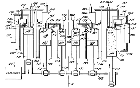
Referring to Figure 3, an embodiment of the engine is
generally indicated at 100, and comprises four cylinders
113, 115, 121 and 123. A piston is provided for each
cylinder and each piston is connected to a crankshaft 169
by a connecting rod 171. In this embodiment, the engine is
oriented such that the crankshaft is above the cylinders.
Compression chambers 109 and 111 are formed in two of the
cylinders 113 and 115 and expansion chambers 117 and 119
are formed in the other cylinders 121 and 123. Each
compression chamber has a gas inlet port 156, 158
controlled by gas inlet valves 157, 159 and a compressed
gas outlet port 173, 175. A gas feed line 177, 179
connects a compression chamber 109, 111 with a respective
expansion chamber 119, 117 via a compressed gas inlet port
181, 183, each controlled by a gas inlet valve 185, 187 in
the expansion chamber 119, 117. Each expansion chamber
~~.~~359
WO 94/12785 - 3 2 - PCT/GB93102472
117, 119 has an exhaust gas outlet port 167, 165 controlled
by an exhaust valve 193, 191. All the gas inlet and outlet
ports are situated near the bottcm of the expansion and
compression chambers.
A spray nozzle 129, 1311 is provided in each
compression chamber 109, 111 for injecting a liquid spray
into each chamber 109, 111 during compression. A separator
137, 139 is mounted within each compression chamber 109,
111 to remove liquid from the compressed gas before the gas
leaves the compression chamber. Thus the separator 137,
139 is situated above the compressed gas outlet port 173,
175. Various kinds of separator may be used, but it is
important for the separator to be as compact as possible
without causing too great a pressure drop in the gas
entering the chamber or the compressed gas leaving the
chamber. To avoid the separator causing a pressure drop in
the flow of inlet gas, the gas inlet port may be situated
on the piston side of the separator. To achieve small
pressure loss, the separator may comprise a number of small
swirl vanes mounted in short pipe sections with the pipe
sections mounted in parallel. The induced swirl of gas
causes entrained droplets to ~be thrown outwards and
collected at the pipe walls. Swirl vane separators are
often used for example in the steam generators and steam to
steam reheaters of pressurised water reactors.
Each separator 137, 139 is connected to an external
cooler 197, 199 by a duct 201, 203. The flow of liquid
from the separator to the cooler is controlled by valves
205 and 207, which may be non-return valves. Cooled liquid
from the cooler is returned to a compression chamber via a
duct 209, 211 and a valve 129, 131 which may be of the .
non-return type. The flow of liquid around this circuit
may be driven by the cyclic pressure variation in the
compression chamber, which forces the liquid through the
non-return valves in the required direction. It is
necessary to maintain a gas space above the liquid level
. ,
WO 94112785 - 3 3 - PCT/GB93/02472
within the cooler to allow this process to occur. This
could be done by the use of a level controller, such as a
ball valve, mounted in the cooler. A separate supply of
liquid may be connected to the cooler to replace any liquid
which is lost in the gas flow to the combustion chamber.
The replacement of liquid may also be controlled by the
level controller, if this is used.
The separator and cooling circuit described above
provides for the separation, re-circulation and pumping of
cooled liquid as a fine spray into the compression chamber
without the use of external pumps. A similar arrangement
may also be implemented in heat engines having liquid
pistons. For some applications it may be appropriate not
to use a non-return valve upstream of the spray injector,
but to control the injection using for example, a cam which
would allow better control of the timing of the spray.
Preferably, the tiaing is optimised to take account of the
pressure difference between the cooler and the compression
chamber and the finite transit time of the droplets within
the chamber. Alternatively, internal or external pumps may
be used to drive the flow of liquid through the spray
injectors. In this case the pumps are preferably
mechanically coupled to the piston shafts so that a
separate power source is not needed. Spray pumps are more
likely to be appropriate for use with engines or heat pumps
in which there is a liquid piston, because of the slower
operating speed. In these cases, the transit time of the
droplets may be rather short in comparison with the time to
complete one cycle of the engine.
Each expansion chamber 119, 117 has a regenerative
heat exchanger 125, 127 mounted so that gas passes through
the heat exchanger before entering or leaving the expansion
chamber via the inlet and outlet ports respectively. Each
expansion chamber has a fuel injection valve 174, 176
controlled by a suitable timing mechanism and a spark plug
178 to ignite the fuel/gas mixture which may be used for
starting the engine or for both starting and continuously
~~.~~3~9
WO 94/12785 ~ , . . . ~ : , ~ - 3 4 - PCT/GB93/02472,
during running.
The regenerative heat exchanger gay consist of a
large number of parallel channels of small diameter and
short length cast for example in a honeycomb structure.
The heat exchanger is mounted inside the combustion chamber
in order to simplify the design and minimise the unswept
gas volumes, but a separate regenerator might be preferred
for some applications.
The chambers are arranged in pairs, each pair
comprising one compression chamber feeding cool compressed
gas to one expansion chamber. The operating cycle of the
pairs of chambers are separated by 180° In this
embodiment, this is accomplished by an appropriate design
of crankshaft 169. In each pair the expansion process in
the expansion chamber leads the compression process in the
compression chamber by a predetermined phase angle which in
this particular embodiment is 90° Again, the phase angle
is fixed by appropriate design of the crankshaft 169. In
this way, compression takes place when most of the gas is
in the compression chamber, and expansion takes place when
most of the gas is in the expansion chamber. Also, the
expansion process occurring in the expansion chamber of one
pair of chambers directly drives the compression process
occurring in the compression chamber of the other pair.
The operating cycle of one pair of chambers proceeds
as follows, beginning with gas induction into the
compression chamber. As the compression piston reaches the
bottom of its stroke in the compression chamber, (i.e.
farthest point from the crankshaft 169) the gas inlet port
157 opens and gas is drawn into the compression chamber as
the piston moves out of the compression chamber 109. At
the same time, the compressed gas inlet port 181 in the
expansion chamber is closed and fuel is injected into the
expansion chamber 119 as the expansion piston reaches
WO 94!12785 - 3 5 - PCT/GB93/02472
mid-stroke moving out of the expansion chamber. The
mixture of fuel and gas in the expansion chamber ignites
and the combustion gases expand driving the expansion
piston to the top of its stroke, (i.e. nearest point
relative to crankshaft 169).
The expansion piston reverses direction and the
exhaust valve 193 opens and the exhaust gases pass through
the regenerator 125 and are expelled through the exhaust
port 189. Gas continues to be drawn into the compression
chamber until the compression piston reaches the top of its
stroke when the gas inlet valve 157 closes. The
compression piston reverses direction and moves into the
compression chamber at which point cool liquid is sprayed
into the chamber cooling the gas during compression.
As the compression' piston reaches mid stroke, the
expansion piston reaches the bottom of its stroke in the
expansion chamber and reverses direction. At this point
the exhaust valve 191 closes and the compressed gas inlet
valve 185 opens, allowing cool compressed gas from the
compression chamber to flow into the expansion chamber.
The compressed gas passes through the regenerator 125 in
which it is pre-heated with heat from the exhaust gases.
As the compression piston in the compression chamber
reaches the bottom of its stroke, the compressed gas inlet
valve 181 in the expansion chamber 119 closes and fuel is
injected into the expansion chamber, mixes with the
pre-heated compressed gas and ignites. The combustion gas
expands forcing the expansion piston to the top of its
stroke and the cycle is repeated. Liquid removed from the
compressed gas before leaving the compression chamber is
forced out of the compression chamber through valve 205.
The liquid is cooled in the cooler 197 before being
returned and injected into the compression chamber.
The other pair of chambers progress through a similar
2~~0~~~
WO 94112785 . - ; 6 - PCT/GB93/02472
cycle but as mentioned above the operating cycles of each
pair are separated by 180° Such an engine could run
satisfactorily if the motion was sustained throughout the
cycle with a large fly wheel. However, the engine may
comprise two sets of four cylinders connected to a single
crankshaft, with the operation of each set of four
cylinders being out of phase by 90° This would allow
positive drive at all stages of the cycle, with the result
that a fly wheel would not be necessary to achieve
continuous operation.
In addition, it may also be possible to design an
engine comprising one compression chamber and one expansion
chamber as long as some means are provided to sustain the
operation of the engine over the cycle period between the
expansion or combustion strokes.
The orientation of an engine with solid pistons may
be as shown in Figure 3, with the crankshaft above the
cylinders. This has the advantage that the separation and
removal of liquid droplets from the cylinder is assisted by
gravity. On the other hand it may not be so easy to
provide lubrication to the crankshaft and there may be
other practical disadvantages to this arrangement. An
alternative arrangement is to place the crankshaft below
the cylinders and to arrange the piston to push the spent
spray liquid out through the valve leading to the expansion
cylinder. Means of separating the liquid could then be
provided in the pipe leading to the expansion chamber. An
alternative method of separation for the configuration with
the crankshaft below the cylinders is for the piston to
push the liquid over an internal weir at the top of the
cylinder. The liquid would then be drained away by
gravity. This would avoid the need for a large connecting
pipe and external separator.
The attraction of using solid pistons instead of
liquid pistons is that it should be possible to run the
WO 94/12785
- 3 7 - ~ '~ PCTIGB93/02472
engine at higher speeds. This implies a higher output for
a given unit size, such that this engine could be suitable
for mobile applications, for example in boats and road
vehicles, in addition to static power generation. The
sealing of the pistons will in general not be as good as
that if liquid pistons were used, but the sealing in an
open-cycle engine is not as important as it is in a
closed-cycle engine. It is also possible to devise an
engine comprising both liquid and solid pistons, for
example with liquid pistons in the compression chambers and
solid pistons in the combustion chambers.
Figure 4 shows another embodiment of a heat engine
which is similar to that shown in Figure 3 but which has
been modified in a number of ways for improved performance
including better efficiency and a much higher output in
terms of work rate.
The heat engine shown in Figure 4 comprises a pair of
compression cylinders 113, 115 each having associated spray
liquid cooling and re-circulating apparatus, and a pair of
expansion or combustion cylinders 121, 123 and the
description of these components described above in relation
to the embodiment shown in Figure 3 applies to
corresponding components shown in Figure 4 and like
components are designated by like reference numerals. The
modifications to the heat engine which contribute to the
improved performance of the embodiment shown in Figure 4,
will now be described.
The moisture separators 137 and 139 have been removed
from the interior of the compression chambers 109 and 111
and instead placed externally of the compression chambers
and are connected in the compressed air feed lines 177, 179
between the compressed gas outlet port 173, 175 of the
compression chambers and the hot compressed gas inlet ports
165, 167 of the expansion chambers 119 and 117. Placing
the moisture separators outside the compression chambers
WO 94/12785 - 3 8 - PCT/GB93/02472
removes the dead volume within the chambers which would
otherwise be present throughout compression and contribute
to a lower compression ratio. Compressed gas outlet valves
204 and 206 have been added to seal the compression
chambers 109 and 111 from the volume enclosed by the
external pipework leading from the compressed gas outlet
ports 173, 175 of the compression chambers to the inlet
ports of the expansion chambers, and' to control the final
pressure of the compressed gas in each compression chamber
before the gas is passed to a respective expansion chamber
and also to control the timing of the flow of compressed
gas to the expansion chambers. Both the addition of the
outlet valves 204 and 206 and the removal of the moisture
separators from the inside of the compression chambers
enables much higher compression ratios to be achieved.
The regenerative heat exchangers 125 and 127 which
are housed within the expansion chambers in the embodiment
shown in Figure 3, have been replaced by recuperative heat
exchangers 244 and 246 mounted externally of the expansion
chambers in the embodiment shown in Figure 4. Again, this
greatly reduces the dead volume within the expansion
chambers so that the energy of expansion of the hot
compressed gas admitted into the expansion chambers is not
wasted by firstly expanding into the dead volume of exhaust
gas, from the previous cycle, trapped within the
regenerative heat exchangers, and thereby reducing the
temperature of the gas. Thus, much higher temperatures can
be achieved in the expansion chamber.
The recuperative heat exchangers 244 and 246 are each
connected in a respective compressed gas feedline 177, 179
between a respective moisture separator 137, 139 and the
hot compressed gas inlet port 181, 183 of a respective
expansion chamber and are arranged to pre-heat the cool
compressed gas from the compression chambers with exhaust
gas leaving the expansion chambers through the exhaust
ports 165, 167. The increased compression ratio obtainable
WO 94/12785 - 3 9 - PCT/GB93/02472
from the engine shown in Figure 4 means that the ratio of
the absolute temperatures before and after expansion is
increased also. The temperature after the expansion is
likely to be similar for both the engines shown in Figure 3
and Figure 4 since this is determined by the materials of
the heat exchanger. Hence the peak temperature of the
engine shown in Figure 4 will be higher and the average
temperature of heat addition during the expansion will be
higher also. The above mentioned improvements enable both
higher pressure differences and high temperatures to be
achieved within the cycle, with heat being rejected at the
lowest temperature within the cycle and heat being added at
the highest temperature, which leads to an increase in
power output.
Further modifications have been made the embodiment
shown in Figure 4 to recover waste or excess heat in
various parts of the cycle and to convert this heat into
useful power, to increase the efficiency of the engine. In
particular, each of the combustion cylinders 123, 121 is
surrounded by a cooling jacket 212, 214 for recovering heat
conducted through the combustion chamber walls. A bypass
line 208, 210 is connected into the compressed gas feedline
177, 179 between the moisture separator 137, 139 and the
recuperative heat exchanger 244, 246 to supply cool
compressed air from the compression chamber 109, 111 to the
cooling jacket 212, 214. The bypass line 208, 210 is
connected near the bottom on the cooling jacket 212, 214
where the temperature of the combustion chamber walls is
least. A pair of expansion cylinders 220, 222 are provided
with associated pistons 224, 226 which are also connected
to the crank shaft 169 via connecting rods 171. Each
expansion chamber has a gas inlet port 216, 218 controlled
by an inlet valve 232, 234 and a gas outlet port 236, 238
controlled by an outlet valve 240, 242. The inlet port
216, 218 is connected to a point near the top of the
cooling jacket 212, 214, the uppermost part of which
surrounds the exhaust port and extends to the hot side of
WO 94112785 - 4 0 - PCT/GB93/02472
the recuperative heat exchanger 244, 246, where ~he
temperatures are expected to be greatest.
Thus, heat lost to the walls at,.the top ,of the
combustion chamber is recovered and converted into useful
work by directing part of the cool compressed gas from the
compression chambers to the combustion chamber walls.
Compressed air is much more effective as a cooling medium
than air at atmospheric pressure. The cool compressed air
enters the cooling jacket near the bottom in order to first
cool the combustion chamber walls since the combustion
chamber walls have to be kept below a temperature which is
determined by the lubricating oil. The compressed gas is
pushed upwards in the cooling jacket towards the top of the
combustion chamber, absorbing heat and gradually rising in
temperature. Having gained some heat in this cooling
process, the compressed air is then used to cool the hotter
parts of the system, such as the cylinder head and valves.
Finally, the hot compressed air is intermittently extracted
from the cooling system by opening the inlet valve into the
expansion chamber in which it expands, driving the
associated piston out of the chamber, thereby generating
additional mechanical work.
Because, in practice, the heat capacity of the
exhaust gas leaving the combustion chambers will generally
be larger than the compressed gas from the compression
chambers, there will be more heat available in the exhaust
gas titan is required to pre-heat the cool compressed gas in
the recuperative heat exchangers. This excess heat may
also be recovered by compressing more gas than is required
for combustion, directing this gas through the recuperative
heat exchangers in which it is pre-heated with the excess
heat available in the exhaust gas and then directing this
pre-heated compressed gas to one or more of the expansion
chambers.
The advantage of this modification is a reduction in
WO 94/12785
- 41 - PCT/GB93/02472
the final temperature of the exhuast gases, and an increase
in the fuel efficiency of the engine.
One or more expansion chambers to recover waste or
excess heat from various parts of the engine may also be
used in any of the other embodiments described herein.
The embodiment of the heat engine shown in Figure 4
is essentially symmetrical about the vertical centre line A
with the right hand half of the engine being a mirror image
of the left hand half. In this particular embodiment, the
three pistons to the left of the centre line A are 180°
out of phase from the three pistons to the right of the
centre line, since this is expected to give the most
uniform torque on the crank shaft 169. Also, the
combustion chamber pistons in each half of the engine are
arranged, via the crank shaft, to lead the corresponding
compression chamber pistons by about 90° This will
provide a high torque to the crank shaft at the time when
it is needed to achieve a high pressure in the compression
chamber. This arrangement also has the possible advantage
that compressed air is drawn into the combustion chamber
from the feed line and heat exchanger before this gas is
replenished by the opening of the outlet valve from the
compression chamber.
A complete operating cycle of the heat engine shown
in Figure 4 will now be described with reference to the
three cylinders to the left of the centre line only, as the
operation of the right hand side of the engine is
essentially the same but is 180° out of phase. In this
example, air is used as the oxidising gas for combustion,
although this need not necessarily be the case.
When the piston 112 in the compression chamber 109
reaches the top of its stroke and begins to reverse
direction, the compressed gas outlet valve 204 closes and
the inlet valve 157 opens and atmospheric air is drawn into
WO 94/12785 - 4 2 - PCT/GB93/02472
the compression c:~amber through' the air inlet port 156. ~t
the same time as the compression piston 112 reaches the top
of its stroke, the piston 122 in the combustion chamber and
the piston 224 in the expansion chamber are at the midpoint
of their strokes and moving downward. The combustion
chamber, at this point, contains pressurized hot combustion
gases which are expanding and driving the piston out of the
chamber. Likewise, the expansion chamber 228 contains hot
pressurized air which is also expanding and driving the
expansion piston 224 out of the chamber. The outlet valves
in both the combustion chamber and .expansion chamber are
closed, and the inlet valves may also be closed.
As the compression piston 112 reaches the mid point
of its stroke, the combustion and expansion pistons reach
the bottom of their strokes and reverse direction. At this
point, the exhaust outlet valve 191 in the combustion
chamber and the gas outlet valve 240 in the expansion
chamber both open. As the pistons move into their
respective chambers, exhaust gas is expelled from the
combustion chamber through the outlet port 165 and passes
through the heat exchanger 244 and out into the
atmosphere. Likewise, the expanded gas is pushed out of
the expansion chamber through the gas outlet port 236.
Reduction of nitrogen oxides in the exhaust gases can
be achieved, if desired, by injecting amonia upstream of or
directly into the heat exchanger, and/or by incorporating a
catalytic surface within the heat exchanger itself.
When the combustion and expansion chamber pistons
2I2, 224 reach the midpoint of their upward stroke, the
compression piston 112 reaches the bottom of its stroke and .
reverses direction. At this point, the air inlet valve 157
closes and a spray, of cool liquid is injected into the
compression chamber 109 through the spray injection valve
129 so that the air in the compression chamber is
compressed approximately isothermally.
~~~a3~9
WO 94112785 - 4 3 - PCT/GB93102472
When the combustion and expansion pistons reach the
top of their stroke, their respective outlet valves 191,
240 both close and their respective air inlet valves 185,
232 open, admitting pre-heated compressed air into the
chambers via a respective air inlet port 181, 216. At a
predetermined point, the inlet valve supplying pre-heated
compressed air into the combustion chamber is closed and
fuel is injected into the chamber via the fuel injection
valve 174. An ignition source 178, such as a spark plug,
may be used to ignite the fuel, or the ignition may be
spontaneous as the fuel mixes with the pre-heated
compressed air. The piston 212 is driven out of the
combustion chamber 119 by the pressure of the hot
combustion gases, which cool to some degree as a result of
doing work against the piston.
The gas inlet valve 232 in the expansion chamber 228
is also closed at some predetermined point and the air
expands adiabatically, driving the piston 224 downward and
out of the chamber.
As the piston 112 in the compression chamber 109
approaches the top of its stroke, the compressed gas outlet
valve 204 opens and the mixture of air and spray liquid is
expelled from the chamber into the moisture separator 137,
in which the air and liquid are separated. The moisture
separator 137 is sized not only to achieve separation of
the air/liquid mixture, but also to act as a reservoir for
the liquid and a pressure accumulator for the compressed
air.
Liquid flows from the moisture separator 137 to the
cooler 197 where the heat absorbed during the process of
compression is liberated to the atmosphere or to some other
heat sink. The liquid from the cooler 197 then flows back
to the liquid spray injection valve 129 which controls the
injection of liquid during compression. Since the
WO 94/12785 - 4 4 - PCTlGB93/02472
injection of the spray will normally occur while the
pressure in the compression chamber is below its maximum,
it should be possible to achieve sufficient injection
during this time. By the time the pressure has risen to
the injection pressure and cut off the injection flow,
sufficient liquid droplets will already be present in the _
compression chamber. Hence the compression chamber piston
112 can effectively provide the means to pump the liquid
around the cooling circuit and through the spray injection
nozzles.
Cool compressed air flows from the moisture separator
137 to the recuperative heat exchanger 224 in which it is
pre-heated by the exhaust gases from the combustion chamber
119.
When the piston 11Z in the compression chamber 109
has reached the top of its stroke, the compressed gas
outlet valve 204 closes, the air inlet valve 157 opens and
the cycle is repeated.
Phasing of the pistons in the various chambers is not
too critical, particularly if the engine has a large
fly-wheel to maintain its motion. However, it will
generally be desirable to even out the torque on the crank
shaft to minimise the operating stresses, to maintain an
even motion and to minimise vibration. The phasing of the
pistons will also affect the "breathing" i.e., the flow of
air from the compression chamber to the combustion chamber
and the pressure variations in the moisture separator and
the heat exchanger. Although the phase angle between the
combustion chamber pistons and the compression chamber
pistons is about 90° in the embodiment shown in Figure 4, .
the phase angle may be different in other embodiments, but
the choice of phase angle is a matter for careful .
optimisation in the light of practical experience and
measurements.
WO 94/12785 - 4 5 - PCT/GB93/02472
Although the embodiments shown in Figure 4 has two
moisture separators and two heat exchangers, the heat
engine may be arranged with fewer separators and/or heat
exchangers so that a single separator and/or heat exchanger
is shared between two or more cylinders. This may have the
advantage of reducing the size of these components, improve
the uniformity of air flow and possibly reduce the costs.
A further embodiment of any of the open cycle engines
described above, incorporates a turbo-charger in the cycle,
such as is often used for petrol and diesel engines. The
turbo-charger may consist of a rotary compressor and a
rotary expander on the same shaft. The compressor boosts
the pressure of the atmospheric air before it is admitted
into the isothermal compression chamber. The compressor is
preferably driven by the expander, which is arranged
between the exhaust outlet of the combustion chamber and
the exhaust inlet to the heat exchanger. The overall
effect of the turbo-charger is to raise the average
pressure of the gases in both the compression and
combustion chambers, so that an engine of given size has
more power. The use of a turbo-charger will tend to reduce
the efficiency of the engine slightly, because of the lower
efficiencies of the rotary compressor and expander and
because the turbo-compressor compresses adiabatically
rather than isothermally. However, the incorporation of a
turbo-charger may well be attractive because the reduced
efficiency may be more than offset by a large increase in
the power output from the same size of engine.
Although the embodiment shown in Figure 4 shows the
crank shaft driving a generator 247, the engine could
alternatively be used to drive road or rail wheels or a
ship s propellor.
In an alternative embodiment, the pistons may be
coupled together and driven by a rotating mechanical system
other than a crank shaft, for example a hypo-cyclic gear.
WO 94/12785 - 4 6 - PCT/GB93/02472
In a further embodiment, it may be advantageous to
arrange the engine such that the compression process in the
compression chambers take place at a slower speed than
combustion in the combustion chambers. In other words, the
engine may be arranged such that there are more combustion
cycles per unit time than compression cycles. This may be
achieved by providing appropriate gearing between the crank
shaft of the compression chamber and that. of the combustion
chamber. If the engine also has an air expansion chamber
to recover waste or excess heat in.'.v~rious parts cf the
cycle, it is also possible to arrange the engine such that
the air expansion cycle is faster than the isothermal
compression cycle. The advantages of such an arrangement
would be that the compression process may always be
maintained at a moderate rate to allow sufficient time for
the transfer of heat between the gas and the liquid
droplets so that the compression process may always be
substantially isothermal, that the heat loss per cycle from
the combustion chamber is reduced to provide higher
efficiency and that the power output from the engine can be
higher.
In an alternative embodiment, the present invention
may be adapted to provide cooling for a conventional
petrol, diesel or gas engine for the purpose of recovering
heat and converting this heat into useful work. In its
basic form, such an embodiment includes a compression
chamber and an associated piston for compressing gas
isothermally by liquid spray injection during compression,
an expansion chamber and an associated piston connected
either to an output drive of the engine or to some other
drive which could benefit from additional power and a heat
exchanger to pre-heat the cool compressed gas from the
isothermal compression chamber with heat from the engine
(which would otherwise be wasted) and means to feed the
pre-heated compressed gas into the expansion chamber. The
heat exchanger may simply consist of passages formed in the
WO 94/12785 ' - 4 7 - ~ ~ ~ ~ ~ ~ PCT/GB93/02472
combustion chamber walls of the engine to allow the
compressed air to circulate before being admitted into the
expansion chamber. The isothermal compression and
expansion chambers may be similar to those illustrated in
Figure 4, the main difference of this embodiment from that
shown in Figure 4 being that all the isothermally
compressed air is used for heat recovery, not just a part
of it.
Any of the engines described above can readily be
adapted for use with combined heat and power systems, if
required. The use of a non-condensing gas as the working
gas allows much greater flexibility over the choice of
operating temperatures than does a condensing vapour
cycle. The system is simply adjusted to reject heat at a
higher temperature than would be used for power generation
only.
Another option which could be used to produce the
maximum amount of low temperature heat for drying, space
heating or heating water, is to arrange a heat engine to
drive a heat pump. The rejected heat from the engine may
provide some of the low temperature heat. In addition, the
mechanical output of the engine could drive a heat pump
which would provide more heat. Calculations have indicated
that it should be possible with an open-cycle
combustion-driven engine to produce twice as much low
temperature heat as is consumed in terms of the calorific
value of the fuel. The additional heat may be pumped from
the atmosphere, from the ground or from a large body of
water.
The heat pump with both hot and cold liquid spray
injection would be very suitable for domestic or commercial
space and water heating. However, there would also be
scope for the design of a heat pump operating at a much
higher temperature. An advantage of this particular type
of heat pump is that it is not tied so tightly to a
2~.~~3~~
WO 94/12785 - 4 8 - PCT/GB93/02472
particular range of temperatures as is the case for heat
pumps which rely on,the evaporation of a liquid and the
condensation cf the vapour.
Other embodiments of the heat pump may include valves
so as to operate in open cycle similar to the systems shown
in Figures 2, 3 or 4. However in this case, there would be
no combustion in the expansion chamber and there may not be
any form of recuperative or regenerative heat exchanger or
droplet injection in the cool expansion chamber. For
example, the air in the expansion chamber could be expanded ,
adiabatically. The air in the compression chamber would be
compressed isothermally by use of a piston and a droplet
spray and the excess heat would be transferred to a
convenient heat sink. This form of heat pump might be used
as an air conditioning and ventilation unit with the
expanded air leaving the' system significantly cooler than
the incoming air. The system would not be very suitable
for the pumping of heat into a building from a cold
atmosphere, because of the problem of icing inside the
expansion chamber.
Further embodiments of the heat pump would be similar
to those described herein but without the liquid pistons.
All the compression and expansion would be performed using
solid pistons only. For example, it is possible to have
liquid seals without necessarily having liquid pistons.
It will be appreciated by those skilled in the art
that there are many alternative mechanical arrangements for
converting the linear motion of a piston to rotation of a
drive shaft. Where a liquid piston is used and part of the
mechanical drive comprises a drive or transmission shaft
extending through a wall in the conduit, as shown in
Figures 1 and 2, a seal must be provided between the wall ,
and the reciprocating drive shaft. However, one possible
disadvantage of this arrangement is that there may be
considerable friction between the seal and drive shaft. An
WO 94/12785 - 4 9 - PCT/GB93/02472
alternative arrangement which would perhaps reduce the
friction involves a rack-and-pinion mounted within the
horizontal section of the conduit. The pinion would be
rotatably mounted with its axis transverse to direction cf
motion of the piston, and the rack would be appropriately
coupled or connected to the solid piston or pistons. The
pinion may be arranged to drive a rotatable shaft which
extends through the wall of the conduit via a seal, to
transmit power from the piston externally. The solid
piston which is coupled to the motion of the liquid piston
would be arranged to move back and forth in one or other of
the arms of the conduit and more than one such solid piston
may be used within one conduit.
Alternatively, linear motion of the piston may be
converted to rotational motion of the drive shaft by
mounting some form of fluid screw such as a propellor or
turbine blade inside the conduit which is rotatably mounted
on a drive shaft extending through the conduit. In this
case the drive shaft is parallel to the direction of motion
of the piston. where reciprocating drive shafts are used
in two saddle loops, it may be convenient to couple the
drive shaft of one compression loop to the drive shaft of
the other expansion loop. A hydraulic drive system may be
used instead of a mechanical system. Thus, in the above
case, each combined drive shaft of the saddle loop would
drive an external reciprocating piston in an external
hydraulic cylinder to pump hydraulic fluid. The
predetermined phase angle (for example 90° ) between the
two combined drive shafts could be achieved by timing the
opening of valves in the hydraulic cylinders so as to
prevent either shaft departing too far from its desired
position at a particular stage of the cycle.
In the engines. or heat pumps in which liquid pistons
are used, solid floats may be arranged to float on the
surface of the liquid pistons.
WO 94/12785 - 5 0 - PCT/GB93/02472
Modifications to the embodiments escribed will be
apparent to those skilled in the art.