Note: Descriptions are shown in the official language in which they were submitted.
WO 94/13990 ~ ~ PCT/US93/11688
1
PUSH-TO-CONNECT COUPLER WITH INTERLOCKING
THREE-WAY VALVE
The invention herein described relates generally to coupling devices for
fluid systems and, more particularly, to valued couplings and specifically to
a
push-to-connect coupler with an interlocking three-way valve having a vent
feature.
BACKGROUND
Quick-connect couplers heretofore have been used to interconnect with
a mating nipple for transfer of a pressure fluid therebetween. Many of these
quick-connect couplers have included valves for controlling fluid flow through
the coupler. In some of these valued couplers, internal valve components are
automatically operated by interconnection with the mating nozzle.
Various types of valves have been used with prior art couplers including
flow control ball valves that are rotatable through 90 ° between fully
open
and closed positions. Also known are interlock devices that are intended to
permit coupling or decoupling of the coupler and mating nozzle only when the
valve is closed. Some prior art couplers are known to have provision for
venting the coupler to atmospheric pressure prior to coupling and uncoupling.
A need exists for an improved coupler including an interlocking ~three-
way valve that,enables coupling and uncoupling with respect to a mating
nipple only when the coupler is in a vent mode. Preferably, the coupler should
be well suited for high pressure applications as a special need exists for a
coupler useful in compressed natural gas (CNG) vehicle refueling systems
wherein typical service pressures range from 2400 psig (16.5 MPa) to 3600
psig (24.8 MPa). In these systems, the coupler should operate in a manner
that minimizes the potential for the escape of the highly pressurized natural
gas as well as the potential for misuse. Also, the coupler and mating nipple
preferably should be coupled and uncoupled at their front ends at atmospheric
pressure even when the back ends of the coupler andJor nipple are under
pressure, as would normally be the case in a CNG vehicle refueling system
~UB'STITUTE ~~~~ (~~~~ 2~~
WO 94/13990 PCT/US93/11G88
2
and other fluid pressure systems having a need for a quick-connect, valued
fluid coupling with a vent feature.
SUMMARY OF THE INVENTION
The present invention provides an improved coupler that satisfies the
aforesaid need for a coupler including an interlocking three-way valve that
enables coupling and uncoupling with respect to a mating nipple only when
the coupler is in a vent mode. The invention is also characterized by various
novel coupler and valve subassemblies that have application in other types of
couplers and/or valves, as will be appreciated by those skilled in the art.
Overall, a preferred coupler according to the invention is characterized by a
unique integration of various features including, inter alia, ( 1 ) a manually
operated three-way ball valve that vents the coupler down to atmospheric or
reduced pressure prior to coupling or uncoupling and preferably to a recovery
line, (2) a push-to-connect sleeve locking mechanism which interlocks with
the manually operated handle of the three-way valve and whose operation is
visibly obvious to the user, and (3) an internal valve mechanism that prevents
the free flow of media should the coupler become miscocked.
With the foregoing in mind, the invention provides a coupler comprising
a housing including a coupler body portion and a valve body portion. The
coupler body portion includes a socket for axially receiving a mating nipple,
and the valve body portion has an inlet port, an outlet port and a vent port.
A locking sleeve is mounted on the coupler body portion for axial movement
between a lock position and a release position, and a nipple retainer
mechanism is responsive to the axial position of the locking sleeve for
holding
the nipple in the socket when the locking sleeve is in its lock position and
for
permitting axial insertion or removal of the nipple when the locking sleeve is
in its release position. The coupler further comprises a rotatable valve
element ,
mounted in the valve body portion between the inlet port, outlet port and vent
port, and the valve element has a closed position for blocking flow of fluid '
from the inlet port to the outlet port and an open position for permitting
flow
of fluid through a passage therein from the inlet port to the outlet port. The
SUBSTITUTE SHEET (RULE 26)
WO 94/13990 4 ~ PCT/US93/11688
3
valve element further includes a vent passage operable to ef:'fect fluid
communication between the outlet port and the vent port when the valve
element is in the closed position and not when in the open position. Also
provided is a manually operable handle member movable between closed and
open positions respectively for rotating the valve element between its closed
and open positions. The handle member when in its open position is operative
to interfere with the locking sleeve to prevent the locking sleeve from moving
into its release position and when in its closed position to permit movement
of the locking sleeve into its release position.
In a preferred embodiment, the locking sleeve when in its release
position is operative to interfere with the handle member to prevent the
handle
member from being moved to its open position. The coupling also comprises
a cocking member mounted within the coupler body portion for axial
movement, and a sleeve retainer mechanism responsive to the axial position
of the cocking member for holding the locking sleeve cocked in the release
position through an initial range of movement of the cocking member and until
the cocking member reaches an uncocking position allowing the locking sleeve
to move from its release position to its lock position. The cocking member is
positioned to be engaged by the nipple when inserted into the socket and
movable thereby through the initial range of movement to the uncocking
position. Preferably, the locking sleeve is biased toward its lock position,
and
t- :e sleeve retainer mechanism includes a plurality of radially movable
detents.
A retaining surface on the cocking member holds the detents radially
outwardly displaced through an initial range of movement of the cocking
member and a relief at one end of the retaining surface permits radial inward
displacement of the detents to ~~-!ease the locking sleeve for movement from
its release position to its lock position.
Further in accordance with a preferred embodiment, the housing
includes a connecting passage connecting the outlet port with the socket, and
a stop valve is mounted for axial movement within the coupler body portion
between open and closed positions respectively for opening and closing the
~UB'~TiTUTE ~t~EET (~~~-E ~~~
WO 94/13990 . ~ ,, ~i '~'.r PCT/US93/11~88
4
connecting passage. The stop valve preferably is biased toward its closed
position in a direction opposite the direction of insertion of the nipple into
the
socket, and the stop valve has an end thereof positioned to be engaged by the
nipple when inserted into the socket for moving the stop valve from its closed
to its open position.
Further in accordance with a preferred embodiment, the valve element
is a ball valve having a rotation axis, and the ball valve is rotatable by 90
°
between full open and closed positions. The inlet port is disposed at an axial
end of the ball valve, and the vent and outlet ports are opposed along a
diameter perpendicular to the rotation axis. The outlet port and vent port are
surrounded by respective annular seals that engage opposite sides of the valve
ball to seal the outlet port and vent port from a valve region intermediate
the
annular seals.
According to another aspect of the invention, a valve for a pressurized
fluid line comprises a valve body having an inlet port, an outlet port and a
vent
port, and a rotatable valve element mounted in the valve body between the
inlet port, outlet port and vent port. The valve element has a closed position
for blocking flow of fluid from the inlet port to the outlet port and an open
position for permitting flow of fluid through a passage therein from. the
inlet
port to the outlet port. The valve body further includes a vent passage
operable to effect fluid communication between the outlet port and the vent
port when the valve body is in the closed position and not when in the open
position.
According to another aspect of the invention, a push-to-connect coupler
comprises a coupler body including a socket for axially receiving a mating
nipple, a nipple retainer mechanism radially movable in the coupler body for
retaining a nipple in the socket, a coupler sleeve mounted on the coupler body
,
for axial movement between a lock position radially inwardly displacing the
nipple retainer mechanism to lock with the nipple and a release position
permitting radial outward movement of the' nipple retainer mechanism to
release the nipple, a coupler sleeve retainer mechanism radially movable in
the
SUBSTITUTE SHEET (R(~tE 26)
WO 94113990 0 ~ ~ PCT/US93/11688
coupler body for retaining the coupler sleeve in its release position, and a
cocking member mounted within the coupler body for axial movement. The
cocking member is positioned to be engaged by the nipple when inserted into
the socket and movable thereby through an initial range of movement radially
5 outwardly displacing the coupler sleeve retainer mechanism to engage and
hold the coupler sleeve in the release position to an uncocking position
permitting radially inward movement of the coupler sleeve retainer mechanism
to release the coupler sleeve for movement to its lock position thereby to
lock
the nipple in the coupler.
The foregoing and other features are hereinafter described and
particularly pointed out in the claims, the following description and the
annexed drawings setting forth in detail a certain illustrative embodiment of
the invention, this being indicative, however, of but one of the various ways
in which the principles of the invention may be employed.
BRIEF DESCRIPTIONOF THE DRAWINGS
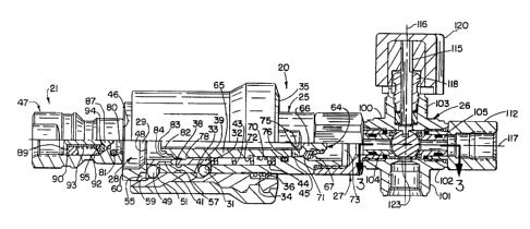
Fig. 1 is a plan view of a coupling system with the coupler and mating
nipple thereof disconnected.
Fig. 2 is a half elevational, half sectional view of the coupler and mating
nipple taken from the line 2-2 of Fig. 1.
Fig. 3 is a partial sectional view showing a venting position of a ball
valve employed in the coupler of Fig. 1, taken substantially along the line 3-
3
of Fig. 2.
Figs. 4 and 5 are views similar to Figs. 1 and 2, respectively, but
showing the nipple and coupler connected together and in a full vent mode.
Figs. 6 and 7 are views similar to Figs. 4 and 5, respectively, but
showing the connected coupler and nipple in a full open mode for transfer of
pressurized media therethrough.
Figs. 8 and 9 are views similar to Figs. 1 and 2, respectively, showing
the coupler in a miscocked condition.
SUBSTITUTE SHEET (RI~~E 26~
WO 94/13990 ~ ' ''~ ' - PCT/US93111G88
6
DETAILED DESCRIPTION
Referring now in detail to the drawings and initially to Figs. 1 and 2, a
preferred embodiment of the invention is illustrated by way of a coupling
system indicated generally at 18. The coupling system 18 comprises a
coupler 20, i.e. a female coupling, and a mating nipple 21, i.e., a male
coupling. As the illustrated coupler 20 was conceived and developed for use
in a CNG refueling system, it will be described chiefly in this context;
however, those skilled in the art will readily appreciate that the inventive
concepts embodied in the coupler 20 and the components thereof will be
useful in applications other than CNG refueling systems. In general, the
coupler 20 and mating nipple 21 are particularly suited for high pressure
applications requiring quick coupling and uncoupling of the mating couplings
at atmospheric pressure when one or both of the couplings are under
pressure.
The coupler 20 includes a coupler housing 24 formed by an elongated
tubular coupler body 25, a valve body 26 and an end connector 27 connected
between the coupler body and valve body. The coupler body 25 has an
axially extending through passage or bore 28. The forward end portion of the
passage 28 is configured to form a socket 29 for receiving the nipple 21.
The coupler body 25 has a locking sleeve 30 slidably mounted thereon
for telescoping axial movement. ~ When the coupler 20 is uncoupled from the
nipple 21 as shown in Figs. 1 and 2, the locking sleeve 30 is held in a cocked
uncoupled or release position by at least one and preferably a plurality of
radially outwardly displaced detents 31. In the illustrated embodiment there
are three circumferentially equally spaced apart detents in the form of balls
that are located in respective apertures 32 in the coupler body 25 for radial
movement.
The radially outwardly displaced detents 31 engage in an annular
cocking groove 33 formed in the inner diameter surface of the locking sleeve
30. The detents 31 axially interfere with the rearward side or stop surface of
the cocking groove 33 to prevent the locking sleeve 30 from being shifted
SUBSTITUTE SHEET (RULE 26)
WO 94/13990 ~ ~ PCT/US93/11688
' .. h .
forwardly (to the left in Figs. 1 and 2) by the biasing action of a coil
spring
34. The sleeve spring 34 is telescoped over the coupler body 25 and is
housed within a counterbore in the rear face 35 of the locking sleeve. The
sleeve spring 34 is trapped between the bottom of the counterbore in the
locking sleeve and a retaining ring 36 on the coupler body 25 for resiliently
urging the locking sleeve forwardly along the coupler body.
The locking sleeve retainer detents 31 are each engaged and held in
their radially outwardly displaced position by a cylindrical retaining surface
38
at the outer diameter of a cocking member 39. The cocking member 39 in the
illustrated embodiment is in the form of an internal ring mounted for
telescoping sliding movement within the socket 29. The cocking member or
ring 39 is positioned within the socket so that it will be engaged and shifted
axially rearwardly by the nipple 21 when the nipple is axially inserted into
the
socket 29. The retaining surface 38 extends along a portion of the axial
length of the cocking ring and forwardly to a radial relief formed by an
annular
uncocking groove 41 in the cocking ring. The cocking ring is biased forwardly
(to the left in Fig. 2) by a coil spring 43 interposed between the rear end of
the cocking ring and an internal shoulder 44 formed at the intersection of the
socket 29 with a relatively smaller diameter valve guide bore 45 forming an
intermediate portion of the passage 28 extending axially through the coupler
body 25.
When the nipple 21 is axially inserted into the socket 29, the front face
46 of the body 47 of the nipple 21 will engage the front face 48 of the
cocking ring 39 and push the cocking ring rearwardly. During an initial range
of movement of the cocking ring the retaining surface 38 thereof will hold the
locking sleeve retainer detents 31 radially outwardly displaced and engaged
in the cocking groove 33 of the locking sleeve 30 thereby holding the locking
sleeve in its cocked position as shown in Fig. 2. When the cocking ring has
been shifted sufficiently to bring the uncocking groove 41 into radial
alignment
with the detents 31, the detents 31 will then be free to move radially
inwardly
and out of the cocking groove 33 in the locking sleeve. This will allow the
SU~ST~TUTE SHEET (Rt~LE ~~)
WO 94/13990 ~ . j ~ .~ , PCT/US93/11688
;. , . :--.
8
locking sleeve 30 to move forwardly with the assistance of the locking sleeve
spring 34. The rearward sloped surface of the cocking groove 33 will cam the
detents radially inwardly into the uncocking groove 41 in the cocking ring and
out of the cocking groove, so that the locking sleeve may be moved forwardly
from its cocked uncoupled or release position in Figs. 1 and 2 to its uncocked
coupled or lock position in Figs. 4 and 5.
As the locking sleeve 30 moves forwardly from its cocked position to
its uncocked position shown in Figs. 4 and 5, it will cause at least one and
preferably a plurality of nipple locking detents 49 to be radially inwardly
displaced into an annular locking groove 50 of the nipple 21. In the
illustrated
embodiment there are eight circumferentially equally spaced apart detents 49
in the form of balls that are located in respective apertures 51 in the
coupler
body 25 for radial movement between radially outwardly and inwardly
displaced positions shown in Figs. 2 and 5, respectively.
When the nipple 21 has been inserted into the coupler socket 29 a
sufficient distance to effect release of the locking sleeve 30 in the above
described manner, the nipple's locking groove 50 will be aligned radially with
the nipple locking detents 49. This allows the nipple locking detents 49 to be
forced radially inwardly by a sloped camming shoulder 54 formed at the
bottom of a forwardly opening counterbore 55 in the locking sleeve 30. After
the nipple locking detents 49 have been radially inwardly displaced into the
nipple's locking groove 50, a ball retainer surface 57 at the inner diameter
of
the locking sleeve 30 moves over the nipple locking detents as the locking
sleeve moves into its uncocked coupling position shown in Figs. 4 and 5. The
ball retaining surface 57 holds the nipple locking balls in their radially
inwardly
displaced position to prevent their disengaging from the nipple's locking
groove 50, thereby to securely lock the nipple 21 to the coupler 20. .
The counterbore 55 at the forward end of the locking sleeve 30 is
stepped to form a stop surface 59 axially forwardly of the shoulder surface
54. The stop surface 59 engages a radially outwardly protruding stop flange
60 at the forward end of the coupler body 25 to limit forward movement of
SUBSTITUTE S:~=ET BRIDLE 26~
WO 94/13990 ~ PCT/US93111688
.. _. t,
the locking sleeve and thereby define the uncocked coupled position of the
locking sleeve.
The nipple 21 may be uncoupled from the coupler 20 by manually
shifting the locking sleeve 30 rearwardly to its cocked position. As the
locking sleeve moves out of its uncocked coupling position shown in Figs. 4
and 5, the detent retaining surface 57 at the inner diameter of the locking
sleeve will move out of engagement with the nipple locking detents 49
thereby freeing the balls for radially outward displacement into a radial
relief
formed by the inner region of the counterbore 55. At the same time, the
cocking groove 33 in the locking sleeve 30 will be aligned radially with the
locking sleeve retainer detents 31. The retainer detents 31 may then move
radially outwardly to release the cocking ring 39 which will be urged
forwardly
by the cocking ring spring 43. In turn, the nozzle 21 will be urged out of the
socket 29 by this spring action while the nipple locking detents 49 are
cammed out of the nipple locking groove 50. As the cocking ring is shifted
forwardly from its position shown in Fig. 5, the retaining surface 38 will
once
again engage and hold the locking sleeve retainer detents 31 radially
outwardly displaced and engaged in the cocking groove 33 of the locking
sleeve 30, thereby holding the locking sleeve in its cocked position as shown
in Fig. 2.
Further in accordance with the invention, the coupler 20 includes an
internal stop valve 64. The stop valve has a tubular stem portion 65 and a
reduced diameter head portion 66 which closes the rearward end of the
tubular stem 65. The tubular stem is supported for axial movement in the
guide bore 45 in the coupler body.
The head portion 66 has secured thereto a radially enlarged annular seal
67 by a nut 68 threaded onto the head portion. The seal 67 is normally held
closed by a valve spring 70 against an annular valve seat 71 formed by a
sloped shoulder at the intersection of the guide bore 45 and a rear end
portion
73 of the passage 28 in the coupler body 25. The valve spring 71 is
interposed between the shoulder 44 and a shoulder 72 on the valve stem 65
SU~TITUTE SNEET (Rt~IE 26
WO 94/13990 " ~- ' ' ~~': :, PCT/US93/11688
for resiliently urging the valve body in a forward direction to maintain the
valve seal 67 in sealing engagement with the annular valve seat 70 thereby
blocking flow of any pressurized media through the coupler body 25.
When the nipple 21 is inserted into the socket 29 of the coupler 20, the
5 nipple contacts the forward end of the stop valve 64 and pushes the stop
valve stem rearwardly to move the valve seal 67 off of the valve seat 71.
Also, radial openings 75 in the wall of the stem 65 just forwardly of the
valve
seal 67 will be shifted to the rear of the valve seat 71 to provide for
relatively
unrestricted fluid flow through the coupler body 25. That is, the radial
10 openings 75 establish a relatively large area flow path for fluid flowing
from
the rear end portion 73 of the coupler passage 28 to the interior of the valve
stem 65 for passage into the nipple 21. An annular seal 76 is provided to seal
between the valve stem and the coupler body to prevent leakage of fluid from
the just described flow path through the coupler body. The valve stem 65 has
an annular external shoulder for engaging an annular internal shoulder on the
cocking ring 39 as seen at 78 in Fig. 2 to provide a forward stop for the
cocking ring.
The forward end of the valve stem 65 is configured for mating
engagement in a socket 80 formed in the forward end of the body 47 of the
nipple 21. The socket 80 has retained therein an annular interface seal 81 for
sealing against leakage between the nipple body and the valve stem 65. As
shown in Fig. 2, the forward end of the valve stem is stepped to form a short
axially extending tubular portion 82 which telescopes into the annular
interface seal 81 as seen in Fig. 4 and which is surrounded by an annular
shoulder 83 that also engages the annular seal but at the forward side surface
thereof. The stem also has a further radially outward annular shoulder 84
which forms an abutment that is engaged by the front face 46 of the nipple ,
21 when inserted into the socket 29 in the coupler body 25.
The nipple 21 also includes an internal check valve 87. The check
valve 87 has a valve stem guided for axial movement in a spider retainer 89
located within the interior passage of the nipple 21 by a retainer ring 90.
The
SUBSTITUTE SHEET ~RI~~E 2~~
WO 94/13990 ~ PCT/US93/11688
11
valve stem terminates at a radially enlarged head that is normally urged
against a valve seat 92 by a coil spring 93. The spring 93 also acts upon an
annular valve seal 94 through a follower 95 to hold the valve seal to the back
side of the valve head. The valve seal 94 extends radially beyond the valve
head to also engage against the valve seat 92 to prevent flow through the
nipple 21. Accordingly, the nipple 21 may be attached to the end of a
pressurized conduit, the check valve operating to prevent fluid from escaping
thro~~gh the nipple. By way of specific example, the nipple 21 may be coupled
to tt~e fill line of a vehicle through which compressed natural gas may be
supplied via the coupler 20 to fill a storage tank contained in the vehicle.
When the nipple 21 is coupled to the coupler 20, the check valve 87
will be held closed by the check valve spring 93 and also by fluid pressure in
the conduit to which the nipple 21 is attached. However, when high pressure
media is flowed through the coupler 20 to the nozzle, the nozzle check valve
will open once the pressure in the coupler exceeds the pressure behind the
nipple's check valve, thereby to allow flow to occur. The flow of pressurized
media through the coupler is controlled by a valve element in the form of a
ball valve 98 mounted in the valve body 26.
The valve body 26 is joined with the coupler body 25 by the end
connector 24. The end connector 24 is internally threaded at one end for
threaded attachment to the externally threaded rear end portion of the coupler
body 25 and it is externally threaded at' its opposite end for threaded
receipt
in an internally threaded passage in one leg 100 of 'the valve body. The valve
body has the shape of a cross and, accordingly, has three other legs 101-103
in addition to the leg 100 to which the coupler body is attached. The four
legs 100-103 are disposed in a common plane at right angles with respect to
one another.
The legs 100-103 have passages extending therethrough and
intersecting at the center of the valve body where the ball valve 98 is
located.
The ball valve is retained between a pair of ball valve seal assemblies 104
and
105 on opposite sides thereof. As best shown in Fig. 3 each ball valve seal
SUBSTITUTE SHEET (RULE 26)
WO 94/13990 ' PCTIUS93/11688
12
104, 105 includes a retainer ring 106, 107 having at its inner end an annular
seal 108, 109 that engages the ball valve to prevent leakage between the ball
valve and the retainer ring. The seal assemblies 104 and 105 are preferably
spring loaded against the sides of the ball valve by wave springs 1 10 and
11 1. In the illustrated embodiment, the ball,valve seal assembly 104 in the
valve body leg 100 is retained in the passage thereof by the externally
threaded end of the end connector 24. Similarly, the ball valve seal assembly
105 in the opposite leg 102 is retained by the externally threaded portion of
another end connector 1 12 which is threaded into the passage in the leg 102.
At the upper end of the ball valve 98 as illustrated in Fig. 1, there is
provided a slot for receiving a key at the end of a handle stem 1 15 whereby
the ball valve may be rotated through 90 ° about an axis 1 16 extending
perpendicular to the common axis 1 17 of the ball valve seat assemblies. The
rotation axis 116 also is aligned with the lower and upper legs 101 and 103
of the valve body 26. The stem 115 is supported for rotation about its axis
in a packing nut 1 18 threaded into the upper leg 103 of the valve body. The
stem projects upwardly beyond the packing nut and has keyed thereto a
handle 120. Suitable packing and a retainer therefore may be interposed
between the packing nut and the bottom of the passage in the upper leg 103
to seal against the escape of pressurized fluid through the passage in the
upper leg, as is conventional. The handle 120 may be rotated through 90
°
to similarly rotate the ball valve 98 between open and closed positions.
The lower leg 101 of the valve body 26 has an interior passage which
opens at a port 123 to the bottom of the ball valve 98 between the ball valve
seals 108 and 109. The port 123 is herein referred to as the inlet port as it
is normally intended to be connected to a supply of pressurized media to be
dispensed through the coupling 20 to the nipple 21. The passage in the lower .
leg 101 may be internally threaded or otherwise suitable configured for
receipt
of an end connector or other fitting as desired to effect connection to a
supply
of pressurized fluid such as a storage tank for compressed natural gas.
SUBSTITUTE SHEET (RI~~.E ~~~
WO 94/13990 ~ ~ PCT/US93/11688
13
The ball valve seal assemblies 104 and 105 have through passages 125
and 126 which open to opposite sides of the ball valve at ports 127 and 128,
respectively. The port 127 is herein referred to as the outlet port as
pressurized fluid would normally be dispensed through this port to the nipple
21 via the coupler body 25. The other port 128 is herein referred to as the
vent port as its function in the illustrated preferred embodiment is to vent
pressurized fluid that is trapped in the coupler body 25 when the ball valve
98
is closed. The outlet and vent ports 127 and 128 are surrounded by the ball
valve seals 108 and 109, respectively, and are thereby separated from the
region between the ball seats that is in communication with the inlet port
123.
The vent port 128 may communicate with the atmosphere directly or via a
muffler, filter, etc., as may be desired. Alternatively, the vent port may be
coupled to a reclamation or recycling system for reclaiming or recycling
pressurized media vented through the vent port, as is particularly desirable
in
a CNG refueling system. Preferably, the compressed natural gas is reclaimed
to prevent product loss and further to protect against any adverse
environmental impact that venting of the compressed natural gas to the
atmosphere may have.
The ball valve 98 has a valve passage 131 for permitting flow from the
inlet port 123 to the outlet port 127 when the ball valve is in its open
position. The valve passage 131 has an inlet at the bottom of the ball valve
which is concentric with the inlet port 123 and consequently the rotational
axis 1 16 of the ball valve. At its other or outlet end, the valve passage
opens
to a side of the ball valve for rotation into and out of communication with
the
outlet port 127 when the handle 120 is rotated 90 ° between open and
closed
positions.
As seen in Fig. 1, the handle 120 has an ear portion 132 that has an
arcuate abutment surface 133 concentric with the rotation axis 1 16 of the
ball valve 98. When the locking sleeve 30 is in its cocked position as shown
in Fig. 1, the front face 35 of the locking sleeve will interfere with the
abutment surface 133 to prevent rotation of the handle 120 beyond its
SU~STI'fUTE SHEET (Rt~LE ~6~
WO 94/13990 PCT/US93/11688
14
position illustrated in Fig. 1. This will prevent the ball valve 98 from being
rotated beyond its position shown in Fig. 3 where the ball valve has not been
rotated sufficiently to establish communication between the inlet port 123 and
the outlet port 127. Accordingly, the ball valve cannot be rotated into its
open position so long as the locking sleeve 30 remains in its cocked position
shown in Fig. 1.
The ball valve 98 also has a vent passage 134 extending generally
between diametrically opposed sides of the ball valve generally in a plane
perpendicular to the rotation axis 116 of the ball valve. The vent passage 134
is operable to effect fluid communication between the outlet port 127 and the
vent port 128 when and only when the ball valve is in its closed position.
More particularly, the opposite ends of the vent passage are positioned so as
to communicate respectively with the outlet port and vent port only when the
ball valve is in its closed position. When the ball valve is in its open
position,
the vent passage 134 is rotated out of fluid communication with the vent port
128.
The operation of the coupler 20 will now be described with initial
reference to Figs. 1-3. The coupler is there shown ready to be coupled with
the nipple 21 as by pushing the coupler 20 onto the nipple. Accordingly, the
locking sleeve 30 is in its cocked release position which, as above mentioned,
limits rotation of the handle 120 to a point short of the ball valve being
opened, thereby protecting against the ball valve being opened when the
coupler 20 is not connected to the nipple 21. Also, the coupler will be in a
vent mode with the vent passage 134 in the ball valve providing
communication between the outlet port 127 and the vent port 128 at any
position of the bail valve between its position shown in Figs. 1-3 and its
full
closed position shown in Figs. 4 and 5. That is, the coupler will remain in
its
vent mode between its full closed position and its position shown in Figs. 1-3
where the handle has been rotated to its point of interference with the
locking -
sleeve.
SUBSTITUTE SHEET (RI~I.E 26~
WO 94/13990 PCT/1JS93I11688
With the coupler 20 in its vent mode, the coupler may be connected
with the mating nipple 21. To make a connection, the nipple is inserted into
the coupler's socket 29, moving the cocking ring 39 rearwardly to the point
that allows the locking sleeve retainer detents 31 to move into the release
5 groove 41 in the cocking ring. This allows the locking sleeve 30 to move
forward with the assistance of the locking sleeve's spring 34. This action
forces the nipple locking detents 49 radially inwardly into the nipple's
locking
groove 50 thereby locking the nipple to the coupler.
Also during insertion of the nipple 21 into the socket 29, the stop valve
10 64 in the coupler 20 will be engaged by the nipple and shifted rearwardly
thereby moving the annular valve 67 off of the valve seat 71. The forward
end of the stem 65 of the stop valve 64 will also be sealingly engaged in the
nipple socket 80.
Coupling of the coupler 20 with the nipple 21 will be accomplished
15 without actuating the check valve 87 in the nipple. The check valve 87 may
remain pressurized and held in its position shown in Fig. 2 to prevent the
escape of any pressurized media from behind the check valve.
In Figs. 4 and 5, the coupler 20 and nipple 21 are shown coupled
together and ready for transfer of pressurized media from the coupler to the
nipple. Figs. 4 and 5 also show the handle 120 in its full closed and vent
position. The handle extends perpendicular to the longitudinal axis of the
coupler 120 to provide a visual indication of the closed position of the
coupler
ball valve 98. Also, the ear of the handle may be marked with "VENT" and
"FILL" and a direction indicating arrow 140 to facilitate operation of the
coupler. Counterclockwise rotation of the handle beyond its full closed
position illustrated in Fig. 4 is precluded by a stop indicated at 141 in Fig.
5
whicv engages an abutment surface 142. A similar stop and abutment
surface are provided to prevent clockwise rotation of the handle beyond its
full
open position shown in Fig. 6. Accordingly, rotation of the handle is limited
to rotation through 90 ° between full closed and full open positions
respectively shown in Figs. 4 and 6.
S~B'~TITUTE SHEET (~(~LE ~,~~
WO 94/13990 PCT/US93/11688
16
As indicated, the handle 120 can be turned clockwise from its full
closed position to its full open position shown in Figs. 6 and 7. In this
position the handle extends parallel to the longitudinal axis of the coupler
body
25. As the handle is rotated from its full closed position to its full open
position, the ball valve 98 will be turned to establish communication between
the inlet port 123 and the outlet port 127 via the generally L-shaped passage
131 in the ball valve 98. Before the outlet end of the valve passage 131
moves into communication with the outlet port 127, the vent end of the vent
passage 134 will move out of communication with the vent port 128.
Upon opening of the valve ball, pressurized media may flow from the
inlet port 123 to the outlet port 127 and then through the interior passage 28
of the coupler body 25, as the stop valve 64 will then be held off the valve
seat 71 as above indicated. Once the pressure in the flow passage through
the coupler 25 exceeds the pressure behind the nipple's check valve 87, the
nipple's check valve will open and flow will occur from the coupler to the
nipple. In the on or flow position, the handle 120 will function as an
obstruction preventing rearward movement of the locking sleeve 30. This will
prevent uncoupling of the nipple from the coupler. During media transfer, the
nipple's interface seal 81 contacts the stem 65 of the stop valve 64 to
prevent media from escaping into the atmosphere.
Should the pressure acting on opposite sides of the nipple's check valve
87 become balanced, the check valve will close and prevent any further flow.
This will occur when the handle 120 is rotated to shut off the supply of
pressurized media and vent the coupler. As the handle is rotated from its full
open position to its full closed position, the outlet end of the passage 131
in
the ball valve 98 will move out of communication with the outlet port 127 and
then further rotation of the ball valve will rotate opposite ends of the vent
passage 134 into fluid communication with the outlet and vent ports 127 and
126, thereby venting the coupler 20. Also, the handle will have been rotated
out of its position blocking rearward movement of the locking sleeve 30
thereby allowing the coupler to be disconnected from the nipple.
s.uBSTi~uT~ ~~~~r ~~~~.~ ~~~
WO 94/13990 ~ PCT/LJS93/11688
17
Referring now to Figs. 8 and 9, a further feature of the coupler 21 is
illustrated. Should the coupler 21 somehow become miscocked (false
connected) to allow the locking sleeve 30 to move to its coupled position
without the coupler being connected to a matirig nipple, the stop valve spring
72 will function to hold the stop valve closed against the valve seat 71. Even
if the ball valve 98 is turned on by rotation of the handle 120 to its
position
illustrated in Figs. 8 and 9, the stop valve will prevent the flow of
pressurized
media through the coupler.
Summarizing, the interlocking features of the coupler require the user
to couple and uncouple the coupler to a mating nipple with the coupler in its
vent mode. The coupler will not allow pressurized media to flow therethrough
unless coupled to a mating nipple. Once the coupler is connected to the
mating nipple and the supply is turned on, the user cannot uncouple the nipple
from the coupler without first placing the coupler in its vent mode. Even in
the unlikely event that the coupler is miscocked and the valve is turned on,
internal valuing within the coupler prevents any flow of pressurized media.
Accordingly, the aforedescribed coupler minimizes the potential for misuse.
Although the invention has been shown and described with respect to
a preferred embodiment, equivalent alterations and modifications will of
course occur to others skilled in the art upon the reading and understanding
of this specification. The present invention includes all such equivalent
alterations and modifications, and is limited only by the scope of the
following
claims.
SUBSTITUTE ~I~L~T RULE 2~~