Note: Descriptions are shown in the official language in which they were submitted.
215199~
The present invention relates generally to portable
electrical humidifiers, and more specifically to those known as
impeller or "cool mist" type humidifiers, which employ a fan, a
spinning suction tube, and a diffuser screen. Mist is created
mechanically through collision of water dispersed by the spinning
tube against the diffuser screen and is exhausted after mixing with
air by the fan.
Impeller humidifiers have been known for many years and it
is common to employ therewith an overfill protection hole which
prevents water poured into a reservoir from rising above a pre-
determined maximum. In that way the undesirable wetting of the
motor or other electrical components within the humidification unit
is avoided. Normally the protective hole is located in a wall of
the humidifier tank and vertically positioned at that maximum water
level. However, as a result of turbulence created by the spinning
suction tube, unintended escape of moisture may occur through the
overfill protection hole in the same manner as intended moisture
is released at the exhaust opening. Such inadvertently escaping
moisture may contact and damage objects such as furniture or wall
coverings located behind the humidifier.
one solution to the above described drawback is to attach
a tube to the overfill protection hole which depends down from the
hole to below the minimum water level of the reservoir. Pressurized
21~1992
air and mist within the reservoir tank are prevented from un-
intentional escape at the overfill protection hole by the water
within the tank surrounding the tube which water forms a seal.
If the lower end of the tube is below the lowest level achieved
during the humidifier's operation, air and mist cannot escape even
as the water supply in the reservoir is depleted. However, prior
art overfill protection tubes however have had the disadvantages
of being an additional component to the humidifier. In addition
to the increased costs associated with the manufacture and assembly
involved, the protective tubes can be unintentionally removed and
lost.
It is the object of the present invention to overcome
these drawbacks and provide a humidifier with an improved overfill
protection tube.
These and other objects and features of the invention
will become more apparent upon a perusal of the following
description taken in conjunction with the accompanying drawings
wherein:
Fig. 1 is a perspective view of a humidifier in accordance
with the present invention;
Fig. 2 is a side view of the humidifier of Fig. l;
Fig. 3 is a front view of the humidifier of Fig. l;
21~19~
Fig. 4 is a back view of the humidifier of Fig. l;
Fig. 5 is a top view of the humidifier of Fig. l;
Fig. 6 is a bottom view of the humidifier of Fig. l; and
Fig. 7 is a sectional view taken on plane A-A of Fig. 5.
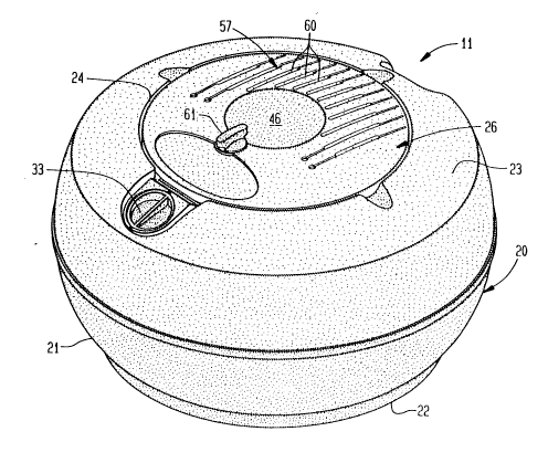
A portable humidifier 11 includes a housing 20 that
defines a reservoir 12 shown in Fig. 7. The housing 20 is a blow-
molded polypropylene tank 21 having a continuous wall thickness
of approximately 0.060". As shown, the tank 21 is basically
spherical in ~hape, truncated and closed at a bottom wall 22 to
provide a stable base and truncated and open at a top portion 23.
An opening 24 in the top portion 23 receives a humidification unit
26 that is supported by a continuous annular shelf 27. A smaller
opening 30, concentric with the larger opening 24 provides access
into the reservoir 12 for a diffuser screen 31 and suction tube 32
of the humidification unit 26. The opening 30 also functions as a
water filling hole for the tank 21. An opening 33 in the upper
surface of the housing 20 serves as an exhaust opening through
which mist and air are exhausted from the humidifier 11.
The tank 21 also includes an integrally molded overfill
protection tube 34 which prevents the water level 35 within the
reservoir 12 from rising above a predetermined maximum level 36
when being filled. The top surface 37 of the tube 34 is vertically
positioned at the maximum operating level 36 and the bottom surface
21~1g~7
40 of the tube is vertically positioned below a minimum operating
level 41 closely adjacent to the tank bottom 22. As the tank
is filled, excessive water will result in spillage out of the
top 37 of the overfill protection tube and out of the reservoir 12.
This prevented a rise in water level to a height which would result
in the wetting of a motor 42 or other electrical parts within the
humidification unit 26 when it is positioned on the tank 21. As
the water level drops during use of the humidifier 11, air and
mist within the tank 21 are prevented from inadvertent escape
through the overfill protection tube 34 by the cylindrical wall 43
of the tube which projects down from the tube's top surface 37.
Water within the reservoir 12 and surrounding the cylindrical
wall 43 of the tube 34 provides a seal to maintain the air and
mist above the water level 35. Since the lower surface of the
tube 34 is positioned lower than the minimum water level 41,
achieved when the water falls below the lower tip 44 of the
suction tube 32, the overfill protection tube 34 is always sealed
within the water to prevent air and mist leakage when the
humidifier is operating.
The humidification unit 26 includes a partially spherical
injection molded plastic cover 46 which also serves as a mounting
plate for the motor 42 and a switch 47. Integrally molded and
--5--
2151992
depending from the cover 46 are an outer cylindrical ring 50 and
an inner cylindrical housing 51. A lower end of the inner
cylindrical housing 51 forms a cylindrical diffuser screen 31
comprised of a continuous series of slots 53 approximately 0.060"
wide adjacent solid separators 54 approximately 0.060" wide. The
motor 42 is mounted by screws (not shown) on an underside 55 of
the cover 46 and has a shaft 56 directed downwardly therefrom.
Sharing a common axis are the outer cylindrical ring 50, the inner
cylindrical housing 51, and the motor shaft 56.
The cover 46 defines an air intake vent 57 consisting
of a series of elongated slots 60. Mounted to the cover 46 by
screws (not shown) is the control switch 47 whose shaft (not
shown) extends upwardly through a hole (not shown) in the cover
46 and is attached to a switch knob 61. The cylindrical outer
ring 50 is slightly smaller in diameter than the large hole 29
at the top of the tank 21 to allow for proper radial positioning
of the humidification unit 26. When the humidification unit 26
is lowered onto the reservoir 12, a bottom edge 62 of the outer
ring 50 contacts an upper surface 63 of the annular shelf 27 to
properly position the humidification unit 26 vertically.
Attached to the motor shaft 56 by pressure-fit is an
injection molded plastic fan blade 64 consisting of a flat
21519g2
circular disk 65 having a series of radially positioned ridges 66
extending upwardly therefrom. An outer edge 70 of the blade 64
is vertically aligned with and radially spaced from the diffuser
screen 31 by approximately 0.125" to 0.25". The combination of
the disk 65, the inner cylindrical housing 51, and the cover 46
form an enclosure for the motor 42, switch 47 and electrical wiring
78 therefor. When the blade 64 is rotated by the motor 42, the
upwardly extending ridges 66 expel air in a tangential direction
through centrifugal force toward the diffuser screen 31. As air
is expelled from the blade 64, it is thereby also drawn through
the intake openings 57 of the cover 46. The only escape for air
drawn into the humidifier 11 is out the exhaust opening 33.
Engaged to the bottom side of the flat disk 65 of the
fan blade 64 is the injection molded plastic suction tube 32.
As shown in Fig. 7, the tube 32 consists of an inverted hollow
cone 73 defining a conically shaped cavity 81 and having an open
top end 74, a first conical portion 75 of approximately sixty
inclusive angular degrees, a second conical portion 76 of
approximately five inclusive angular degrees, and a truncated
apex 77 at its lower tip. The apex 77 of the cone 73 is located
below the operating water level in the reservoir 12 and defines
a suction intake hole 80 axially positioned at the lowest tip
of the tube 32 to allow water to enter the hollow cavity 81.
2151992
Energization of the motor 42 results in spinning of the suction
tube 32 which draws water in an upward and outward direction by
centrifugal force until it reaches a pair of water outlet holes 82
axially spaced one hundred and eighty angular degrees and closely
adjacent to the top of the tube 32.
Water that rises within the tube 32 but does not
immediately escape through the outlet holes 82 will collect against
the fan blade 64 and will be redirected towards and eventually
through the outlet holes 82. As the water is dispersed through
the outlet holes 82 it sprays against the diffuser screen 31 where
it is broken up into a mist. Larger droplets of the mist and
water which collects on any other surfaces within the humidifier 11
fall back into the reservoir 12 and will again be drawn into the
suction tube 32. Finer droplets of the mist remain airborne and
are easily carried by the airflow of the fan through the exhaust
opening 33 and out into the environment.
Obviously, many modifications and variations of the present
invention are possible in light of the above teachings. It is to
be understood, therefore, that the invention can be practiced
otherwise than as specifically described.